Table of Contents
Advertisement
Instruction Manual XENAX® Xvi
75V8S
Translation of "Anleitung XENAX® Xvi 75V8S"
Edition 19. November 2020
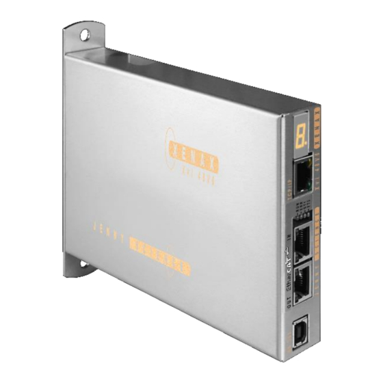
Compact Ethernet Servo Controller
Parameterization over Web browser
Th e in t eg rat ed w eb s erv er al lo ws a s etu p
an d p ar a me te ri zat ion o v er w eb b ro ws er .
Af te r an au to m ati c s el f - ch e ck, th e
con n ec t ed L IN A X® li n e ar mo tor ax is , th e
E LA X® e le ct ri c s l id e or t h e RO T AX ® r ota ry
axis can in s ta n tly b e s e t in mot ion b y c li ck
on th e Qu ic k Star t B u tto n .
Th is XE N A X® Xv i 7 5V 8 S i s s ett in g n ew
s tan d ard s in te r ms o f i n tu it iv e h an d lin g.
Advertisement
Table of Contents

Related Manuals for Jenny Science XENAX Xvi 75V8S

Summary of Contents for Jenny Science XENAX Xvi 75V8S
- Page 1 Instruction Manual XENAX® Xvi 75V8S Translation of “Anleitung XENAX® Xvi 75V8S” Edition 19. November 2020 Compact Ethernet Servo Controller Parameterization over Web browser Th e in t eg rat ed w eb s erv er al lo ws a s etu p an d p ar a me te ri zat ion o v er w eb b ro ws er .
- Page 2 Gener al Th e XE NA X ® Xv i 7 5 V8 S E th e rn e t s erv o con t rol l er con t ro ls al l s er ies o f th e L IN AX ® lin ear moto r a xes , th e E LA X®...
-
Page 3: Table Of Contents
5.2.5 Definition of Rotating Direction for Servo Motors 5.2.6 OPTIO CAN, Pulse/Dir, Second Encoder Channel 5.2.7 PLC I/O 5.3 Internal I/O Circuit 5.4 Output Configuration 6 Configuration Motor Type Jenny Science / Motor customer specific 7 USB/COM Socket 7.1 USB Operation... - Page 4 7.2 RS232 Operation 8 ETHERNET TCP/IP Interface 8.1 Test IP Connection with >IPCONFIG 8.2 Test Connection with >PING 8.3 Close Port 10001 9 ASCII Protocol 9.1 ASCII Protocol TCP/IP 9.2 Asynchronous Messages (Events) 10 WebMotion® 10.1 Start WebMotion® 10.1.1 Error „Upload XENAX Settings®“ 10.2 Quick Start (only with LINAX®...
- Page 5 10.11 Sector I_Force 10.12 Program 10.12.1 Program commands 10.13 I/O Functions 10.13.1 Selection of Input Functions 10.13.2 Selection Output Functions 10.13.3 Operation with Additional Holding Brake 10.14 Profile (Velocity) 10.15 Captured Pos 10.16 State Controller 10.16.1 F Setting 10.17 Motor 10.17.1 Motors LINAX®...
- Page 6 13.2.3 Sector Offset for Touching Position 13.3 Application Example 13.3.1 Programming Force Process in XENAX® 13.3.2 Force Process with ASCII Commands 14 Operating Status on 7-Segment Display 15 Error Handling 15.1 Error Codes 15.2 Notes for Error 50 15.3 Notes for Error 89 15.4 Notes for Error 91 15.5 Arbitrary Display on 7-Segment 15.5.1 Defective adapter for logic supply...
-
Page 7: Characteristics Xenax® Xvi 75V8S
1 Characteristics XENAX® Xvi 75V8S 1.1 Electronics / Firmware Description Data Interfaces Ethernet, TCP/IP, http web server Puls/direction, Master Encoder, I/O C Master/Slave, Start-up Key USB (standard) or RS232 (optional), CAN for Signateq® measuring amplifier Bus, multi-axis operation EtherCAT (CoE), DS402 Ethernet POWERLINK, DS402 CANopen, DS 402 PROFINET (PROFIdrive) -
Page 8: Dimensions
Motor temperature observation with LINAX®, ELAX® Shutdown at 80°C and ROTAX®, sensor in coils PLC Input 8 Inputs, 24V PLC Input BCD 4 Inputs, 24V, binary coded for program selection PLC Output 8 Outputs, 24V, Source 100mA, Sink 400mA, Source/Sink Options EtherCAT (CoE) DS402, Beckhoff®, OMRON®, TRIO®... -
Page 9: 75V8 Versus Xvi 75V8S
1.4 Xvi 75V8 versus Xvi 75V8S The XENAX® Xvi 75V8S is the evolution of the current model XENAX® Xvi 75V8. The new model supports all the previous functionalities of the Xvi 75V8, has the same dimensions and can therefore be replaced 1:1. For new developments we recommend to use the Xvi 78V8S. -
Page 10: Controllable Motor Types
2 Controllable Motor Types 2.1 Linear Motor Axes and Electric Slides LINAX® Linear Motors 3 phase synchronous linear motor with encoder RS422 A/A*, B/B* und Z/Z* and distance-coded reference marks. Special feature: Linear motor identification and temperature monitoring over I2C bus. ELAX®... -
Page 11: Customary Servo Motors
La fer t , R A x x, RT x x AC-Servo motors with encoder A/A*, B/B* and Z/Z* and hall sensors e.g. AEG B28 D4 0,4Nm, 6000 U/min. Optionally available with brakes for vertical applications. 2.3 Customary Servo Motors Fau lh a b er ®... -
Page 12: Hardware And Installation
3 Hardware and Installation 3.1 Environmental Conditions Storage and transport No outdoor storage. Warehouses have to be well ventilated and dry. Temperature from -25°C up to +55°C Temperature while operating 5°C -50°C environment, (above 40°C, nominal current reduced to 6A) Humidity while operating 10-90% non-condensing Air conditioning... -
Page 13: Functional Safety - Tüv Certified
SIL 2, PL d, Cat. 3 a separate article number. XENAX® Servo controllers can only be upgraded to SMU at Jenny Science. Upgrade is only possible with hardware V 4.0 or higher SMU modules will only be supplied when mounted into a XENAX®... -
Page 14: Basic Conditions
4.3 Basic Conditions Motor Types Functional Safety with SMU can be used for all LINAX®, ELAX® and ROTAX® motor families, as well as rotary brushless motors with different A/B/Z encoder signals. Rotary brush type DC motors are not subject to the functional safety. Note1: For vertical mounted linear axis, weight compensation must be used for safety functions SS2 and SLS. -
Page 15: Technical Data Safety
4.4 Technical Data Safety Reaction time of the security inputs (until < 2ms activation of a safety function) Probability of a dangerous failure per hour (PFH) PFH = 51.7 * 10 Activation of a safety function Switching on two channel to 0V One-channel switched safety inputs lead to turn off of the power stage and requires a restart of the XENAX®... -
Page 16: Safety Functions
Deceleration ramps for SS1 Profile Position Mode and Cyclic Synchronized Trough parameter ED (Emergency Deceleration) Position Mode (RT-Ethernet) Deceleration ramps for SS2 Profile Position Mode With Parameter ED (Emergency Deceleration) Cyclic Synchronized Position Mode (RT-Ethernet Indicated by superior master controller Deceleration ramps for SLS Profile Position Mode After speed infringements through parameter ED... -
Page 17: Ss2, Safe Stop
4.5.3 SS2, Safe Stop 2 Stop while remaining in stop position, axis remains under power, power stage active. Then observation Safe Operating Stopp Safe Torque Off of stop-position, status SOS (Safe Operating Stop). If exceeding the position limit, STO will be triggered. Power stage Timeout Observation of standstill... -
Page 18: Functional Safety Parameterization In Webmotion
4.6 Functional Safety Parameterization in WebMotion® 4.6.1 Display Active Safety Parameters The defined Safety Functions and parameters are shown in WebMotion® in the menu application/io. This safety information can only be read, not modified. The parameters of the Safety Functions can be made visible by pressing „Safety Param“. - Page 19 Actual Current safety parameters of XENAX® servo controller with SMU. This is where new safety parameters can be selected from the drop down menu. They are activated in XENAX® servo controller by pressing „save“. save XENAX®: The modified safety parameters are being sent to XENAX®...
-
Page 20: Electrical Connections
5 Electrical Connections Note: To disconnect or connect the electrical components at the electrical connectors, the power supply must be disconnected. XENAX® Xvi 75V8S 5.1 Plug Arrangement Description Plug Type RS232 USB-B socket Real time Ethernet (optional) 2 x RJ45 socket with status LED CANopen (optional) 9 Pol socket D-Sub Ethernet TCP/IP... -
Page 21: Motor Plug 3 Phase
5.2.2 Motor Plug 3 Phase Wago 3 Pole Plug LINAX® / ELAX® Servo motor DC Motor 3 Phase 3 Phase U (white) DC + V (brown) DC - W (green) 5.2.3 Logic and Power Supply Wago 4 Pole Plug 0, GND Adapter logic 24V DC 0, GND... -
Page 22: Encoder And Hall Signals
5.2.4 Encoder and Hall Signals 15 pole D-Sub socket Signal Description Together, for encoder and hall 0V supply, only 1 pin 5V Encoder 150 mA for encoder supply Encoder A Pull up 2,7kΩ to 5V, differential input 26LS32 Encoder A* Middle level: pull up 2,7kΩ... -
Page 23: Optio Can, Pulse/Dir, Second Encoder Channel
5.2.6 OPTIO CAN, Pulse/Dir, Second Encoder Channel A CAN interface for communication with the Signateq® measuring amplifier is implemented as standard. It is possible to have a Pulse/Dir or a second encoder channel instead. CAN (standard) for communication with the Signateq® measuring ampl. Signal RJ45 OPTIO... -
Page 24: Plc I/O
5.2.7 PLC I/O Output Signal D-Sub PLC Cable PLC I/O Source PNP: 24V/100mA, Sink NPN: open collect. 24V/400mA Pin 1 white Output 1 (0/24V) Source PNP: 24V/100mA, Sink NPN: open collect. 24V/400mA Pin 2 brown Output 2 (0/24V) Source PNP: 24V/100mA, Sink NPN: open collect. 24V/400mA Pin 3 green Output 3 (0/24V) -
Page 25: Internal I/O Circuit
5.3 Internal I/O Circuit INPUT 1-12 HIGH or LOW ACTIVITY programmable OUTPUT 1-8 TYPE SOURCE TYPE ACTIVITY Output Output Bit-value Bit-value SOURCE HIGH 24V* open* open All Output SOURCE SOT 21845 SOA 255 / 0 TYPE SINK TYPE ACTIVITY Output Output Bit-value Bit-value... -
Page 26: Output Configuration
5.4 Output Configuration TYPE SOT (Set Output Type) parameter 16 Bit 2 Bit-value per output Output SOT Bit Bit- value Decimal 21845 *Default setting all output on SOURCE >SOT 21845 ACTIVITY SOA (Set Output Activity) parameter 8 Bit 1 Bit-value per output Output SOA Bit Bit-value... -
Page 27: Configuration Motor Type Jenny Science / Motor Customer Specific
6 Configuration Motor Type Jenny Science / Motor customer specific The XENAX® Servo Controller differentiates between Jenny Science Motors LINAX® Lx, ELAX® Ex or ROTAX® Rx, and motors from other manufacturers. The XENAX® Servocontroller recognises if the connected motor is a Jenny Science motor (LINAX® Lx, ELAX®... -
Page 28: Usb/Com Socket
7 USB/COM Socket 7.1 USB Operation A serial communication can be established over the USB/COM socket. By default, the serial communication is implemented with USB. This means that a computer can be directly connected with a XENAX® over a USB cable. The XENAX® will register itself as “serial USB device”... - Page 29 8 ETHERNET TCP/IP Interface The TCP/IP interface has two essential functions. Firstly, HTML5-WebMotion can be accessed over the Ethernet TCP/IP interface. Secondly, the Ethernet TCP/IP interface is used to control the axis with all available ASCII commands. The port 10001 I used for ASCII commands.
- Page 30 8.1 Test IP Connection with >IPCONFIG IPCONFIG command in DOS window Test TCP/IP address range. IP address has to be in range of 192.168.2.xxx If necessary adjust IP address in computer „network environment“ to e.g. IP 192.168.2.200. xxx = 001 – 255 ≠...
- Page 31 9 ASCII Protocol Over Ethernet TCP/IP in the menu move axis / by command line in WebMotion® or via the serial interface e.g. with hyper terminal. The simple ASCII protocol works with the echo principle. The sent characters come back as an echo and can be checked immediately.
- Page 32 9.1 ASCII Protocol TCP/IP In TCP/IP the cohesive ASCII sequences can be splitted into different telegram packages. This is why a separate receive buffer has to be considered. Please find detailed information in: „ Xvi75_TCP/IP_Socket_ Telegram_Events/Wireshark.pdf” on http://www.jennyscience.de/en/download/. 9.2 Asynchronous Messages (Events) To reduce response time, status or PLC input modifications of the PLC interface can be sent automatically (events).
- Page 33 PLC I/O pin no. INPUT no. Example input bits after modification Event general @I Example Event @I “B” “2” “D” Default Settings after Power ON After power on of XENAX® servo controller or application download, default settings are active again: Events OFF EVT=0 PLC Input Events OFF...
- Page 34 10.1 Start WebMotion ® Start your web browser with the IP address number of your XENAX® and add “/xenax.html” as a suffix. IP address is provided on the back side of the XENAX®. Example: http://192.168.2.xxx/xenax.html XENAX® is being started with an automatic system self- check including type designation and version information on firmware and hardware.
- Page 35 10.2 Quick Start (only with LINAX® and ELAX® linear motor axes) The Quick Start function allows the user to setup the LINAX® or ELAX® linear motor axis with the XENAX® controller simply immediately after receipt of the components. It is completed per mouse click, without parameter settings and without an instruction manual.
- Page 36 10.3 Operation, Status Line The status line on the lower edge of WebMotion ® gives an overview of the current condition of XENAX ® and the connected motor at any time. These data cannot be changed and are for the user’s information only.
- Page 37 OUTPUT Condition of outputs 1-8 (Modification under menu application / I/O) PROG Program number, binary coded from inputs 9-12. For this binary coded program selection, the MODE has to be set on higher or equal 10, while input 8 is the trigger for program start.
- Page 38 Go Way (REL) Input of the distance relative to the present position in increments. Sta rt with <Enter>. Go Position (ABS) Input of the position absolute to the zero point in increments. Start with <Enter>. Rep Reverse Endless automatic motion back and forth. Input of the way relative to the present position in increments.
- Page 39 10.4.2 Move Axis by Click for ROTAX® Rotary Motor or Third Party Motors The XENAX® Servo Controller automatically recognizes the ROTAX® rotay motor. If the XENAX® servo controller does not recognize a LINAX® or ELAX® linear motor axis or a ROTAX® rotary axis, XENAX®...
- Page 40 10.5 Move Axis by Command Line The XENAX® can directly be controlled by a ASCII command set. COMMAND Transmits an ASCII command with <Enter>. Under “Recall commands“ the activated commands are saved and can be reactivated by mouse click RESPONSE shows received characters by WebMotion®.
- Page 41 0 - 4 Identification string max 16 characters free for user Servo controller ident. string / ? Automatic detection of motor manufacturer (Jenny Science or Motor Manufacturer 0 - 2 / ? Third Party Motor) or set motor manufacturer MM0 = AutoDetection (Default)
- Page 42 Bandwidth current controller “GAIN CUR” Bandwidth Current 5-5’000 / ? Notch-Current filter frequency “Avoid Vibration FREQ NOTCH” Filter Frequency Current 0-, 160-2’000 / ? Notch-Current filter quality factor Filter Quality Current 500–100’000 / ? Active-Current filter frequency “Avoid Vibration FREQ ACTIVE” Avoid Vibration Frequency AVF 0-, 200-2'000 / ? Damping coefficient settings in % of Active-Current filter...
- Page 43 10.6.6 Reference LINAX® / ELAX® DESCRIPTION Short PARAMETER Home linear motor axis encoder Reference Start direction REF function Direction REF DRHR 0-5 / ? 0 = positive, 1 = negative 2 = Gantry REF positive, motors same direction 3 = Gantry REF negative, motors same direction 4 = Gantry REF positive, motors reverse direction 5 = Gantry REF negative, motors reverse direction 10.6.7 Reference Gantry...
- Page 44 Rotary direction of motor for seeking Dir Z-Mark z-mark on encoder, 1 = CW, 2 = CCW 3 = shortest way (for ROTAX® Rxvp only) Speed for seeking z-mark Speed Z-Mark 0, 10-10’000 Inc/s If there is no z-mark on the encoder, set SPZ = 0 (only possible for 3th party motors, not for ROTAX®) Position of Z-mark in reference to internal home sensor of Rotax Z-Mark Position...
- Page 45 Distance write in Index at the NIX preloaded number Distance Index Dynamic DIXD ± 2'000'000'000 Increment (not stored in non-volatile memory, only effective until the next power cycle) Save index type in index for the preselected number with NIX Type of Index TYIX 1,2 / ? (1 = absolute, 2 = relative)
- Page 46 10.6.13 Input / Output DESCRIPTION Short PARAMETER Set type of PLC outputs (Source, Sink, Source/Sink) Set Output Type 0-65535 Output Configuration -> refer chapter 5.4 High / Low Activity of PLC outputs Set Output Activity 0-255 Output Configuration -> refer chapter 5.4 Set PLC output to logic 1 (level according SOT, SOA) Set Output Equivalent to SO, but set all outputs binary coded...
- Page 47 Set all 8 capture Position Register to 0 Clear Capture Position CLCP 1-8 (all) Activate capture position function over input 12 Capture Pos. Input 12 CP12 Break Delay in [ms] Break Delay BRKD 1-1000 (ms) / ? Attention: no works with the SMU module 10.6.14 Limit Position ELAX®...
- Page 48 10.6.15 Force Control DESCRIPTION Short PARAMETER Force Calibration is started with distance parameter. Force Calibration 0-< stroke LINAX®/ELAX® Value from 1 to 10'000'000 = Distance in Inc. of the scan run. ? = Returns whether scanned values are available 0 = Force Calibration delete scanned values The Force Calibration works iteratively and improves itself in repeated execution.
- Page 49 Select sectors which should be active. Select Sectors SSEC xx / ? E.g. xx = 100110-> active are the sectors 2,3,6 Binary from right side LSB (binary notation, LSB = sector 1) Reads I_FORCE peak value [x1mA] I Force Peak IFPK xx=not defined->...
- Page 50 Direction Drive I_Force Direction of selected Drive DDIF xx / ? xx = 0 ->positive, xx =1 -> negative I_Force 10.6.16 Correction Table DESCRIPTION Short PARAMETER Status of correction table: Correction Table State CTAB 0-2 / ? 0= correction table deactivated 1= correction table activated 2= correction table initialized (physical values = Encoder value) Starting position of the correction table in [inc]...
- Page 51 10.6.17 System Information DESCRIPTION Short PARAMETER Present position ± 2*10E9 Tell Position Require actual motor velocity [inc/s] Tell Velocity Motor temperature in degree Celsius Tell Temperature Status: 0 = Power OFF, 1 = Power ON, Tell Status 2 = In motion, 9 = Error New: please use TPSR Binary coded process status, size of return string 4 Bytes in HEX Tell Process Status...
- Page 52 10.6.18 Ethernet BESCHREIBUNG KÜRZEL PARAMETER Ethernet TCP/IP-Adresse Ethernet TCP/IP Adress xxx.xxx.xxx.xxx / ? Example: EIP192.168.2.100 (Default value) Ethernet NetMask Ethernet Net Mask xxx.xxx.xxx.xxx / ? Example: ENM255.255.255.0 (Default value) Ethernet Gateway Ethernet Gateway xxx.xxx.xxx.xxx / ? Example: EGW192.168.1.10 (Default value) Ethernet Port Nummer Ethernet Port EPRT...
- Page 53 10.6.21 System Monitoring DESCRIPTION Short PARAMETER Switching off or turning on the encoder plausibility test: Encoder Plausibility ENCPD 0-1 / ? 0=Encoder plausibility test on Checking Disable 1= Encoder plausibility test off (for rotary motors only) Watchdog for Serial/Ethernet interface Watchdog 0-60’000 ms / ? 0 = deactivated...
- Page 54 10.7 Move Axis by Forceteq® The Force Calibration function compensates the magnetic cogging forces, the load force and the friction forces of the LINAX®/ELAX® iron-core linear motors and rotary motor axes ROTAX® from Jenny Science. Refer to chapter 13 Force Process Forceteq® 10.8 Move Axis Motion Diagram Recording position, acceleration, IForce and position deviation...
- Page 55 SPEED Records speed in increments in relation to the position. IFORCE Records current in milliampere in relation to the position. DEVIATION Records position deviation in increments. FORCE Records the Force in Newton in relation to the position (only with Signateq® possible). Zoom Reset Zoom of curve section on time axis.
- Page 56 10.9 Index An Index is a motion profile and contains acceleration (ACC), speed (SPEED), distance (DISTANCE) and TYPE of distance („ABSOLUTE“ with reference to the zero position or „RELATIVE“ with reference to the present position). The values always refer to increments of the incremental encoder.
- Page 57 10.10 Drive I_Force A DRIVE I_FORCE is driving with force consisting of acceleration (ACC), speed (SPEED), current (I_FORCE) and driving direction (DIRECTION). Up to 10 DRIVE I_FORCE can be stored. Create new Drive I_Force Parameters of the Drive I_Force ACCx1000 Acceleration (2-1‘000'000'000 x1000 Inc/s SPEED Speed (10-100’000’000 Inc/s)
- Page 58 10.12 Program Please also consult the TUTORIAL Video JSC Tutorial 5: Programming of a Pick and Place System with XENAX® Master-Slave on our website, in which you can follow a practical example. Here you can define program sequences line by line. PROGRAM Select, create, copy or delete a program.
- Page 59 10.12.1 Program commands Description Command Parameter Master / Slave Reference for LINAX®/ELAX® / ROTAX® and third party REFERENCE motors Execute index number xx or change according INDEX xx, yy, zz operation yy with distance zz Operation „EXE“: Drive index No. xx and start a new index after COMPLETION zz% of the actual index command ACTION „=“: Set index distance to zz...
- Page 60 Wait for distance (absolute position – Sector Offset) to WAIT FOR DISTANCE LESS xx, yy, zz be smaller than xx within timeout frame yy, otherwise jump to line zz „error handling“ Wait for process status register Bit xx High within WAIT PROCESS STATUS BIT HIGH xx, yy, zz timeout frame yy, otherwise jump to line zz „error...
- Page 61 Important Note: All entries in menu application / program must be “saved” in order to be activated MS: Master/Slave function can be started on another controller. LOC = Local, ID1…4 = Device with according Card Identifier (CI) The command set for the XENAX® force processes are explained in chapter 13 Force Process Forceteq®.
- Page 62 10.13 I/O Functions OUTPUT FUNCTIONS Assigning output functions to a physical output. ON und OFF of the outputs by mouse click. INPUT FUNCTIONS Assigning input functions to a physical input. Choice of high- or low-activity of all inputs. Input 9-12 binary coded. In the operations overview, the physical input and output conditions are displayed.
- Page 63 10.13.1 Selection of Input Functions LINAX®: Reference for LINAX®, travels the distance of REFERENCE two coded reference marks and calculates the absolute position according LINAX® linear motor. ELAX®: Reference for ELAX®, the absolute potion is determined by driving to a mechanical limit. ROTAX®...
- Page 64 Notes to Input Functions: Except “EMERGENCY EXIT“, “EMERGENCY EXIT POWER ON“ all input functions must only be parameterized in a Pick & Place Maser or Gantry Master. For rapid deceleration in emergency shut down situations (“LIMIT SWITCH NEGATIVE“, “LIMIT SWITCH POSITIVE“, “EMERGENCY EXIT“, “EMERGENCY EXIT POWER ON“, “STOP IMPULS“, “STOP IMPULS COUNTER“) the special ED (Emergency Deceleration) can be given a value (COMMAND >...
- Page 65 10.13.2 Selection Output Functions REFERENCE has been completed REFFERENCE In motion, motor is running IN MOTION End of program END OF PROGRAM Trigger (5ms, defined by TGU, TGD commands) TGIGGER Error pending ERROR Release brake BRAKE In position, within deviation target position (DTP) IN POSITION Limit I_Force reached (command LIF) I FORCE MAX LIMIT...
- Page 66 10.14 Profile (Velocity) Complex motion profiles can be linked with up to seven profile segments. The XENAX® servo controller is able to store up to five profiles. The profile definition includes a start position as well as absolute end-position, end-speed and acceleration of each profile segment.
- Page 67 (Start is Captured Pos 1). Reaction time ~ 4-6μs. (First edge position = Captured Pos 1 etc.) ASCII command: TCPn (n = register number) Function is available over Jenny Science bus module in asynchronous operation, too. Object Sub Idx ASCII...
- Page 68 10.16 State Controller The closed loop control system consists of a state controller with observer. Basic Settings These settings consent a very easy and clearly arranged controller configuration for most common applications. Basic PAYLOAD Additional payload on the linear motor in g. The weight of the motor carriage slider is automatically taken into consideration with the motor identification.
- Page 69 BasicAuto Gain Sets the gain of position controller based on the entered payload value. This is a theoretically calculated value. A small adjustment might be necessary and can be completed with “GAIN POS”. Noise GAIN CUR Gain of current controller. The reduction of this gain consents a diminution of noise emissions in case of sound-sensitive environments.
- Page 70 Avoid vibration FREQ Current filter frequency. The filter is best suited for the reduction of vibrations with well pronounced frequencies Typical values are in between 300-500Hz. At a value of 0, the filter is not active. The frequency can be automatically detected with an internal scan function (refer to chapter 10.16.1 F Setting) or eventually with the help of a smartphone app.
- Page 71 This frequency can be extracted for the “DEVIATION” curve in “Motion Diagram” (refer to chapter 10.8 Move Axis Motion Diagram) if the ratio between load and slider load is sufficiently high. If this is not the case, this frequency can be determined with the help of a highspeed camera, an acceleration sensor or a smartphone app for vibration measurements.
- Page 72 Settings for the Frequency Analysis: Recordable Time: The longer the recording time is, the higher is the frequency resolution, but the smaller is the measurable frequency range. For each recordable 0.4s -> 0 – 5000Hz time, the according measurable frequency range will 0.8s ->...
- Page 73 Process of a Frequency Analysis: This process shows a typical process of a frequency analysis: Notes to frequency analysis: • The filter frequency might not always be able to clear the oscillation. Especially when the resonance frequency is low, the controller can possibly be affected too much by the filter frequency and the oscillation won’t disappear.
- Page 74 10.17 Motor 10.17.1 Motors LINAX® and ELAX® MOTOR TYPE The connected motor type of LINAX® and ELAX® series will be recognized and shown automatically. I STOP Continuous current limitation in standstill. I RUN Continuous current limitation while moving. NUMBER OF POLE PAIRS LINAX®...
- Page 75 10.17.2 Motor ROTAX® MOTOR TYPE The connected motor type of ROTAX® series will be recognized and shown automatically. I STOP Continuous current limitation in standstill. I RUN Continuous current limitation while moving. NUMBER OF POLE PAIRS Number of pole pairs of AC / DC / EC brushless servo motors.
- Page 76 10.17.3 Third Party Motors THIRD PARTY MOTOR Motors that are sold by Jenny Science, are available in the database and can be selected. For parameterization of rotary servo motors, refer to the document XENAX® Servocontroller/General files for XENAX® Xvi/PARAMETERIZATION OF ROTATIVE.zip on https://www.jennyscience.ch/en/products/download...
- Page 77 10.17.4 Position Overflow For ROTAX® servo motor types and Third Party Rotative Motors, which are operated e. g. as rotary tables always in the same direction of rotation, it can occur that the encoder position reaches very high positive or negative values In order to ensure that the position can be continuously incremented in positive or negative direction, a controlled...
- Page 78 10.18 Reference 10.18.1 Reference LINAX® 10.18.1.1 Reference Absolute, According Reference Marks REFERENCE Selection Default, reference over two reference marks on the measuring scale with calculation of the absolute position. This position refers to the mechanical zero point of the LINAX® linear motor axes. DIRECTION Enter start direction of the reference travel direction: POSITIVE (DEFAULT) = Reference direction up.
- Page 79 10.18.2.1 Reference with Internal Limit If there are no externally mounted limit stops („MLPN“ = 0 and „MLPP“ = 0), the reference will be completed by the internal mechanical limits of ELAX® itself. ASCII command „MLPN“= Mechanical Limit Position Negative ASCII command „MLPP“= Mechanical Limit Position Positive Negative Reference (DRHR = 1) The slide drives in negative direction until the mechanical...
- Page 80 10.18.3 Reference ROTAX® und Third Party Motors For ROTAX® and third party motors only, for LINAX® or ELAX® please use directly command „>REF“. CLOCKWISE = clockwise COUNTER CLOCKWISE = counter clockwise REF DIR Defines start direction for searching the external REF sensors 1 = CLOCKWISE, 2 = COUNTER CLOCKWISE REF SPEED Defines speed to search the external...
- Page 81 10.18.4 Reference to Mechanical Stop Selection REFERENCE LIMIT STOP After the ordinary reference of a LINAX® or ELAX®, it is possible drive to a mechanical stop. Important: This function is optional and has no influence to the absolute positioning counter. CREEP DIR POSITIVE (Travel direction positive) NEGATIVE (Travel direction negative)
- Page 82 10.18.5 Correction Table for LINAX® / ELAX® Depending on the application’s construction in which a LINAX® or ELAX® linear motor axis is used, it is possible that the encoder position does not correspond to the actual physical position of the linear motor slide (e.g. in cross table or for high cantilevered applications with leverage effect).
- Page 83 Input the correction values with WebMotion®: With the navigation setup/reference in case of LINAX® or ELAX® INIT Initialize correction table, physical position value = encoder value Correction not active, moving commands refer to encoder position value Correction table active, moving commands refer to physical position value POS START Startposition of correction table.
- Page 84 ASCII Commands >RES (Reset XENAX®) the correction table status is OFF, encoder values = physical values >CTAB 0 (= OFF) >CTAB 1 (= ON) >CTAB 3 (= INIT) >CTPS 0 (set correction table position start) >CTDP 10000 (set correction table distance points) Setup individual correction table values >CTPO 20000 (preselect absolute encoder...
- Page 85 10.19 Basic Settings General basic settings MODE Choose mode: Standard Electronic Gear Stepper Control Coded Prog No (standard) Coded Prog No (stepper control) INC PER PULSE Inc. pro Pulse, MODE 2, Puls/Direction controlling. SYNC RATIO Ratio of electronic gear CARD IDENTIFIER Master/Slave, CANopen, Powerlink Read form start-up key (2 x binary coded switch) or set manual if there is no start-up key.
- Page 86 10.20 Version Overview of hardware and software versions of XENAX®, bus module and SMU module. XENAX® Overview of firmware, WebMotion®, hardware and MAC-address. BUS-MODULE Optional bus module with version indication and protocol type. Mac-address issue with Profinet / Powerlink and EtherNet/IP If the Mac-address is 0, the Card Identifier is missing.
- Page 87 10.21 Update Firmware Loading new version of firmware and new WebMotion® to XENAX® or to bus module or SMU module. The matching software components and hardware platforms can be found in the release notes. Firmware Update of firmware. After switching to the Update GUI, "FIRMWARE"...
- Page 88 Note: Alternatively, the XENAX® Ethernet Installer can be used to update several XENAX® Servocontroller simultaneously. 10.22 Save Saves applications, which contain all from the client saved parameters, data and programs. to XENAX saves applications from WebMotion® to XENAX®. to file saves applications from WebMotion®...
- Page 89 11 Master / Slave Please also consult the TUTORIAL video JSC Tutorial 5: Programming of a Pick and Place System with XENAX Master-Slave on our website. With the master/slave configuration you can control up to 4 axes with one central program. Typical applications are handlings modules (pick&place).
- Page 90 11.2 Programming example Pick&Place X-Axis Master (LOC) Z-Axis Slave (REM ID1) START STOP Please note: All indices and profiles have to be defined exclusively in the master device. After turning on the devices, indices and profiles will be automatically transferred to the slaves.
- Page 91 12 Gantry Synchronized Mode In the gantry mode there are two linear motor axes mounted with the same driving direction. Those two axes have to move synchronously. In this example these are the y-axes marked with the arrows. When switching on the system, these two Y-axes have to be aligned in order to move without mechanical tension.
- Page 92 12.2 ASCII Commands for Gantry Synchronized Mode Command Description Can also be triggered as INPUT FUNCTION in the Reference master. GP / G Go Position / Go direct Position Reference, profile and indices can also be invoked in a Go Way program.
- Page 93 13 Force Process Forceteq® 13.1 Overview Forceteq® Functions The force processes of the XENAX® servo controller cover four FORCE functions: - FORCE CALIBRATION: Calibration of the motor through detection of all idle running forces including the payload of the client specific installation on the slide.
- Page 94 XENAX® servo controller, the cogging-, load- and friction forces of the iron core LINAX® and ELAX® linear motor axes and the ROTAX® rotary axes from Jenny Science can be detected. This is how it becomes possible to limit, monitor and control forces in processes.
- Page 95 13.1.3 Force Monitoring 13.1.3.1 Diagram I_Force In the menu „Diag I_Force“ the way/force diagram can be recorded by which the force progression through the sectors can be verified. 13.1.3.2 Sector I_Force In the WebMotion® program menu „sector i-force“ up to 10 different force sectors can be defined. Example: Once an object is touched the force progression shall be examined in a sector of 150 to 170 Increments.
- Page 96 13.1.4 Force Control 13.1.4.1 Program with Force Control Commands In the WebMotion® menu „program“ the different force functions of FORCE CALIBRATION, FORCE LIMITATION and FORCE CONTROL can be combined and defined with the use of the according commands. 13.1.4.2 Drive I_Force DRIVE I_FORCE is driving with force consisting of acceleration (ACCEL), speed (SPEED), current (I_FORCE) and driving direction (DIRECTION).
- Page 97 13.2 Integration of Force Processes 13.2.1 XENAX® in Program 13.2.1.1 Programming Commands Description Command Parameter Master /Slave Executing Force Calibration, Start Pos xx, End Pos yy FORCE CALIBRATION xx, yy Automatic I_Force Drift Compensation drive I_FORCE DRIFT COMPENSATION xx, yy xx = POS =>...
- Page 98 Description Command Parameter Master /Slave Jump to line zz if distance xx (absolute position – JUMP IF DISTANCE GREATER xx, zz sector offset) greater than xx e.g driving distance was too big after force was reached Jump to line zz if distance (absolute position – sector JUMP IF DISTANCE LESS xx, zz offset) smaller than xx...
- Page 99 13.2.2 Over Command Set 13.2.2.1 ASCII Commands Description Commands Parameter Force Calibration xx=0 -> Reset, deleting all calibration values xx= [Inc] -> calibration distance from current position (Force Calibration Test) testing force calibration xx=0 -> Servo on, in position control xx =1->...
- Page 100 (Take Position as Sector Offset) TPSO Is taking current actual position as an offset for all (typically touching position , also refer sectors with restart of monitoring. to chapter 13.2.3 Sector Offset for Furthermore the positions „Wait for distance Touching Position) greater/less“...
- Page 101 Ch an g in g P ar am eter s o ver A SC II Com m an d s (Number of Sector for change parameter) NSEC Selecting sector number for which parameters shall be Deriving commands: changed. xx = [1-10] Sector number, NSEC? = SIFS, SIFE, IFH, IFL, Retrieving the selected sector number.
- Page 102 13.2.3 Sector Offset for Touching Position Typically an object is first touched. All following functions then relate to this touching position. Depending on the size tolerance of the objects, this touching position differs from object to object. The touching position can very simply be detected Touching Position with „Drive I_Force“...
- Page 103 13.3 Application Example A force sensor consisting of a little mounting plate, ceramic and strain gauge elements glued on the top shall be tested upon its functionality. The force sensor measures the external force applied to the small ball (upper left corner in picture). With the ELAX®...
- Page 104 13.3.1 Programming Force Process in XENAX® Input / Output Interface Definition INPUT FUNCTIONS: Input 1 = Program 1, Referencing and drive to position 0 Input 2 = Program 2, Force Calibration of ELAX® linear motor slide Input 3 = Program 3, Entire test process including analysis OUTPUT „STATUS“: No touching position found →...
- Page 105 ******* Sector I_Force 3 *************** Sector IForce Start = 158 Sector IForce End = 178 IForce Low x10mA = 119 IForce High x10mA = 121 Sector Transit Config = 8320 ******* Sector I_Force 4 *************** Sector IForce Start = 162 Sector IForce End = 182 IForce Low x10mA...
- Page 106 13.3.2 Force Process with ASCII Commands Download the determined sector parameters into XENAX® servo controller. There are 5 sectors all in all. Below you find the description for sector 1. Sectors 2- 5 are structured in the same way. Parameter Sector 1 laden Pre-selection of sector number >NSEC 1 Sector I_Force Start [Inc]...
- Page 107 13.3.2.1 PSR Prozess Status Register Bit coded process status, return string displays three bytes Tell Process Status Register TPSR in HEX format. ERROR = BIT 0 REF = BIT 1 IN_MOTION = BIT 2 IN_POSITION = BIT 3 END_OF_PROGRAM = BIT 4 IN_FORCE = BIT 5 IN_SECTOR = BIT 6 FORCE_IN_SECTOR = BIT 7...
- Page 108 Third party motor not configurated or For Jenny Science Motors (LINAX/ELAX/ROTAX): DIP-switch setting wrong For all Jenny Science motors the DIP-switch has to be set on „LINAX/ELAX/ROTAX“. For third party motors: Please make correct setting for the motor in WebMotion® under setup →...
- Page 109 Limit I Force reached Force proportional motor current reached “Limit I_Force Value” (LIF). Motor current is limited to “Limit I_Force Value”. A possible detected error 50 (position deviation to large) is suppressed. I_Force Drift Compensation failed Automatic I_Force Drift Compensation drive was blocked or the compensation position could not be held steady for 150ms (e.g., due to vibration) Warnings...
- Page 110 Watchdog time if necessary (command „WD“) MAC-address not valid The XENAX® Xvi48V8 MAC-address is not valid, please contact the Jenny Science AG company Wrong checksum of calibration data Force calibration or position of mechanical limit wrong. Restart “Force calibration” (ASCII: fcxx) or “mechanical limit calibration (ASCII: mlc).
- Page 111 XENAX® controller with linear axis setup (DIP Switch)? Or servo controller encoder connector defect. Test encoder: disconnect encoder; if XENAX® starts normally, connector is defect. If still not working, please contact Jenny Science for support. „n“ Level I2C Bus I2C bus response is „nak“...
- Page 112 15.2 Notes for Error 50 Error 50 means that deviation from position target value to actual position value is higher than „DEVIATION POS ACT“ (→ WebMotion®, setup, state controller). There are different possible causes which lead to this error. Please check the following: Test POSITION Encoder counter Status Display XENAX®...
- Page 113 Test of brushless servo motors for hall signals encoder A/B and motor phase (wiring and colors). There is no common standardization for servo motor connectors. Jenny Science is happy to support you during the setup process. Test if motor is running at low velocity With WebMotion®...
- Page 114 SMU motor data failure Motor data have not been forwarded to SMU. Potentially, there is bad shielding on the encoder cable All other error codes are internal hardware failures. If error repeats multiple times, please contact Jenny Science.
- Page 115 Acceleration too high. Motion to hard mechanical limit scale failure For Jenny Science motors (LINAX/ELAX/ROTAX): Rise in temperature in the motor to fast or signal of measuring head too weak. Verify motion profile or for motors with glass measuring scale, please clean measuring scale.
- Page 116 15.5 Arbitrary Display on 7-Segment After turning on the logic supply (24V), typically a “0” appears on the display. The green LED of the RJ45 connector lights up green when using active Ethernet connection. If there is an arbitrary sign e.g. “8.” or if the display is flickering, there are the following causes possible: 15.5.1 Defective adapter for logic supply For the logic supply the adapter should deliver 24V...
- Page 117 Jenny Science AG. Jenny Science AG grants no guarantee on, or will be held responsible for, any incidents resulting from false information. Information in this instruction manual is subject to change.
Need help?
Do you have a question about the XENAX Xvi 75V8S and is the answer not in the manual?
Questions and answers