Table of Contents
Advertisement
Quick Links
Advertisement
Table of Contents
Troubleshooting

Related Manuals for Hitachi S10VE


Summary of Contents for Hitachi S10VE
- Page 1 User's Manual General Description SEE-1-001 (A)
- Page 2 User's Manual General Description...
- Page 3 No part of this material may be reproduced in any form or by any means without permission in writing from the publisher. ● Information in this document is subject to change without notice. For inquiries about this product, please visit the following URL: https://www.hitachi.com/s10/ All Rights Reserved, Copyright © 2019, Hitachi, Ltd. IC (FL-MW2007, AI10)
- Page 4 Safety Precautions Before installation, operation, maintenance, and inspection of this product, you must carefully read through this manual and other related manuals. When using the product, make sure that you are familiar with all the information concerning this product, safety information, and precautions provided in those manuals. Keep this manual in a readily accessible place for future reference when using the product.
- Page 5 You must be alert and use your common sense. ● Do not perform any installation, wiring, handling, or internal customization that is not described in this manual. Hitachi will not be responsible for any damage to Hitachi equipment or peripherals and personal injury resulting from such a practice.
- Page 6 During work ● Follow the sequence of steps specific to each procedure. ● Use the relevant tools and instruments for each task as specified in the manual. If no particular tools are specified, use commercially available tools and instruments which fit the purpose. ●...
- Page 7 Prevention of electric shock ● Before starting work, make sure that there is no potential electrical hazard in the maintenance area. Example: Insufficient grounding line or a wet floor ● Before starting work, check the location of the emergency power-off switches and how to operate them. ●...
- Page 8 Procedure in an emergency In the case of electric shock ● Do not panic. Do not become another victim through contact with the injured person. ● First, shut off the electric current passing through the victim by using the emergency power-off switch. If there is no emergency power-off switch, use the normal power-off switch.
- Page 9 WARNING WARNING ● The S10VE is an open-type device. To avoid electric shock, make sure to install it in an enclosure. (See page 1-1.) ● To prevent an accident or equipment damage, you must configure an emergency stop circuit external to this product.
- Page 10 WARNING ● Do not put the primary battery cables between the primary battery cover and the CPU module. Doing so might result in shorting due to disconnection, causing deformation, leakage, heat generation, explosion, or fire. (See pages 6-9 and 14-8.) ●...
- Page 11 ● Do not use primary batteries other than those specified by Hitachi. Use of other primary batteries can cause abnormal current to flow, causing damage to the primary battery or CPU module, or resulting in heat generation, smoke, explosion, or fire.
- Page 12 WARNING ● Shorting the battery terminals is dangerous even for a drained battery. A short circuit might occur if contact is made between the plus and minus terminals, or the battery contacts a piece of metal. When disposing of primary batteries, use insulating tape to wrap each battery as shown in the following example.
- Page 13 CAUTION CAUTION ● Do not insert a finger or foreign object into the gap between a connector and the mount base. Doing so might lead to injury or cause the system to malfunction. ● To avoid fire, use an external power supply with an overvoltage and overcurrent protection function. ●...
- Page 14 (See page 1-1.) ● The cabinet in which the CPU and PI/O modules of the S10VE are mounted must have ventilation holes in the door and top panel, or have a fan installed in the door. To improve airflow within the cabinet, make sure that there are gaps at the top, bottom, and sides of each mount base.
- Page 15 - The CPU module of the S10VE system does not perform external notification if the remote I/O line times out. It is the responsibility of the user to use a program that monitors the system register at the control cycle level and identifies when a timeout occurs.
- Page 16 Notice ● If the environment does not meet the conditions for grounding to the steel frame of the building, drive a grounding rod in the earth near the PCs panel that provides a low grounding resistance. This prevents surrounding noise from entering the PCs and prevents equipment from failing or malfunctioning. Conditions for grounding to steel frame of building: - The steel frame is welded together.
- Page 17 Notice ● Static electricity might damage a module or cause it to malfunction. Discharge any static electricity from your body before touching any equipment. ● Poor contact might cause malfunction. Mount the module and connect cabling to the module immediately after the module is unpacked so that dust or other foreign substances do not accumulate on connectors.
- Page 18 Notice ● The grounding system of the CPU unit differs from that of the PI/O unit. To avoid malfunction or damage to a module, confirm that the wiring is correct. (See page 7-8.) ● Noise can cause the system to malfunction. Make sure that the protective grounding terminal ( ) is grounded.
- Page 19 In this case, uninstall the tool you were installing and exit all Windows® programs. Then, install the tool again. For details on how to uninstall a tool, see 8.2.3.3 Uninstalling individual tools. ● Do not install an S10VE tool to any of the following folders, which are protected by User Account Control: - Program file folder (for example, C:¥Program Files)
- Page 20 Notice ● Do not restore backup data that the data comparison found to be inconsistent. Doing so can cause the system to malfunction. (See page 8-125.) ● To avoid malfunction, do not place the CPU module in RUN mode if the data comparison has found the data to be inconsistent.
- Page 21 In this case, uninstall the tool you were installing and exit all Windows® programs. Then, install the tool again. For details on how to uninstall a tool, see C.5 Uninstalling software products. ● Do not install an S10VE tool to any of the following folders, which are protected by User Account Control: - Program file folder (for example, C:¥Program Files)
- Page 22 3. Location of warning labels on modules The following shows where on each module the warning labels are located, and what they tell you. Power supply module (LQV410) HITACHI LQV410 100-120VAC 144VA 50/60Hz 100-110VDC 132W DC5V SERVICE 警告WARNING CHECK POWER 感電危険触れるな...
- Page 23 RI/O-IF module (LQE950) RI/O-IF LQE950 PCsOK RI/O STOP STOP /RUN 100VAC 100VDC TERM 150Ω 100VAC 100VDC TERM 100Ω TERM 150Ω TERM 100Ω RI/O2 RI/O1 S-20...
- Page 24 However, use of this produce in any of the applications described above can be approved by the decision of Hitachi if the purpose is specifically limited, the customer has responsibility for providing redundancy, or no special quality is required.
- Page 25 Return repair is supported, and requires the customer to send the malfunctioning product to a designated repair service. ● Fill in the required items in the Hitachi Programmable Controller S10VE Repair Request Sheet in Appendix A in the S10VE User's Manual General Description (manual number SEE-1-001), and then enclose it in the package with the product to be returned for repair.
- Page 26 4. Repair acceptance period The repair acceptance period of S10VE products is 10 years after the product is delivered to the specified site or 7 years after production of the product is stopped, whichever comes earlier. The standard service life of S10VE is 10 years.
- Page 27 Revision History Revision History (revision details) Issue date Remarks New edition Oct. 2019 S-24...
- Page 28 This chapter explains the general specifications of the S10VE system, and the key specifications of the individual modules. 4. Using the S10VE System This chapter lists the procedures related to use of the S10VE system, and points to where in this manual each procedure is explained. 5. Part Names and Functions This chapter explains the name and function of each part of the S10VE system, and describes its external dimensions.
- Page 29 This chapter explains the replacement cycle of limited-life components used in the S10VE system, and the process of regular inspections. 13. Troubleshooting This chapter explains how to analyze the cause of errors that occur in the S10VE system, and the remedial action that needs to be taken. 14. Adding and Replacing Modules This chapter explains how to replace and add modules in the S10VE system.
- Page 30 S10VE User's Manual Option FL.NET (LQE702-E) SEE-1-105 S10VE User's Manual Option ET.NET (LQE260-E) SEE-3-121 S10VE Software Manual Programming Ladder Diagram System for Windows® SEE-3-122 S10VE Software Manual Programming HI-FLOW for Windows® SEE-3-131 S10VE Software Manual Operation Ladder Diagram System for Windows®...
- Page 31 An abbreviation for Debugging Helper. DHP records instances passing certain processing points. A tool for performing various tasks in relation to the S10VE system. For example, you can use BASE SYSTEM/S10VE BASE SYSTEM/S10VE to construct a system, perform various settings, view RAS information, and monitor and debug the system.
-
Page 32: Table Of Contents
2.3.2 PI/O units and peripherals ........................2-7 2.3.3 PADT ..............................2-7 3. Specifications ............................3-1 4. Using the S10VE System ......................4-1 5. Part Names and Functions ................5.1 Mount base (HSC-1770) ..........................5-1 5.2 Power supply module (LQV410) ........................5-3 5.3 CPU module (LQP600) .......................... - Page 33 8.1 Notes on tool usage ............................8-1 8.1.1 Overview of tools ........................... 8-1 8.1.2 Hardware and software requirements ....................8-1 8.1.3 Restrictions on connection configuration of PADT and S10VE ............8-1 8.2 Constructing the system ..........................8-2 8.2.1 Constructing a new system ........................8-2 8.2.2 Replacing the CPMS ..........................
- Page 34 8.3 Starting the system ............................8-13 8.3.1 Starting tools ............................8-13 8.3.1.1 Starting BASE SYSTEM ........................ 8-13 8.3.1.2 Starting LADDER DIAGRAM SYSTEM ..................8-15 8.3.1.3 Starting HI-FLOW SYSTEM ......................8-16 8.3.1.4 Starting the setup tools ........................8-17 8.3.2 Exiting tools ............................8-18 8.3.2.1 Exiting BASE SYSTEM .........................
- Page 35 8.4.4.2 Program menu: HI-FLOW ......................8-73 8.4.4.3 Program menu: Setting Tool ......................8-73 8.4.5 Setting functions ............................ 8-75 8.4.5.1 Setting menu: Set Time ........................8-76 8.4.6 RAS functions ............................8-77 8.4.6.1 RAS menu: Module List ......................... 8-78 8.4.6.2 RAS menu: Error Log Display ....................... 8-79 8.4.6.3 Displaying error log details ......................
- Page 36 9. Settings ..............................9-1 9.1 Setting items ..............................9-1 9.2 I/O number structure and scope of allocation ....................9-4 9.3 Setting PI/O and remote I/O ......................... 9-5 9.3.1 PI/O installation setting ......................... 9-5 9.3.2 Partition setting (FIX/FREE) ......................... 9-6 9.3.3 Output hold setting for digital output modules ..................9-8 9.3.4 I/O point number setting ........................
- Page 37 11.4.1 List of states ............................11-10 11.4.2 State transitions ............................ 11-11 11.5 Backup functionality ........................... 11-12 11.6 Clock functionality ............................. 11-13 11.6.1 System register for clock control ......................11-13 11.6.2 Setting the clock by using ladder programs ..................11-15 11.6.3 Updating the date ..........................11-16 11.7 State signal timing ............................
- Page 38 13.3.2 If the CPU module is not connected to PADT ..................13-100 14. Adding and Replacing Modules ..................... 14-1 14.1 Power supply module (LQV410) ........................ 14-1 14.1.1 Removing the power supply module ....................14-2 14.1.2 Installing a power supply module ......................14-3 14.2 CPU module (LQP600) ..........................
- Page 39 14.10 Remote I/O optical adapter module (LQZ410) ..................14-27 14.10.1 Removing the remote I/O optical adapter module ................14-27 14.10.2 Installing a remote I/O optical adapter module .................. 14-28 14.11 Backup and restoration ..........................14-29 14.11.1 Backup procedure ..........................14-29 14.11.2 Restoration procedure ........................
- Page 40 C.9 Checking current version and revision numbers of CPMS/S10VE on actual machines ......C-13 C.10 Downloading a new version of CPMS/S10VE to an actual machine ............C-14 C.11. Checking version and revision numbers of the new CPMS/S10VE downloaded to the actual machine .. C-15 xiii...
- Page 41 Figure 7-6 Power supply wiring (with insulating transformer installed on power distribution panel) ....7-6 Figure 7-7 Power supply wiring (with insulating transformer installed on S10VE panel (PCs panel)) ..... 7-6 Figure 7-8 Example of internal panel wiring ...................... 7-7 Figure 7-9 Example of ground wiring ........................
- Page 42 Figure 7-13 Wiring for PCsOK signal ........................ 7-12 Figure 7-14 Wiring of RI/O STOP and CPU STOP/RUN signals ..............7-13 Figure 7-15 Wiring of remote I/O cables ......................7-14 Figure 7-16 Wiring example when using cables with different characteristics ..........7-16 Figure 7-17 Wiring example when using HSC-1000 and HSC-2100 series remote I/O stations in the same system ..........................
- Page 43 Figure 8-26 Project List window (opening a project) ..................8-27 Figure 8-27 Error message indicating lack of site usage permission ..............8-28 Figure 8-28 Project List window (deleting a project) ..................8-29 Figure 8-29 Deletion confirmation message ....................... 8-30 Figure 8-30 Set Network window ........................8-32 Figure 8-31 Message asking for confirmation of Ethernet station number overwrite ........
- Page 44 Figure 8-64 Send Data window .......................... 8-59 Figure 8-65 Error message displayed when PCs numbers do not match ............8-60 Figure 8-66 Error message displayed when module identification codes do not match ........8-60 Figure 8-67 Error message displayed when module numbers do not match ............8-60 Figure 8-68 Progress window (sending data) .....................
- Page 45 Figure 8-102 Display Ethernet Communication of Trace Log (LADDER) window .......... 8-92 Figure 8-103 Display Ethernet Communication of Trace Log (Socket handler) window ........8-93 Figure 8-104 Save As window ..........................8-94 Figure 8-105 DHP Information window ......................8-95 Figure 8-106 Display DHP trace CP side window ..................... 8-96 Figure 8-107 AutoSave window .........................
- Page 46 Figure 11-7 Processing time concept ........................11-6 Figure 11-8 Remote I/O transfer point settings ....................11-8 Figure 11-9 Output operation of the digital output module ................11-9 Figure 11-10 S10VE state transitions ......................... 11-11 Figure 11-11 Example ladder program for setting the clock ................11-15...
- Page 47 Figure 11-12 Output timing of the PCsOK signal (from STOP to RUN) ............11-17 Figure 11-13 Output timing of the PCsOK signal (from RUN to STOP) ............11-17 Figure 11-14 Timing of the STOP/RUN input signal (from OFF to ON) ............11-18 Figure 11-15 Timing of the STOP/RUN input signal (from ON to OFF) ............
- Page 48 Figure 14-6 Parts involved in replacement or addition of J.NET module ............14-14 Figure 14-7 Parts involved in replacement or addition of D.NET module ............14-17 Figure 14-8 Parts involved in replacement or addition of FL.NET module ............14-20 Figure 14-9 Parts involved in replacement or addition of ET.NET module ............14-23...
- Page 49 List of Tables Table 2-1 List of CPU unit components ......................2-5 Table 3-1 General specifications ........................3-1 Table 3-2 Mount base specifications ........................3-2 Table 3-3 Power supply module specifications ....................3-2 Table 3-4 CPU module specifications ........................ 3-3 Table 3-5 RI/O-IF module specifications ......................
- Page 50 Table 8-13 Tabbed pages in Display Status of Network window ............... 8-91 Table 8-14 Information in Ethernet communication trace log (LADDER) ............8-92 Table 8-15 Information in Ethernet communication trace log (socket handler) ..........8-93 Table 8-16 List of CPMS Debugger menu items ....................8-110 Table 8-17 Information in Task Registration area ....................
- Page 51 Table 11-1 User programs and remote I/O communications according to the settings of the CPU module ..11-1 Table 11-2 Overview of the transmission time required for one cycle (one scan) ..........11-6 Table 11-3 S10VE state list ..........................11-10 Table 12-1 Limited-life components and replacement cycle ................12-1 Table 12-2 Check items ............................
- Page 52 Table 13-19 Error codes for communication errors .................... 13-38 Table 13-20 Error codes for errors detected by a station ..................13-39 Table 13-21 Polling error codes .......................... 13-39 Table 13-22 Troubleshooting from the LED status .................... 13-43 Table 13-23 Causes of D.NET module communication failures ................ 13-44 Table 13-24 D.NET module troubleshooting .....................
- Page 53 This page is intentionally left blank.
-
Page 54: Usage Notes
#: PCs means the programmable controllers in their entirety including the CPU unit and PI/O units. ● Use the S10VE in an environment that is within the specifications explained in Chapter 3. To ensure long-term stable operation, we recommend that you use the product at room temperature and normal relative humidity (15 to 35°C and 45 to 85% RH). -
Page 55: Figure 1-2 Wiring Of Output Module
■ Grounding ● Panel grounding specifications The PCs panel that incorporates the S10VE must be welded to the steel frame of a building that provides at least class D grounding with the ground resistance of 100Ω or less. Conditions for grounding to the steel frame of a building... -
Page 56: Figure 1-4 Power Supply Voltage And Waveform
■ Noise Do not install the S10VE in or near a panel to which a high-voltage device (such as an inverter) is mounted. If this is unavoidable, use a shielding plate to shield the CPU unit, PI/O units, and cabling from electromagnetic and electrostatic induction. -
Page 57: Figure 1-5 Grounding Method
1. Usage Notes ● Grounding - Make sure that the S10VE does not share its ground cable with other equipment. - Make sure that no power or lead cables are positioned too closely to a signal cable (such as a remote I/O cable). - Page 58 Notice ● The cabinet in which the CPU and PI/O modules of the S10VE are mounted must have ventilation holes in the door and top panel, or have a fan installed in the door. To improve airflow within the cabinet, make sure that there are gaps at the top, bottom, and sides of each mount base.
- Page 59 This page is intentionally left blank.
-
Page 60: Overview
2. Overview 2.1 Overview of the system The S10VE is a programmable controller suited for a wide range of applications from simple condition control to complex arithmetic control. It is capable of simultaneously executing ladder logic, HI-FLOW, and C languages. -
Page 61: Cpu Unit Configuration
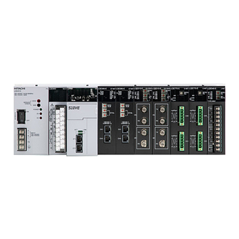
2.2.2 CPU unit configuration An S10VE system is made up of a mount base, power supply module, RI/O-IF module, CPU module, and PI/O modules. The mount base incorporates one PS slot (a dedicated slot for the power supply module), one IF slot (a dedicated slot for the RI/O-IF module), one CPU slot (a dedicated slot for the CPU module), and seven I/O slots. -
Page 62: Configuration Of Remote I/O Communication
2. Overview 2.2.3 Configuration of remote I/O communication The S10VE system can use an RI/O-IF module to perform remote I/O communication on a maximum of two lines (see Figure 2-3). The maximum length of each line is 300 m by remote I/O cable alone, extendable to a maximum of 3.3 km using remote I/O optical adapters. - Page 63 - The CPU module of the S10VE system does not perform external notification if the remote I/O line times out. It is the responsibility of the user to use a program that monitors the system register at the control cycle level and identifies when a timeout occurs.
-
Page 64: System Components
5 ET.NET LQE260-E communication that conforms to the IEEE802.3i (10BASE-T) or IEEE802.3u (100BASE-TX) specification. A dedicated option module for the S10VE that allows data sharing through memory transfer between CPU units. 6 OD.RING LQE510-E For I/O data, the maximum size of shared data is 4,096 points. For word data, the maximum size is 4,096 words. - Page 65 8 J.NET LQE540-E This module allows the S10VE to connect to a network that complies with this standard, and perform data communication with all manner of station devices. A dedicated option module for the S10VE that complies with the DeviceNet standard.
-
Page 66: Pi/O Units And Peripherals
2.3.3 PADT PADT (Programming and Debugging Tools) is a programming tool used to make, test, run, and troubleshoot application programs for the S10VE system. The PADT is a personal computer with the required software such as BASE SYSTEM/S10VE installed. The required specifications for the personal computer that serves as the PADT are as follows:... - Page 67 This page is intentionally left blank.
-
Page 68: Specifications
3. Specifications 3. Specifications Table 3-1 General specifications Item Specification Remarks 0 to 55°C Temperature variation of no Operating temperature more than 10°C per hour Storage temperature -20 to 75°C 10 to 90% RH (whether operational or Condensation must be Relative humidity non-operational) strictly avoided. -
Page 69: Table 3-2 Mount Base Specifications
3. Specifications Table 3-2 Mount base specifications Item Specification Remarks Model HSC-1770 Slot PS slot Power supply module installation slot IF slot RI/O-IF module installation slot CPU slot CPU module installation slot I/O slot Option module or PI/O module installation slot For details about the modules that can (maximum of 7) be installed and the restrictions that... -
Page 70: Table 3-4 Cpu Module Specifications
3. Specifications Table 3-4 CPU module specifications (1/3) Item Specification Remarks Model LQP600 Number of I/O points Maximum 2,048 points Ladder Supported diagrams Programming languages HI-FLOW Supported Supported Ladder 77 types instructions Instructions Application 141 types instructions Size 128 MB Main Backup None... - Page 71 3. Specifications Table 3-4 CPU module specifications (2/3) Item Specifications Remarks Ladder Internal register (R) 4,096 points function Keep relay (K) 4,096 points Timer (T) 2,048 points, ON-delay, time setting (0.1 to 999.9 s) One shot (U) 256 points, one-shot multivibrator time setting (0.1 to 999.9 s) Counter (C) 256 points, up-down counter...
- Page 72 3. Specifications Table 3-4 CPU module specifications (3/3) Item Specification Remarks Tool interface Ethernet Ethernet Number of channels 2 channels (ports are provided on the communication front of the module) Number of sockets 255 per unit Communication 10 Mbps/100 Mbps speed (auto-negotiation) Dielectric strength...
-
Page 73: Table 3-5 Ri/O-If Module Specifications
3. Specifications Table 3-5 RI/O-IF module specifications Item Specification Remarks Model LQE950 Line speed 768 kbps Number of lines 2 lines Number of Maximum of 12 units per line connected units Number of Maximum of 64 words (1,024 points) per line transferred words Insulation method Transformer insulation... -
Page 74: Table 3-6 Primary Battery Specification
3. Specifications Table 3-6 Primary battery specification Item Specification Remarks Product type Lithium manganese oxide battery Model HDC5200 Output voltage 3 V (approx.) Capacity 550 mAh or greater At delivery Replacement cycle Within 5 years... - Page 75 This page is intentionally left blank.
-
Page 76: Using The S10Ve System
4. Using the S10VE System 4. Using the S10VE System The following lists the procedures related to use of the S10VE system, and where in this manual each procedure is explained. Reference locations: Procedures: Overview, Specifications, Warranty Chapter 1: Usage Notes... - Page 77 This page is intentionally left blank.
-
Page 78: Part Names And Functions
5. Part Names and Functions 5. Part Names and Functions 5.1 Mount base (HSC-1770) Figure 5-1 shows the external dimensions of the 7-slot mount base. Table 5-1 lists the part names and explains the functions of each part. (1) External dimensions Front 437.0 mm 418.0 mm... -
Page 79: Table 5-1 Names And Functions Of 7-Slot Mount Base Parts
5. Part Names and Functions (2) Part names and functions Table 5-1 Names and functions of 7-slot mount base parts Name Function (1) PS (power supply) slot A slot in which the power supply module is installed. A slot in which the RI/O-IF module is installed. (2) IF slot You do not need to install an RI/O-IF module if the system will not communicate by remote I/O. -
Page 80: Power Supply Module (Lqv410)
5.2 Power supply module (LQV410) Figure 5-2 shows the external dimensions of the power supply module. Table 5-2 lists the part names and explains the functions of each part. (1) External dimensions HITACHI LQV410 100-120VAC 144VA 50/60Hz 100-110VDC 132W DC5V... - Page 81 5. Part Names and Functions WARNING ● To avoid electric shock, take the following precautions: - Do not touch the power supply terminals while input power is present. - Before wiring the power supply, make sure that no voltage is applied to the power cable. - Attach the terminal cover as soon as you finish wiring the power supply.
-
Page 82: Cpu Module (Lqp600)
5. Part Names and Functions 5.3 CPU module (LQP600) Figure 5-3 shows the external dimensions of the CPU module. Table 5-3 lists the part names and explains the functions of each part. (1) External dimensions 7 mm or less 155.2 mm 57.0 mm LQP600 C P U R U N... -
Page 83: Table 5-3 Names And Functions Of Cpu Module Parts
(3) Part names and functions Table 5-3 Names and functions of CPU module parts Name Function An indicator that shows the operating status of the S10VE system. Indicator For details, see Chapter 10. Menu keys that allow you to navigate through various settings. -
Page 84: Table 5-5 Combination Settings Of The Et St.no. (Ethernet Station Number Setting) Switch
5. Part Names and Functions Table 5-5 Combination settings of the ET ST.No. (Ethernet station number setting) switch Setting value Description The Ethernet ports operate using the following fixed IP addresses: CH1: 192.192.192.1 CH2: 192.192.193.1 Other than the The Ethernet ports operate using the IP addresses you have set. above For details about how to set IP addresses, see 8.4.2.5 Network configuration. -
Page 85: Figure 5-5 Rear View Of The Cpu Module
5. Part Names and Functions (6) Rear view Although BATT EN is indicated on the case, this function is not used. BATT EN Figure 5-5 Rear view of the CPU module... -
Page 86: Ri/O-If Module (Lqe950)
5. Part Names and Functions 5.4 RI/O-IF module (LQE950) Figure 5-6 shows the external dimensions of the RI/O-IF module. Table 5-7 lists the part names and explains the functions of each part. (1) External dimensions 21.5 mm or less 140.2 mm 34.0 mm RI/O-IF LQE950... -
Page 87: Figure 5-7 Terminal Block Arrangement Of Ri/O-If Module
5. Part Names and Functions (3) Terminal block layout PCsOK RI/O STOP STOP /RUN Ω Ω Ω RI/O Ω RI/O RI/O RI/O Figure 5-7 Terminal block arrangement of RI/O-IF module (4) Signal names and their functions Table 5-8 Terminal signal names and functions Terminal Signal Purpose... -
Page 88: Installation
6.2 Grounding The PCs panel that incorporates the S10VE must be welded to the steel frame of a building that provides class D grounding with the ground resistance of 100Ω or less. If this is not achievable, ground the panel by connecting it to a grounding rod driven into the earth. -
Page 89: Grounding The Cabinets
6. Installation 6.3 Grounding the cabinets When installing multiple cabinets in a row, daisy-chain the grounding cables as shown in Figure 6-2, and connect the last grounding cable to ground via a ground bar. Cabinet 1 Cabinet 2 Cabinet 3 Cabinet grounding point Insulating plate... - Page 90 6. Installation ■ Why is grounding necessary? - The failure of a transformer or other device might cause high voltage power to travel from a high-voltage device to a low-voltage device. In this situation, a ground connection prevents harm to the operator by electric shock.
-
Page 91: Mounting Clearances
6.4 Mounting clearances To ensure normal operation of the S10VE, you must provide air apertures with air filters at the top and bottom of the cabinet. You must also provide the clearances shown in Figure 6-4 between the cabinet and each unit. -
Page 92: External Dimensions Of Mount Base
Figure 6-5 shows the external dimensions of the mount base. For details about external dimensions of option modules, see the following manuals: - S10VE User's Manual Option OD.RING (LQE510-E) (manual number SEE-1-101) - S10VE User's Manual Option J.NET (LQE540-E) (manual number SEE-1-102) - S10VE User's Manual Option D.NET (LQE770-E) (manual number SEE-1-103) -
Page 93: Attaching The Mount Base
6. Installation 6.6 Attaching the mount base Secure the mount base to the upright surface of the cabinet as shown in Figure 6-6. Take care not to install the mount base facing upward, downward, or sideways. The modules are designed to achieve optimal heat dissipation when the mount base is secured to the upright surface of the cabinet. -
Page 94: Attaching Modules
6. Installation 6.7 Attaching modules After attaching the mount base to the cabinet, mount the individual modules to the mount base. Before attaching a module for the first time, remove the connector caps attached to the connectors on the mount base. - Page 95 6. Installation WARNING ● To avoid accident or electric shock, turn off the power switch on the power supply module before removing or installing a module. CAUTION ● Make sure that the screws are securely tightened. Failing to do so can cause smoke, fire, or malfunction, or cause the module to fall.
-
Page 96: Connecting The Primary Battery
6. Installation 6.8 Connecting the primary battery The following explains how to connect the primary battery of the S10VE CPU module. You must connect the primary battery before mounting the CPU module to the mount base. (1) Remove the primary battery cover from the left side of the CPU module by pulling on the tab. -
Page 97: Mounting Modules
6. Installation 6.9 Mounting modules Figure 6-9 illustrates how modules are mounted in the system. PS slot: Used to mount the power supply module. CPU slot: Used to mount the CPU module. I/O slots: Used to mount option modules or PI/O modules (a maximum of 7). IF slot: Used to mount the RI/O-IF module. -
Page 98: Restrictions On Mounting Option Modules
6. Installation 6.10 Restrictions on mounting option modules Restrictions apply to the mounting of option modules in terms of current consumption and communication times. The following explains the restrictions that apply when mounting option modules. (1) Restrictions on the number of option modules that can be mounted Table 6-1 shows the maximum number of option modules that can be mounted to a CPU unit. -
Page 99: Restrictions On Mounting Pi/O Modules To The Cpu Unit
6. Installation 6.11 Restrictions on mounting PI/O modules to the CPU unit Observe the following restrictions when mounting PI/O modules to the CPU unit: (1) Restrictions when mounting PI/O modules to the CPU unit - If option modules and PI/O modules are mounted to the CPU unit, arrange the modules in such a way that each is grouped with its own kind. - Page 100 6. Installation (c) When mounting analog modules to the same CPU unit as PI/O modules with a voltage of 100 V AC/48 V DC or higher, leave at least one empty slot between the analog modules and the PI/O modules. PI/O modules Analog with voltage of...
-
Page 101: Table 6-2 Restrictions On Number Of Pi/O Modules
6. Installation (2) Restrictions on the number of PI/O modules mounted to a CPU unit Table 6-2 shows the maximum number of PI/O modules that can be mounted to a CPU unit. Table 6-2 Restrictions on number of PI/O modules Maximum number of Name Model... -
Page 102: Current Consumption Calculation Table
6. Installation 6.12 Current consumption calculation table Table 6-3 shows the current consumption values for each module. A system is only viable if the total of the current values of its modules is less than the current capacity of the power supply. - Page 103 This page is intentionally left blank.
-
Page 104: Wiring
Table 7-1 lists the specifications for communication cables, power cables, and ground cables. Table 7-2 lists the cables we recommend. For details on how to wire a particular option module, see the manual for that option module. S10VE User's Manual Option OD.RING ( (manual number SEE-1-101) LQE510-E) S10VE User's Manual Option J.NET... -
Page 105: Table 7-1 Cable Specifications
0.75SQ LF × CO-EV-SB 1P 0.3SQ LF Medium distance (maximum 200 m per line) CO-EV-SB 1P × Manufactured by Hitachi Metals, Ltd. 0.18SQ LF Short distance (maximum 100 m per line) × 0.3SQ LF Manufactured by Hitachi Metals, Ltd. CO-SPEV-SB(A) 1P... -
Page 106: Wiring Standards
7.2 Wiring standards This section explains the wiring standards for the S10VE. 7.2.1 Terminal block and solderless terminals Figure 7-1 to Figure 7-5 show the terminal block and solderless terminals used with the S10VE. ■ 18-point terminal block Solderless terminal type: M3... -
Page 107: Figure 7-3 4-Point Terminal Block
7. Wiring ■ 4-point terminal block Solderless terminal type: M3 Applicable module name: Power supply (100 V AC or DC) Applicable module model: LQV410 Tightening torque: 0.6 N-m 41.5 4-M3 Unit:mm Figure 7-3 4-point terminal block ■ Compatible solderless terminals You must use M3 terminals (such as V1.25-3 and 1.25-YS3A) for the solderless terminals. -
Page 108: Attaching The Terminal Block
7. Wiring 7.2.2 Attaching the terminal block Attach the terminal block (18-point) by performing the steps explained in this section. Failing to follow the correct procedure might cause incomplete connections or damage to the terminal block. Note that the 11-point and 4-point terminal blocks are permanently fixed to the module and cannot be removed. -
Page 109: Power Supply Wiring
7. Wiring 7.3 Power supply wiring The input power supply of the S10VE must be insulated from the control power supply by an electrostatic- shielded insulating transformer. Figure 7-6 and Figure 7-7 show the wiring configuration when the insulating transformer is installed on the power distribution panel and the S10VE panel (PCs panel), respectively. -
Page 110: Figure 7-8 Example Of Internal Panel Wiring
7. Wiring ■ Example of internal panel wiring CPUユニット CPU unit PI/Oユニット PI/O unit 以上 2 mm or more 以上 2 mm or more TB (terminal block) TB(端子台) シールド Shield ground アース 盤アース Panel ground 静電シールド付き Electrostatic-shielded 絶縁トランス insulating transformer 床とは絶縁してください。... -
Page 111: Ground Wiring
Keep the LG and FG separate to prevent one from interfering with the other. ● The cabinet grounding point must be provided with class D grounding with the ground resistance of 100Ω or less. - Example of the mount base (model: HSC-1770) RI/O-IF HITACHI LQP600 LQE950 RI/O-IF LQE510-E OD.RING LQE510-E OD.RING LQE770-E D.NET... -
Page 112: Table 7-3 List Of Ground Wiring Requirements
7. Wiring Table 7-3 List of ground wiring requirements Name Item Description Power supply FG terminal grounding Connect the FG terminals of adjacent modules together in a daisy chain, and then connect the end of the daisy chain to the FG terminal of the mount base (wire diameter: 2 mm or more). -
Page 113: Wiring The Power Supply Module
7. Wiring 7.5 Wiring the power supply module Figure 7-10 shows the wiring of the power supply module. Figure 7-11 shows the input terminal connections. HITACHI LQV410 100-120VAC 144VA 50/60Hz 100-110VDC 132W DC5V SERVICE CHECK POWER AC 100 V to 120 V, 50/60 Hz... -
Page 114: Figure 7-12 Power Module Wiring In High-Noise Environment
7. Wiring In high-noise environments, insert an insulating transformer or noise filter as shown in Figure 7-12. HITACHI LQV410 100-120VAC 144VA 50/60Hz 100-110VDC 132W DC5V SERVICE CHECK POWER Insulating INPUT 100-120VAC transformer 100-110VDC or noise filter 警告 WARNING 感電危険触れるな Connected to the FG terminal of the... -
Page 115: Wiring For External I/O Signals Of The Ri/O-If Module
7. Wiring 7.6 Wiring for external I/O signals of the RI/O-IF module Figure 7-13 and Figure 7-14 show the wiring for the external I/O signals of the RI/O-IF module. 7.6.1 Wiring for PCsOK signal Figure 7-13 shows the wiring for the PCsOK signal. ■... -
Page 116: Wiring For Ri/O Stop And Cpu Stop/Run Signals
7. Wiring 7.6.2 Wiring for RI/O STOP and CPU STOP/RUN signals Figure 7-14 shows the wiring for the RI/O STOP and CPU STOP/RUN signals. ■ 100 V DC power supply RI/O-IF LQE950 RI/O STOP (STOP when ON) STOP/RUN (STOP when ON) RI/O STOP (A1) STOP/RUN (A2) Twisted pair cable... -
Page 117: Wiring For Remote I/O
7. Wiring 7.7 Wiring for remote I/O This section explains how to connect the remote I/O cables. 7.7.1 Connecting the remote I/O cables ● An RI/O-IF module is equipped with two remote I/O cable connection ports (RI/O-1 and RI/O-2). You can connect a maximum of 12 PI/O units to each port. -
Page 118: Examples Of Improper Remote I/O Wiring
7. Wiring 7.7.2 Examples of improper remote I/O wiring Wiring the remote I/O cables in any of the incorrect ways shown in Table 7-4 can distort the waveform of the signal on the lines, causing communication errors. Take care to wire the cables correctly. Table 7-4 Correct and incorrect remote I/O wiring CPU unit PI/O unit... -
Page 119: Examples Of Cable Wiring
SHD (A9) Remote I/O station module Remote I/O station module (not terminated) (not terminated) RI/O LQS010 RI/O LQS010 RI/O RI/O ST.NO ST.NO HITACHI HITACHI HSC-1000 HSC-1000 128M 128M RI/O1A (A4) RI/O1A (A4) RI/O1B (A5) RI/O1B (A5) SHD (A6) SHD (A6) HOLD HOLD Ω... -
Page 120: Figure 7-17 Wiring Example When Using Hsc-1000 And Hsc-2100 Series Remote I/O Stations In
Like the S10V, the S10VE can connect to HSC-1000 series and HSC-2100 series remote I/O stations. The S10VE can also connect to the remote I/O stations designed for common use by the S10V and S10mini. Figure 7-17 shows a wiring example for these scenarios. -
Page 121: Setting Terminating Resistance
7. Wiring 7.7.4 Setting terminating resistance When using the designated cables, connect the terminals as shown in Table 7-5. This will terminate the lines with a built-in 100Ω or 150Ω resistor (or an externally wired 100Ω resistor on the RI/O-IF module). To terminate with a resistance other than 100Ω... - Page 122 7. Wiring WARNING ● To avoid electric shock, do not touch the terminal block terminals or connector pins while the power is ● To avoid electric shock and fire, wiring must be carried out by a person with practical experience who has undergone the appropriate training and is able to recognize the hazards presented by the work.
-
Page 123: Connecting The Remote I/O Cable Shields
7. Wiring 7.7.5 Connecting the remote I/O cable shields This section explains how to connect the shields of the remote I/O cables that connect to RI/O-IF modules. ■ Connecting the shields of remote I/O cables Connect the shields of the cables connected to remote I/O ports 1 and 2 to the respective SHD terminals on the terminal block. -
Page 124: Figure 7-19 Examples Of Connections Between Panels Installed In A Row
7. Wiring FG terminal of the Remote I/O cable mount base Panel 1 Panel 2 RI/O FG terminal of the FG terminal of the I/O power supply module mount base terminal FG terminal When implementing single-ended Connect the FG grounding, do not connect the FG terminal of the RI/O-IF terminal of the remote I/O station module to the FG... -
Page 125: Figure 7-20 Example Of Connections Between Different Panels
7. Wiring (2) Example of connections between different panels When connecting the remote I/O cable between different panels, ground the shield of the remote I/O cable at one end on the RI/O-IF module side. Connect the FG terminal of the RI/O-IF module to the FG terminal of the power supply module and the FG terminal of the mount base. -
Page 126: Wiring The Ethernet Cabling
7. Wiring 7.8 Wiring the Ethernet cabling When using only one channel for Ethernet communication in the CPU module, connect the Ethernet cable to the ET1 connector of the CPU module. This is to allow the PADT to connect to the ET2 connector during maintenance. LQP600 C P U R U N STBY... -
Page 127: Example Of Duct Wiring
HC Area for wiring external cables inside the cabinet Duct Duct S10VE Wiring duct at bottom of unit Front Figure 7-23 Example of wiring ducts carrying cables for different circuit classifications (top view) 7-24... -
Page 128: Working With Connector Caps
7. Wiring 7.10 Working with connector caps Each connector is fitted with a connector cap before shipping. Remove the cap before wiring the connector. The removed connector cap must be stored. Leave the caps on connectors that will not be used. Figures 7-24 and 7-25 show where connector caps are fitted to the product during shipping. - Page 129 This page is intentionally left blank.
-
Page 130: Tools
Windows®. 8.1.3 Restrictions on connection configuration of PADT and S10VE The following restrictions apply when connecting the PADT and the S10VE by means other than a direct Ethernet LAN cable connection: Connection via a hub Use a switch. -
Page 131: Constructing The System
8. Tools 8.2 Constructing the system 8.2.1 Constructing a new system The following explains the procedure for creating a new project and setting up a new S10VE system. START Install BASE SYSTEM See 8.2.3 Installing the tools Start the S10VE... - Page 132 (7) Restarting the S10VE Turn off the power switch of the power supply module of the S10VE, set the switches on the CPU module according to the following table, and then turn on the power supply module again. Switch name...
-
Page 133: Replacing The Cpms
8. Tools 8.2.2 Replacing the CPMS The following explains how to open an existing project and replace the CPMS of the S10VE. START Start the S10VE Start BASE SYSTEM Open a project Change the connection-destination PCs Download CPMS (1) Start the S10VE Turn on the power switch on the power supply module of the S10VE. -
Page 134: Installing The Tools
In this case, uninstall the tool you were installing and exit all Windows® programs. Then, install the tool again. For details on how to uninstall a tool, see 8.2.3.3 Uninstalling individual tools. ● Do not install an S10VE tool to any of the following folders, which are protected by User Account Control: - Program file folder (for example, C:¥Program Files) -
Page 135: Installing Individual Tools
Log on as an account with administrator privileges when installing the tools. (1) To install the HI-FLOW SYSTEM/S10VE tool, double-click setup.exe in the folder S789803 on the HI-FLOW SYSTEM/S10VE installation CD. The setup.exe file of each tool is located in a different folder. -
Page 136: Figure 8-3 Installshield Wizard Complete Window
BASE SYSTEM/S10VE. If you log on with a user account other than that used for installing BASE SYSTEM/S10VE, the installed program might not appear in the program menu. In this case, log off and log on again with the administrator account that was first created on your PADT, uninstall the installed program, and then install the program again. -
Page 137: Uninstalling Individual Tools
8.2.3.3 Uninstalling individual tools You can uninstall tools from the Control Panel or from the basic installation set. The following procedure uses the example of uninstalling BASE SYSTEM/S10VE from the Control Panel. Log on as an account with administrator privileges when uninstalling tools. -
Page 138: Figure 8-6 Uninstall Complete Message (For Uninstallation Of Running Tool)
8. Tools If you uninstall a tool without shutting it down first, the Uninstall Complete message shown in Figure 8-6 appears instead of that shown in Figure 8-5. Select whether you want to restart the computer now or later, and then click Finish. Figure 8-6 Uninstall Complete message (for uninstallation of running tool) If you restart a computer on which RPDP is installed, an RPDP internal command displays the error message shown in Figure 8-7. -
Page 139: Reinstalling Individual Tools
8. Tools 8.2.3.4 Reinstalling individual tools To reinstall a tool, you must first uninstall it. You can then install it again. For details on how to uninstall a tool, see 8.2.3.3 Uninstalling individual tools. For details on how to install a tool, see 8.2.3.2 Installing individual tools. -
Page 140: Installing And Uninstalling Tools From The Basic Installation Set
(1) To install or uninstall a tool from the basic installation set, double-click the SETUP.exe file on the CD (BASE SET/S10VE). (2) When you double-click SETUP.exe, the following message might appear. Click Yes to acknowledge the message and begin the setup process. - Page 141 8. Tools (4) The list of tools contains the following information: Title Description P.P. name The name of the tool. P.P. type The type of the tool. Ver-Rev(CD) The version and revision number of the tool to be installed from the CD. The version and revision number of the tool that is installed on the PC.
-
Page 142: Starting The System
RPDPusers group. (1) Starting BASE SYSTEM normally To start BASE SYSTEM in Windows® 7, from the Start menu, select All Programs, Hitachi S10VE, BASE SYSTEM, and then S10VEBASE. In Windows® 10, from the Start menu, select Hitachi S10VE and then S10VEBASE. - Page 143 8. Tools (2) Starting BASE SYSTEM using temporary administrator privileges In Windows® 7, from the Start menu, select Hitachi S10VE and BASE SYSTEM, and then right- click S10VEBASE. From the right-click menu, select Run as administrator. In Windows® 10, from the Start menu, select Hitachi S10VE and then right-click S10VEBASE.
-
Page 144: Starting Ladder Diagram System
For details on how to start LADDER DIAGRAM SYSTEM from BASE SYSTEM, see 8.4.4.1 Program menu: LADDER. Figure 8-11 Screen displayed when LADDER DIAGRAM SYSTEM starts For details on how to use LADDER DIAGRAM SYSTEM, see the S10VE Software Manual Operation Ladder Diagram System for Windows® (manual number SEE-3-131). 8-15... -
Page 145: Starting Hi-Flow System
For details on how to start HI-FLOW SYSTEM from BASE SYSTEM, see 8.4.4.2 Program menu: HI- FLOW. Figure 8-12 Screen displayed when HI-FLOW SYSTEM starts For details on how to use HI-FLOW SYSTEM, see the S10VE Software Manual Operation HI-FLOW for Windows® (manual number SEE-3-132). 8-16... -
Page 146: Starting The Setup Tools
8. Tools 8.3.1.4 Starting the setup tools The setup tools offer parameter setup functions for individual option modules. You can start each setup tool from BASE SYSTEM. (1) Starting setup functions From the BASE SYSTEM main menu, select Program and then Setting Tool. The Setting Tool window appears. -
Page 147: Exiting Tools
8. Tools 8.3.2 Exiting tools The following explains how to exit each tool. 8.3.2.1 Exiting BASE SYSTEM From the BASE SYSTEM main menu, select Project and then End. 8.3.2.2 Exiting the LADDER and HI-FLOW systems From the LADDER DIAGRAM SYSTEM or HI-FLOW SYSTEM main menu, select File and then End. 8.3.2.3 Exiting setup tools In the Setting main window of the setup tool, click Close. -
Page 148: Base System
8. Tools 8.4 BASE SYSTEM 8.4.1 Layout of the BASE SYSTEM main window The following figure (Figure 8-14) shows the layout of the BASE SYSTEM main window. This window consists of a main menu and a status bar. Main menu Status bar Figure 8-14 Layout of the BASE SYSTEM main window 8.4.1.1 Main menu... -
Page 149: Status Bar
8. Tools 8.4.1.2 Status bar The status bar displays the following information: PCs No. Communication type IP address Figure 8-15 Status bar ● PCs No.: The PCs number of the project that is currently open, as a four-digit decimal number. ●... -
Page 150: Project Functions
8. Tools 8.4.2 Project functions Project functions are available from the Project menu. Figure 8-16 Window after clicking the Project menu The following table lists and describes the project functions: Table 8-2 List of Project menu items Category Description Level 1 Level 2 Level 3 Project... -
Page 151: Project Menu: New
8. Tools 8.4.2.1 Project menu: New Use this menu item to create a project file containing the information required to set up PCs. To create a project that uses C mode, one way is to log on as an administrator with RPDP installed and start BASE SYSTEM normally. -
Page 152: Figure 8-19 Error Message When Rpdp Is Not Installed
8. Tools (3) Set the following PCs parameters: - PCsNo. A number (0 to 9998) that identifies the PCs. This field is blank by default. The PCs number is also the level at which BASE SYSTEM manages projects (sites). - Comment Set a comment (maximum 128 characters) that helps identify the PCs. -
Page 153: Figure 8-21 Overwrite Confirmation Message
8. Tools (b) Overwriting an existing project If a project with the specified PCs number already exists, a message appears asking you to confirm that you want to overwrite the project. Figure 8-21 Overwrite confirmation message Click Yes to overwrite the project. Click No to cancel saving the project. -
Page 154: Figure 8-23 Message Asking Whether You Want To Create A Project With An Existing Pcs Number
8. Tools (d) Saving a project under an existing PCs number (overwrite existing project) If you change the PCs number of an open project to a number that is already assigned to an existing project, the following message appears: Figure 8-23 Message asking whether you want to create a project with an existing PCs number If you click Yes, the system deletes the existing project with the specified PCs number, makes a copy of the open project, and creates another project using the settings of the open project. -
Page 155: Figure 8-25 Error Message Indicating Lack Of Site Update Permission
8. Tools (5) To update the CPMS file of the project to the currently installed file, click CPMS Update. If C-mode usage is enabled, the RPDP site is also updated. If any of the following apply, an error message dialog box appears: - The logged-in user (does not apply to the administrator) does not belong to the RPDPusers group. -
Page 156: Project Menu: Open
8. Tools 8.4.2.2 Project menu: Open Use this menu item to open a project file. To open a project with C-mode usage enabled, start BASE SYSTEM after logging on as the administrator or a user who belongs to the RPDPusers group in an environment with RPDP installed. -
Page 157: Project Menu: Close
8. Tools (4) To open a project, select the PCs number of the project you want to open from the list, and then click Open. The project opens and the Properties window (Figure 8-17) appears. If a Properties window is already open, the Properties window for the selected project will appear when you close the open window. -
Page 158: Project Menu: Delete
8. Tools 8.4.2.4 Project menu: Delete Use this menu item to delete a project file. To delete a project that has C-mode usage enabled, you need to log on as an administrator with RPDP installed and start BASE SYSTEM normally, or log on as a user who belongs to the RPDPusers group and use temporary administrator privileges to start BASE SYSTEM. -
Page 159: Figure 8-29 Deletion Confirmation Message
8. Tools (3) To delete a project, select the PCs number of the project you want to delete from the list, and then click Delete. A message appears asking you to confirm that you want to delete the project. Figure 8-29 Deletion confirmation message Click Yes to delete the project. -
Page 160: Project Menu: Set Network
8. Tools 8.4.2.5 Project menu: Set Network The following explains how to set the network information for the CPU module and the ET.NET module. If the station number of the CPU module is 0xFF, the system operates with 192.192.192.1 as the IP address of the CPU module's built-in port Ethernet 1, and 192.192.193.1 as the IP address of its built- in port Ethernet 2. -
Page 161: Network Configuration Of Cpu Built-In Ethernet
8. Tools 8.4.2.5.1 Network configuration of CPU built-in Ethernet Set the network information of the CPU module. If you intend to use only one Ethernet channel, use Ethernet 1. However, you must also set up Ethernet 2 so that the PADT can connect to the CPU module to perform maintenance. When using two Ethernet channels for control purposes, you will need to reconfigure Ethernet 1 or Ethernet 2 if the need arises to connect the PADT via the CPU built-in Ethernet. -
Page 162: Figure 8-31 Message Asking For Confirmation Of Ethernet Station Number Overwrite
8. Tools (3) To set network information, enter the information for the selected network and then click Set. The information entered in the Set Network window when you click the Set button takes effect when you click the Write PCs button. - Select Network Select the type of network you want to configure. -
Page 163: Figure 8-32 Reset Confirmation Message
8. Tools (4) To delete network information, select the network in Select Network whose information you want to delete, and then click Delete. The displayed network information is cleared. If you click the Write PCs button after clicking Delete, the network information set on the PCs is deleted. -
Page 164: Figure 8-34 Reset Failed Message
8. Tools If the reset fails, BASE SYSTEM displays a message reporting that the reset was not successful. Figure 8-34 Reset failed message In this case, you will need to reset the PCs manually. There are two ways to manually reset the PCs: - Turn the CPU RUN/STOP switch from RUN to STOP and then back to RUN. -
Page 165: Net Configuration
8. Tools 8.4.2.5.2 ET.NET configuration (1) Set the network information for ET.NET. From the main menu, select Project, Set Network, and then ET.NET. (2) The Set Network (ET.NET) window appears. Figure 8-35 Set Network (ET.NET) window (3) Select the ET.NET module (main or sub) whose network you want to configure from the Select Network drop-down list. -
Page 166: Figure 8-36 Route Information Window
8. Tools Figure 8-36 Route Information window Set the Setting Routes Num, Network Address, and Gateway IP Address values. You can define a maximum of 32 routes. After entering the information, click OK to return to the Set Network (ET.NET) window. If you click Cancel, the settings you entered are discarded and you are returned to the Set Network (ET.NET) window. -
Page 167: Figure 8-38 Overwrite Confirmation Message
8. Tools Select the number of the module whose parameters you want to set, and then click OK. The network information you set in the Set Network (ET.NET) window is written to the selected module. If you click Cancel, you are returned to the Set Network (ET.NET) window without any settings being written to the PCs. -
Page 168: Figure 8-40 Reset Confirmation Message
8. Tools - After writing to the PCs, the system displays a message that notifies you that the PCs will be reset and asks for confirmation (Figure 8-40). Figure 8-40 Reset confirmation message Click OK to reset the PCs. If you click Cancel, the PCs are not reset. - If BASE SYSTEM successfully resets the PCs, it displays a message to that effect (Figure 8-41). -
Page 169: Figure 8-43 Open Window (Set Network (Et.net))
8. Tools (5) To display the network information registered on the PCs, click the Read PCs button in the Set Network (ET.NET) window. The system reads the information from the PCs and displays it on the screen. (6) To use network information that has been saved to a file, select the ET.NET module (main or sub) whose network you want to configure from the Select Network drop-down list, and then click the File open button. -
Page 170: Figure 8-44 File Open Window
8. Tools Figure 8-44 File open window View the file name and comment in the File open window to make sure that the file is the correct one. If it is the correct file, click File open. You are returned to the Set Network (ET.NET) window, which now displays the network information read from the file. -
Page 171: Figure 8-46 Option Module Parameter Setup List Window (Deletion)
8. Tools (7) To delete network information, click the Delete button in the Set Network (ET.NET) window. The Option module parameter setup list window (deletion) (Figure 8-46) appears. If you click Cancel, you are returned to the Set Network (ET.NET) window without any option module parameters being deleted. -
Page 172: Figure 8-48 Save As Dialog Box
8. Tools (8) To save the network information you input to a file, click the File save button in the Set Network (ET.NET) window. A Save As dialog box appears. Figure 8-48 Save As dialog box In the Save As dialog box, specify the name of the file to which you want to save the network information. -
Page 173: Figure 8-49 File Save Window
8. Tools Figure 8-49 File save window In the File save window, enter a comment about the file as needed. You can use a maximum of 512 characters. You can also change the PCs number in this window. Click File save to save the file with the specified file name. The file will now be available to select when you click the File open button, or can be used by functions that send and receive data. - Page 174 8. Tools (9) You can output network information in CSV format by clicking the CSV Output button in the Set Network (ET.NET) window. The format of the CSV file is as follows: ET.NET YYYY/MM/DD hh:mm:ss ---- (1) File Name=XXXXXXXXXXXXXXXXXXXXXXX ---- (6) (Connection Type) ---- (2) PCsNo.: XXXX...
- Page 175 8. Tools Description of CSV file contents (1) Date and time The date and time the file was created, in the format YYYY/MM/DD hh:mm:ss Ethernet (2) Connection type (3) Project number (PCs number) Output as a decimal number (4) Module type For the main ET.NET module: ET.NET(Main) For the ET.NET sub-module: ET.NET(Sub) (5) Network information for CH1 and CH2...
-
Page 176: Project Menu: Download Cpms
8. Tools 8.4.2.6 Project menu: Download CPMS Use this menu item to download CPMS to the CPU module. Confirm the following before downloading CPMS: [1] The PADT is not connected to the ET.NET module. [2] The RUN/STOP switch of the CPU module is set to RUN. (1) From the main menu, select Project and then Download CPMS. -
Page 177: Figure 8-53 Progress Window (Download)
8. Tools (4) If CPMS has already been downloaded to the module, the system displays a message asking you to confirm that you want to reset the PCs (Figure 8-32). Click OK to begin the download process. To cancel the download, click Cancel. If the download fails to start, an error message appears indicating that the data could not be read. -
Page 178: Figure 8-55 Rom Load Failure Error Message
(6) When the CPMS download has completed, a Close button appears in the progress window. The system assigns the PCs number of the open project to the PCs. Information about the S10VE system is loaded into BASE SYSTEM and displayed in the status bar. (7) Click Close to close the Download CPMS window. -
Page 179: Project Menu: End
8. Tools 8.4.2.7 Project menu: End Use this menu item to exit the application and output an operation log. (1) From the main menu, select Project and then End. (2) The confirmation message shown in Figure 8-56 might appear. If it appears, you might have clicked Cancel when asked by BASE SYSTEM to confirm a reset that was required to apply settings to PCs. -
Page 180: Online Functions
8. Tools 8.4.3 Online functions Online functions are available from the Online menu. Figure 8-58 Window after clicking the Online menu The following table lists and describes the online functions: Table 8-3 List of Online menu items Category Description Level 1 Level 2 Level 3 Online... -
Page 181: Online Menu: Change Pcs
8. Tools 8.4.3.1 Online menu: Change PCs Use this menu item to set the communication type used for connections with the PCs. (1) From the main menu, select Online and then Change PCs. (2) The Change PCs window appears. Figure 8-59 Change PCs window (3) Set the communication type (station number and IP address). -
Page 182: Online Menu: Display Pcs Status And Change Pcs Status
8. Tools 8.4.3.2 Online menu: Display PCs STATUS and Change PCs STATUS Use this menu item to display and change the status of the PCs. (1) From the main menu, select Online and then Display PCs STATUS and Change PCs STATUS. (2) The PCs Status window appears. - Page 183 8. Tools PROTECT MODE Sets whether to operate arithmetic functions in protection mode. Status Description Ladder arithmetic functions operate in protection mode. Ladder arithmetic functions operate without protection mode. When protection mode is enabled, the ladder program stops if an arithmetic function running on the SH processor performs write access to any of the areas listed in the following table.
- Page 184 8. Tools Category Symbol Remarks BIN 7SEG BIN ASCII ASCII BIN Decode Encode Square root Sine Cosine Tangent Arcsine ASIN Arccosine ACOS Arctangent ATAN Exponent Natural logarithm Clear XCLR YCLR GCLR RCLR KCLR TCLR UCLR CCLR VCLR ECLR FCLR 8-55...
- Page 185 8. Tools Category Symbol Remarks TCP communication TPOP TPOP TCLO TRCV TSND UDP communication UCLO URCV USND The scale conversion (SCL) function also runs on the SH processor when the Long data type is specified as an argument. All arithmetic functions operate on the SH processor when index specification is specified as an argument.
- Page 186 8. Tools RUN LED Shows the state of the RUN LED of the CPU module. For details about the LED states, see 5.3 CPU module and 11.4.2 State transitions. Status Description The RUN LED of the CPU module is lit. The RUN LED of the CPU module is off.
-
Page 187: Online Menu: Data Send/Receive
8. Tools ALARM LED Shows the state of the ALARM LED of the CPU module. For details about the LED states, see 5.3 CPU module and 11.4.2 State transitions. Status Description The ALARM LED of the CPU module is lit. The ALARM LED of the CPU module is off. -
Page 188: Sending Data
8. Tools 8.4.3.3.1 Sending data Perform the following procedure to send option module settings to the PCs: (1) Select the area number to which you want to send the settings, and then click Send. You can send settings to an area whose module name is blank, or which is assigned the same module type and module number as the option module settings you are sending. -
Page 189: Figure 8-65 Error Message Displayed When Pcs Numbers Do Not Match
8. Tools When you click Send, the Send Data window closes. The system checks the data to be sent, after which data transmission begins. If you click Cancel, data transmission is canceled and the Send Data window closes. If the check of the data to be sent reveals an error, data transmission is canceled. - PCs number If the PCs number in the file differs than that of the destination area, the system displays the following error message. -
Page 190: Figure 8-68 Progress Window (Sending Data)
8. Tools (4) The following window appears displaying the progress of data transmission. Figure 8-68 Progress window (sending data) If you click Cancel, data transmission is interrupted and the Cancel button in the progress window changes to a Close button. Towards the end of transmission, you will reach a point where you are no longer able to cancel the data transmission. -
Page 191: Receiving Data
8. Tools 8.4.3.3.2 Receiving data Perform the following procedure to download option module settings data to a file: (1) Select the area number whose settings you want to receive, and then click Receive. (2) A Save As window appears. Specify the name of the file where you want to save the data. Figure 8-69 Save As window (Data Send/Receive) When you click Save, the Save As window closes and the Receive Data window appears. -
Page 192: Figure 8-71 Progress Window (Receiving Data)
8. Tools - PCs number Specify the number that identifies the PCs in a range from 0 to 9999. By default, the PCs number is that of the open project. You can use the number 9999 as a wildcard. If you use a file saved with the PCs number 9999 when sending data to PCs, the data will be sent without checking the PCs number of the destination area. -
Page 193: Comparing Data
8. Tools 8.4.3.3.3 Comparing data Perform the following procedure to compare the option module settings data in a file with the corresponding data on PCs: (1) Select the area number whose settings you want to compare, and then click Compare. (2) An Open window appears. -
Page 194: Figure 8-74 Message Indicating That Comparison Was Successful
8. Tools (5) When data comparison has completed, the Cancel button in the progress window changes to a Close button. If the data is consistent, the system displays a message indicating the data comparison was successfully completed (Figure 8-74). If there are differences in the data, the system displays a second format of a message indicating that the data is inconsistent (Figure 8-77). -
Page 195: Figure 8-78 Format Of Comparison Error Data File
8. Tools M>: Memory data F>: File data Memory address H0010 0000 M> 1234ABCD 0001000 00000034 00000000 F> 1234ABCD 0002000 00001F00 00000000 H0010 0100 M> 00000001 FFFFF00 00000000 00000000 F> C0A8FA01 FFFFF00 00000000 00000000 Figure 8-78 Format of comparison error data file Explanation of comparison error data file format Data is compared in units of four longwords. -
Page 196: Deleting Data
8. Tools 8.4.3.3.4 Deleting data Perform the following procedure to delete option module settings data from the PCs. Note that this function deletes option module settings from the CPU module, not from the option module itself. The option module concerned will continue to operate until removed. (1) Select the area number whose settings you want to delete, and then click Delete. -
Page 197: Online Menu: Backup, Restore, Backup Save Data Comparison
8. Tools 8.4.3.4 Online menu: Backup, Restore, Backup save data comparison Use these menu items to back up and restore data on PCs, and to compare backup data against the data on the PCs. For details about each of these functions, see 8.5 BACKUP RESTORE SYSTEM. 8.4.3.5 Online menu: Remote Reset Use this menu item to reset PCs. -
Page 198: Online Menu: Remote Restart
8. Tools 8.4.3.6 Online menu: Remote Restart Use this menu item to restart stopped PCs in RUN mode. Confirm the following before performing a remote restart: - The PADT is not connected to an ET.NET module. You can remotely restart a CPU module whose CPU RUN/STOP switch is set to STOP. However, the CPU module will not restart in RUN mode. -
Page 199: Online Menu: Data Clear
8. Tools 8.4.3.7 Online menu: Data Clear Use this menu item to clear the backup memory of the PCs. The backup memory is the area from H00480600 to H04FF1FFF. The following table lists the area cleared by the data clear function: Table 8-4 Data clear area Address Description... -
Page 200: Figure 8-85 Error Detected Message
8. Tools (3) If a communication line error occurs during the memory clear operation, the system displays a message indicating that an error was detected (Figure 8-85). Check the communication line between the PADT and PCs, and then initiate the data clear operation again. -
Page 201: Program Functions
8. Tools 8.4.4 Program functions Program functions are available from the Program menu. Figure 8-86 Window after clicking the Program menu The following table lists and describes the program functions: Table 8-5 List of Program menu items Category Description Level 1 Level 2 Level 3 Program... -
Page 202: Program Menu: Ladder
8. Tools 8.4.4.1 Program menu: LADDER Use this menu item to start LADDER DIAGRAM SYSTEM. (1) From the main menu, select Program and then LADDER. (2) LADDER DIAGRAM SYSTEM starts. 8.4.4.2 Program menu: HI-FLOW Use this menu item to start HI-FLOW SYSTEM. (1) From the main menu, select Program and then HI-FLOW. -
Page 203: Figure 8-88 Error Message Displayed When Selected Tool Cannot Be Run
8. Tools (3) The system display a list of tools installed on the PADT. The following table explains the items displayed in the list: Table 8-6 Items displayed in Setting Tool window Item Description Name The name of the tool installed on the PADT. Model The type of the tool installed on the PADT. -
Page 204: Setting Functions
8. Tools 8.4.5 Setting functions Setting functions are available from the Setting menu. Figure 8-89 Window after clicking the Setting menu The following table lists and describes the setting functions: Table 8-7 List of Setting menu items Category Description Level 1 Level 2 Level 3 Setting... -
Page 205: Setting Menu: Set Time
8. Tools 8.4.5.1 Setting menu: Set Time Use this menu item to display or set the clock of the CPU module. (1) From the main menu, select Setting and then Set Time. (2) The Set Time window appears. By default, the system retrieves and displays the time from the CPU module. -
Page 206: Ras Functions
8. Tools 8.4.6 RAS functions RAS functions are available from the RAS menu. Figure 8-91 Window after clicking the RAS menu The following table lists and describes the RAS functions: Table 8-8 List of RAS menu items Category Description Level 1 Level 2 Level 3 Module List... -
Page 207: Ras Menu: Module List
8. Tools 8.4.6.1 RAS menu: Module List Use this menu item to display a list of modules and microprograms installed in the system. (1) From the main menu, select RAS and then Module List. (2) The Module List window appears. Figure 8-92 Module List window (3) The Module List window displays the version and revision number of the CPMS and firmware (Firm). -
Page 208: Ras Menu: Error Log Display
8. Tools 8.4.6.2 RAS menu: Error Log Display Use this menu item to display log information related to errors that occurred on the PCs. A maximum of two fatal errors and 32 nonfatal errors are displayed. (1) To display error log information for the ET.NET module or for the CP side of the CPU module, from the main menu, select RAS, Error Log Display, and then CP Error Log Display. -
Page 209: Table 8-10 Module Names That Can Be Selected In Display Error Log Cp Window
8. Tools (3) In the Display Error log CP window, you can select whether to display error information for the CPU module or for an ET.NET module. The Display Error log HP window only displays error information for the CPU module. Table 8-10 Module names that can be selected in Display Error log CP window Item Description... - Page 210 8. Tools The information the error code represents is output in the following format: Panic log: [*] ******** (PC=********, FADR=********) (1) Error severity type [F]: Fatal error [FU]: Built-in subroutine error (2) Error message (3) Program counter (4) Fault address Non-panic logs: First pattern: [*] ******** (UNO=**, DEV=********) (TN=***) (SLOT=**)
- Page 211 8. Tools Second pattern: %****-*-****-**** (1) (2) (3) (1) The system that detected the error. CPMS: CPMS (basic OS) LNET: RCTLNET (network driver) NX: NXACP (autonomous distributed platform) MSxx: Middleware (where xx is a number from 01 to 16) USxx: Application software (where xx is a number from 01 to 16) (2) Error severity type F: Fatal error E: Error...
-
Page 212: Displaying Error Log Details
8. Tools 8.4.6.3 Displaying error log details (1) In the Display Error log CP window or Display Error log HP window, click Error Log Detail. (2) The Error Log Detail window appears. Figure 8-95 Error Log Detail window (3) The following shows the items displayed in the Error Log Detail window. For an explanation of the information displayed as detail data, see 8.4.6.2 RAS menu: Error Log Display. - Page 213 8. Tools ■ System that detected error CPMS: CPMS (basic OS) LNET: RCTLNET (network driver) NX: NXACP (autonomous distributed platform) MSxx: Middleware (where xx is a number from 01 to 16) USxx: Application software (where xx is a number from 01 to 16) ■...
-
Page 214: Ras Menu: Mcs
If you select the Compatible PI/O check box, the register address changes to an S10mini-compatible address or an S10V/S10VE extended address. PI/O names in the register are displayed as both S10mini-compatible addresses and S10VE extended addresses regardless of whether the Compatible PI/O check box is selected. - Page 215 8. Tools (6) To monitor the memory contents at the displayed addresses, click Start. The system begins to monitor the memory contents, and the Start button changes to a Stop button. (7) To stop monitoring, click Stop. The system stops monitoring the memory contents, and the Stop button changes to a Start button.
-
Page 216: Ras Menu: Display Performance
8. Tools 8.4.6.5 RAS menu: Display Performance Use this menu item to display the CP and HP load factors. (1) From the main menu, select RAS and then Display Performance. (2) The Performance window appears. Figure 8-98 Performance window (3) In the Measurement Unit Time field, specify the measurement cycle of the load factor. Specify 1 or a multiple of the sequence cycle (maximum of 100), in seconds. - Page 217 8. Tools The format of the CSV file is as follows: CP,HP XXXXXXXXXX,YYYYYYYYYY XXXXXXXXXX,YYYYYYYYYY XXXXXXXXXX,YYYYYYYYYY XXXXXXXXXX,YYYYYYYYYY XXXXXXXXXX: CP side load factor (expressed as floating point numeral from 0 to 100%) YYYYYYYYYY: HP side load factor (expressed as floating point numeral from 0 to 100%) 8-88...
-
Page 218: Ras Menu: Event Register
8. Tools 8.4.6.6 RAS menu: Event Register Use this menu item to display the ON/OFF state of event registers (E coil) E0000 to E01FF. (1) From the main menu, select RAS and then Event Register. (2) The Event Register Monitor window appears. Figure 8-99 Event Register Monitor window (3) Click Start Monitoring to start monitoring the event registers. -
Page 219: Ras Menu: Network Information
8. Tools 8.4.6.7 RAS menu: Network Information Use this menu item to display the network information of the CPU module and ET.NET module. (1) From the main menu, select RAS and then Network Information. (2) The Display Status of Network window appears. Figure 8-100 Display Status of Network window (3) Select the network whose network information you want to display from the Selection of the network drop-down list. -
Page 220: Figure 8-101 Save As Window
8. Tools (4) Select the particular aspect of network information that you want to display by clicking the applicable tab. The Display Status of Network window contains the following tabbed pages: Table 8-13 Tabbed pages in Display Status of Network window Item Description Active socket... -
Page 221: Ras Menu: Ethernet Communication Of Trace Log
For details on traces, see Appendix F. List of DHP Codes in the S10VE Software Manual CPMS General Description and Macro Specifications (manual number SEE-3-201). For details on error codes, see the list of detailed result codes in 2.7.2 Usage in the S10VE Software Manual Programming Ladder Diagram System for Windows® (manual number SEE-3-121). -
Page 222: Figure 8-103 Display Ethernet Communication Of Trace Log (Socket Handler) Window
For details on traces, see Appendix F. List of DHP Codes in the S10VE Software Manual CPMS General Description and Macro Specifications (manual number SEE-3-201). For details on error codes, see the list of detailed result codes in 2.7.2 Usage in the S10VE Software Manual Programming Ladder Diagram System for Windows® (manual number SEE-3-121). -
Page 223: Figure 8-104 Save As Window
8. Tools (5) To save the displayed Ethernet communication trace log information to a text file, click Save. Select a folder and specify a file name in the Save As window that appears, and then click Save to save the trace log information to the file. -
Page 224: Ras Menu: Dhp Information
8. Tools 8.4.6.9 RAS menu: DHP Information Use this menu item to display a window in which you can set the DHP logging mode and view DHP trace information. (1) From the main menu, select RAS and then DHP Information. Figure 8-105 DHP Information window (2) The Module Name drop-down list shows the name of the CPU module, ET.NET main module, and ET.NET sub-module installed in the PCs. -
Page 225: Figure 8-106 Display Dhp Trace Cp Side Window
8. Tools (6) The Display DHP trace window appears. Figure 8-106 Display DHP trace CP side window When displaying DHP trace information for the HP side, the window title is Display DHP trace HP side. When displaying DHP trace information for the ET.NET module (main or sub), the window title is Display DHP trace ET.NET(Main/Sub). -
Page 226: Ras Menu: Autosave
8. Tools 8.4.6.10 RAS menu: AutoSave Use this menu item to create an autosave file and a fault analysis information file. Confirm the following before using the AutoSave function: [1] The PADT is not connected to an ET.NET module. [2] The CPMS has been downloaded. [3] The CPU module is in STOP mode. -
Page 227: Figure 8-110 Executing Window
8. Tools - To save an autosave file, perform the following procedure: [1] In the file save window, specify a name for the autosave file (XXXX.atdmp). [2] Click Save. The file save window closes and the Executing window appears (Figure 8-110). [3] To close the file save window, click Cancel. -
Page 228: Figure 8-112 Structure Of Autosave File
8. Tools Structure of autosave file Figure 8-112 shows the information output to the autosave file. An autosave file has the extension .atdmp, and is in binary format. Autosave file 0x0000 0000 Main memory map Autosave file 0x0000 header 0x0008 (512 bytes) CPMS for HP 0x0000 0200... -
Page 229: Figure 8-113 Format Of Fault Analysis Information File
8. Tools Structure of fault analysis information file Figure 8-113 shows the information output to the fault analysis information file. A fault analysis information file has the extension .txt, and is in text format. Description Title 1 FATAL error log information OSCB information SYSCB information HAICB information... - Page 230 8. Tools Details of fault analysis information file The following shows, in detail, the information output to the fault analysis information file. The numbers in parentheses correspond to the numbers in the No. column in Figure 8-113. (1) Title 1 AAA BBB CC DD:EE:FF System trouble information HHHH...
- Page 231 8. Tools AAA: The day of the week on which the fault analysis information file was created. BBB: The month in which the fault analysis information file was created. CC: The day on which the fault analysis information file was created. DD: The time (hour) when the fault analysis information file was created.
- Page 232 8. Tools (3) OSCB information <OSCB> ctnr=xxxxxxxx tcnt=xxxxxxxx astcb=xxxxxxxx ascnt=xxxxxxxx boot time : xxx xxx xx xx:xx:xx xxxx idlesec =xxxxxxxx idlensec=xxxxxxxx ulsubctl=xxxxxxxx tcba =xxxxxxxx syscba =xxxxxxxx ucba =xxxxxxxx trba =xxxxxxxx rscba =xxxxxxxx rsvba =xxxxxxxx dhpa =xxxxxxxx uslcba =xxxxxxxx wdtdata =xxxxxxxx logtbl =xxxxxxxx tmcb =xxxxxxxx...
- Page 233 8. Tools (4) SYSCB information <SYSCB> cpu=x cpmsver=xxxx procno=x pptype=xxxxxxxx realmem=xxxxxxxx site : xxxx tod=x syntim=xxxxxxxx maxtn=xxx maxun=xx maxtm=xxx maxrsv=xx log_buf_top=xxxxxxxx log_buf_size=xxxxxxxx dhp_buf_top=xxxxxxxx dhp_buf_size=xxxxxxxx mbuf =xxxxxxxx portflg =xxxxxxxx multi_sys=X sysno=x maxpu=X stopall=xx cyclctl=xxxxxxxx netconf =xxxxxxxx backup_top=xxxxxxxx pte=xxxxxxxx oswork =xxxxxxxx network =xxxxxxxx iproute =xxxxxxxx...
- Page 234 8. Tools (5) HAICB information <HAICB> puvars =xxxxxxxx machine=xxxxxxxx puvars: The address of the puvar table. machine: The address of the machine table. (6) Memory patrol information <MEMPATTBL> mempat_addr=xxxxxxxx mempat_cnt =xxxxxxxx mempat_log =xxxxxxxx mempat_idx =xxxxxxxx mempat_err =xxxxxxxx mempat_total=xxxxxxxx tv_sec[0]=xxxxx = xxxxxxxx ecc3coradr = xxxxxxxx ecc3cordat = xxxxxxxx ecc3status ecc3cordat_ul = xxxxxxxx ecc3corsum = xxxxxxxx tv_sec[1]=xxxxx...
- Page 235 8. Tools (8) DHP information DHP TIME EVENT DATA1 DATA2 DATA3 DATA4 DATA5 X XX.XXXXXX XXXXXXXXX XXXXXXXX XXXXXXXX XXXXXXXX XXXXXXXX XXXXXXXX (20 sets of information) DHP: The display number of the DHP trace information. TIME: The trace time (displayed to the microsecond). EVENT: The trace point type.
- Page 236 8. Tools (14) UCB information *** UCB = xxxx *** dev =xxxxxxxx =xxxxxxxx conf=xxxxxxxx tout =xxxxxxxx status=xxxx flags=xxxx ext =xxxxxxxx ioerba=xxxxxxxx (24 sets of information) UCB = xxxx: The USB number. dev: The device number. dva: The device address (unused). conf: Configuration data.
- Page 237 TOP: The start address of the shared resource (GLB). LAST: The end address of the shared resource (GLB). (20) $VER information No PPName PPversion SInumber loadpkg Time XX-XX XX/XX/XX 1 CPMS/S10VE XX:XX:XX XX-XX XX/XX/XX 2 RCTLNET/S10VE XX:XX:XX XX-XX XX/XX/XX 3 RPDP/S10VE XX:XX:XX (Maximum of 64 sets of information) No: The number of registered pieces of tool information.
- Page 238 8. Tools (22) Bus error count information S10VE(MP) mwdpe =xxxxxxxx =xxxxxxxx trnsto=xxxxxxxx mape=xxxxxxxx mrdpe =xxxxxxxx =xxxxxxxx brqto =xxxxxxxx rtryov=xxxxxxxx mserr=xxxxxxxx nruto =xxxxxxxx S10VE(SPU) mwdpe =xxxxxxxx =xxxxxxxx trnsto=xxxxxxxx mape=xxxxxxxx mrdpe =xxxxxxxx =xxxxxxxx brqto =xxxxxxxx rtryov=xxxxxxxx mserr=xxxxxxxx nruto =xxxxxxxx mwdpe: The number of times WDPE reception was detected while operating as a bus master.
-
Page 239: Cpms Debugger Functions
8. Tools 8.4.7 CPMS debugger functions CPMS debugger functions are available from the CPMS Debugger menu. Figure 8-114 Window after clicking the CPMS Debugger menu The following table lists and describes the CPMS debugger functions: Table 8-16 List of CPMS Debugger menu items Category Description Level 1... -
Page 240: Cpms Debugger Menu: Task Abort
8. Tools 8.4.7.1 CPMS Debugger menu: Task Abort Use this menu item to inhibit a task from starting. (1) From the main menu, select CPMS Debugger, and then Task Abort. (2) The Task Abort window appears. Figure 8-115 Task Abort window Task Number Specify the task number of the task whose start you want to suppress, as a number from 1 to 229. -
Page 241: Cpms Debugger Menu: Display Task Status
8. Tools 8.4.7.2 CPMS Debugger menu: Display Task Status Use this menu item to display the status of registered tasks. (1) From the main menu, select CPMS Debugger and then Display Task Status. (2) The Task Status window appears. Figure 8-117 Task Status window (3) Click Refresh to display a list of registered tasks and their status in the Task Registration area. -
Page 242: Table 8-18 Task Statuses
8. Tools Table 8-18 Task statuses Shown as Description DORMANT Start is suppressed IDLE Waiting to start READY Running or waiting to execute WAIT Waiting for an event SUSPENDED Execution is suppressed (4) Click Close to close the Task Status window. 8-113... -
Page 243: Cpms Debugger Menu: Initialize Task
8. Tools 8.4.7.3 CPMS Debugger menu: Initialize Task Use this menu item to initialize the task environment. Confirm the following before initializing the task environment: [1] The PADT is not connected to an ET.NET module. [2] CPMS has been downloaded. [3]The hardware CPU RUN/STOP switch is set to RUN. -
Page 244: Figure 8-120 Error Message Displayed When Data Cannot Be Read
8. Tools (4) If the environment can be initialized, the system displays a message asking you to confirm that you want to reset it (Figure 8-32). To begin initializing the task environment, click OK. If you click Cancel, initialization of the task environment is canceled. If initialization of the task environment fails to start, an error message appears indicating that the data could not be read. - Page 245 8. Tools For details about the ROM load operation, see SDRAM state during ROM load operation in 8.5.5 Scope of backup, restoration, and comparison. When initialization has completed, a Close button appears in the progress window. The CPU enters STOP mode while the task environment is being initialized. When initialization is complete, the CPU returns to RUN mode.
-
Page 246: Backup Restore System
8. Tools 8.5 BACKUP RESTORE SYSTEM 8.5.1 Backup You can use BACKUP RESTORE SYSTEM to back up the data on the CPU module. Confirm the following before backing up the CPU data: [1] The PADT is not connected to an ET.NET module. [2] The hardware CPU RUN/STOP switch is set to RUN. -
Page 247: Figure 8-123 Backup Window
8. Tools (2) The Backup window appears. Figure 8-123 Backup window (3) The Name field displays the default name of the backup folder. Specify the name of the folder in which you want to save the backup data (the backup folder). You can enter a maximum of 200 characters. -
Page 248: Figure 8-125 Overwrite Confirmation Message
8. Tools (5) Enter a comment in the Comment field, if needed. (6) If you want the system to verify the received backup data to confirm that it has been saved correctly, select the Comparison of save data check box. (7) Click Execute to begin the backup process. -
Page 249: Figure 8-127 Backup Cancelation Confirmation Message
8. Tools If you click Cancel, a message appears asking you to confirm that you want to cancel the backup operation. Figure 8-127 Backup cancelation confirmation message If you click Yes in this dialog box, a message appears asking you to confirm that you want to change the CPU mode to RUN (Figure 8-128). -
Page 250: Figure 8-130 Stop Recovery Guidance Message
8. Tools Figure 8-130 STOP recovery guidance message Click OK to dismiss the message. The State of backup window appears indicating that backup was canceled. Click Close in this State of backup window to return to the Backup window (Figure 8-123). (9) If you selected the Comparison of save data check box, the system compares the backup data it receives with the data on the PCs. -
Page 251: Figure 8-132 Data Comparison Cancelation Confirmation Message
8. Tools Figure 8-132 Data comparison cancelation confirmation message If you respond Yes to this message, a CPU RUN confirmation message (Figure 8-128) appears. When you click OK in the CPU RUN confirmation message, the State of backup window (Figure 8-133) appears. -
Page 252: Figure 8-134 State Of Backup Window (When No Inconsistencies Are Found)
8. Tools (10) The behavior after the system has received the backup data and compared it with the data on the PCs (if the comparison option is enabled) depends on the state the CPU module is in when the backup process starts. -
Page 253: Figure 8-136 Format Of Compare_Error.txt File
8. Tools (b) If the CPU module is in STOP mode when you start the save process, it remains in STOP mode. The message providing guidance on STOP recovery appears. Click OK to dismiss the message. If the comparison does not find any inconsistencies, the system displays the State of backup window that indicates data comparison was successful (Figure 8-134). - Page 254 8. Tools (11) Click Close in the Backup window (Figure 8-123) to complete the backup process and return to BASE SYSTEM. If the data comparison found inconsistencies in the backup data, you will need to perform the backup process again. Notice ●...
-
Page 255: Restore
8. Tools 8.5.2 Restore You can use BACKUP RESTORE SYSTEM to restore backup data to the CPU module. CPMS might not be installed on the CPU module to which you want to restore the backup data, such as when the CPU module is new. In this case, from the BASE SYSTEM main menu, select Online and then Change PCs. -
Page 256: Figure 8-138 Restore Window
8. Tools (2) The Restore window appears. Figure 8-138 Restore window (3) The Position field displays the path of the backup folders. From the list of folders, select the backup folder whose backup data you want to restore. The Execute button becomes available when you select a folder from which backup data can be restored. -
Page 257: Figure 8-139 Message Asking Whether To Continue Restoration
8. Tools (7) If the PCs to which you are restoring the data has a different PCs number from the PCs where the backup was taken, the system displays a message asking you to confirm that you want to continue. If you click OK, the system proceeds with the restoration process. -
Page 258: Figure 8-142 Confirmation Message For Pcs Number Change
8. Tools ● If the State of Restore window does not appear during the restoration process, it might be hidden behind the active window. To check whether this is the case, align your mouse pointer with the BASE SYSTEM icon on the Windows taskbar. ●... -
Page 259: Figure 8-144 Cpu Run Confirmation Message
8. Tools (12) The behavior after the system has sent the data and compared it with the local data (if the comparison option is enabled) depends on the state of the CPU module when the restoration process was started. If the CPU was in RUN mode when the restoration process started, go to (a). As with CPU module replacement, if the CPU was in STOP mode when the restoration process started, go to (b). -
Page 260: Figure 8-146 State Of Restore Window (When No Inconsistencies Are Found)
8. Tools (13) If the comparison does not find any inconsistencies, the system displays a window indicating that data comparison completed successfully. Click Close. You are returned to the Restore window. Figure 8-146 State of Restore window (when no inconsistencies are found) If the comparison finds inconsistencies in the data, the system displays a window indicating that inconsistent data was found and creates the comparison error data file COMPARE_ERROR.txt (Figure 8-136) in the specified folder. -
Page 261: Figure 8-148 Confirmation Message For Overwriting Comparison Error Data File
8. Tools Figure 8-148 Confirmation message for overwriting comparison error data file Notice ● To avoid malfunction, do not place the CPU module in RUN mode if the data comparison has found the data to be inconsistent. In this case, perform the restoration process again, and do not turn the system on and off again until the issue is resolved. -
Page 262: Backup Save Data Comparison
8. Tools 8.5.3 Backup save data comparison You can use BACKUP RESTORE SYSTEM to compare the data in a backup file with the data on the CPU module. Confirm the following before comparing the backup file with the data on the CPU module: [1] The PADT is not connected to an ET.NET module. -
Page 263: Figure 8-150 Backup Save Data Comparison Window
8. Tools (2) The Backup save data comparison window appears. Figure 8-150 Backup save data comparison window (3) The Position field displays the path of the backup folders. Select the backup folder whose backup data you want to compare. The Execute button becomes available when you select a folder whose backup data can be compared. -
Page 264: Figure 8-151 Message Asking Whether To Continue Backup Data Comparison
8. Tools Figure 8-151 Message asking whether to continue backup data comparison (7) After approximately 30 seconds, comparison of the backup data begins, and the State of Backup save data comparison window appears (Figure 8-152). The Close button is unavailable until data comparison has completed. -
Page 265: Figure 8-154 State Of Backup Save Data Comparison Window (When Data Comparison Is Canceled)
8. Tools Figure 8-154 State of Backup save data comparison window (when data comparison is canceled) (9) If comparison of the backup data has completed and no inconsistencies were found, the State of Backup save data comparison window appears as follows (Figure 8-155). Figure 8-155 State of Backup save data comparison window (when no inconsistencies are found) (10) If comparison of the backup data reveals inconsistencies with the data on the PCs, the State of Backup... -
Page 266: Figure 8-157 Confirmation Message For Overwriting Comparison Error Data File
8. Tools If the comparison finds inconsistencies in the data, the system creates a comparison error data file (COMPARE_ERROR.txt) in the specified backup folder (Figure 8-136). If there is already a COMPARE_ERROR.txt file in the specified folder, the system displays a message asking you to confirm that you want to overwrite the existing file (Figure 8-157). - Page 267 8. Tools LED states during backup data comparison LED state State of backup data (CPU module) Description comparison STBY CPU STOP instruction The user has clicked OK in the CPU STOP confirmation issued message. Immediately after BLINK The user has just clicked the Execute button (ROM load execution operation is taking place).
-
Page 268: Duration Of Backup/Restoration Processes
8. Tools 8.5.4 Duration of backup/restoration processes The following table shows how long the system takes to perform backup, restoration, and backup data comparison. Use this as a general guide for real-world use. Each process can take more or less time depending on the performance of the PADT. The times in the table were measured on a PADT with the following specifications: Installed memory: 2 GB CPU: Core™... -
Page 269: Scope Of Backup, Restoration, And Comparison
When a ROM load operation takes place, the entire main memory is initialized. If you are using the S10 bus memory space shown in 3.1 Logical space in the S10VE Software Manual CPMS General Description and Macro Specifications (manual number SEE-3-201) as the user area, you can use the data transmit/receive function of LADDER DIAGRAM SYSTEM/S10VE to back up and restore the user area as needed. -
Page 270: Figure 8-158 Areas Subject To Rom Load Operation
The NX user buffer area (H0100 0000 to H01FF FFFF) was subject to backup operation in the S10V, but is not subject to backup operation in the S10VE. To back up or restore data in the NX user buffer area, use the data transmit/receive function of LADDER DIAGRAM SYSTEM/S10VE to select Save new (or Save) or Send in online mode. -
Page 271: Table 8-21 Scope Of Restoration
8. Tools (2) Scope of restoration Table 8-21 Scope of restoration Scope Purpose Remarks Memory Addresses Size type SDRAM HA400 4000 to HA400 407F 0.125 KB (128 bytes) OS firmware I/F HA400 C100 to HA400 DFFF 7.75 KB (7,936 bytes) RPDP usage area HA408 0000 to HAAFB FFFF 111.25 MB OS management... -
Page 272: Other Functions
8. Tools 8.6 Other functions 8.6.1 Operation history recording function The operation history recording function records the operation history of BASE SYSTEM. This function can record a maximum of 1,024 operation history items. When this number is reached, the system deletes old entries as it adds new ones. Operation history is saved to a file when BASE SYSTEM is shut down. -
Page 273: Table 8-23 Items In Operation Record File
8. Tools ■ List of operation history items The following table lists the operations that are recorded in the operation record file: Table 8-23 Items in operation record file (1/3) Menu item Format New (PCsNO=xxxx) Open Open (PCsNO=xxxx) Close Close (PCsNO=xxxx) Delete Delete (PCsNO=xxxx) Set Network... - Page 274 8. Tools Table 8-23 Items in operation record file (2/3) Menu item Button Format Property:Save Properties Save Property:CPMS Updating CPMS Update Property:Close Close Projects:Open Project List Open Projects:Close Close Projects:Delete Delete Network:Set Set Network Delete Network: Delete Network:Write PCs Write PCs Network:Close Close Download CPMS:Download...
- Page 275 8. Tools Table 8-23 Items in operation record file (3/3) Menu item Button Format DHP info:Select(CP) or (HP) DHP Information Select Restart DHP DHP info:Start logging Stop DHP logging DHP info:Stop Display DHP trace DHP info:Trace DHP info:Close Close AutoSave Close AutoSave:Close Task Abort:OK...
-
Page 276: Contents Of Cpms Files
8. Tools 8.7 Contents of CPMS files The following table explains the contents of the CPMS files loaded into the project when you click Save or CPMS Update in the Project window: Table 8-24 List of CPMS file contents File name Contents OSfile The CPMS itself, and its system tasks, system area, and so on. -
Page 277: Error Messages
(3) If the error occurs when displaying the Project List window: Make sure that the xml file in (2) exists for all PCs numbers set in the C:¥ S10VE ¥sysPcsCnt.txt file (the first line in sysPcsCnt.txt is the number of PCs numbers, and the second and subsequent lines are the PCs numbers themselves). - Page 278 Failed to reset PCs. Check the communication paths. Failed to read the IP information file for the Check the state of the C:¥ S10VE¥setipa_S10VE.def file. BASE SYSTEM. No IP address is set for the IP information Set the communication type again in the Change PCs window.
-
Page 279: Project Menu
Failed to create a project directory. Check the state of the C:¥S10VE directory. Failed to create a project file. Check the state of the C:¥S10VE¥xxxx folder (where xxxx is the PCs number). Failed to create C-mode use information. Contact the system administrator. -
Page 280: Table 8-28 Project List Window (Open)
Perform the operation as the administrator, or as a user who has administrator privileges and belongs to the RPDPusers group. Failed to update the IP information file for BASE Check the state of the C:¥S10VE¥setipa_S10VE.def SYSTEM. file. Failed to update the IP information file for RPDP. -
Page 281: Table 8-29 Project List Window (Delete)
Cannot delete the project because it is open. Close the project and then perform the operation again. Failed to delete the project directory. Check the state of the C:¥S10VE¥xxxx folder (where xxxx is the PCs number). Table 8-30 Close Error message... -
Page 282: Table 8-32 Download Cpms Window
(status error: status) Contact the system administrator. Failed to invoke svupdatesiteos command. Check whether the C:¥windows¥renix¥S10VE¥bin¥svupdatesiteo s.exe file exists. If this file does not exist, you will need to install RPDP. An error occurred in svupdatesiteos command. Check the error code in Table 8-55. If the error code is Error: error-code unknown, contact the system administrator. -
Page 283: Table 8-33 End
8. Tools Table 8-33 End Error message Action to take Failed to write data to the operation log. Check the state of the folder that contains the S10VEBASE.exe file. Operation log write right is not provided. Check whether you are able to write to the folder that contains the S10VEBASE.exe file. -
Page 284: Online Menu
Set the CPU RUN/STOP switch of the CPU module to Execute this operation with CPU RUN. RUN and then perform the operation again. Check the state of the C:¥S10VE¥setipa_S10VE.def Failed to update the IP information file for the BASE SYSTEM. -
Page 285: Table 8-35 Display Pcs Status And Change Pcs Status
8. Tools Table 8-35 Display PCs STATUS and Change PCs STATUS Error message Action to take Failed to get PCs status. Check the communication paths. Failed to change the specified PCs status. Check the communication paths. Check the state of the PCs. Cannot change the ALARM LED status. -
Page 286: Table 8-37 Backup, Restore, And Backup Save Data Comparison
8. Tools Table 8-37 Backup, Restore, and Backup save data comparison (1/2) Error message Action to take Failed in the CPU STOP processing. Check the communication paths. Also, check the error code Module: xr_rrw_stop in Table 8-48. If the error code is unknown, contact the Error: error-code system administrator. -
Page 287: Table 8-38 Data Clear
8. Tools Table 8-37 Backup, Restore, and Backup save data comparison (2/2) Error message Action to take A folder name is too long. Review the path and file name specified in the Position and Name fields, and then perform the backup operation again. ROM load went wrong. -
Page 288: Program Menu
8. Tools 8.8.4 Program menu Table 8-39 Program menu Error message Action to take Failed to run the HI-FLOW window program. Check whether the HI-FLOW SYSTEM software product is installed. Select a menu after installing P.P. of HI-FLOW Install the HI-FLOW SYSTEM software product. SYSTEM. -
Page 289: Ras Menu
8. Tools 8.8.6 RAS menu Table 8-42 Error log Error message Action to take Close the CP error log information window, and then Close the Display Error log CP window. execute this operation. Close the HP error log information window, and then Close the Display Error log HP window. -
Page 290: Cpms Debugger Menu
8. Tools 8.8.7 CPMS Debugger menu Table 8-45 Task Abort window Error message Action to take No task number is input. Enter a task number. Enter a task number. Enter a task number within a range of 1 to 229. Enter a number within the permitted range. -
Page 291: Table 8-46 Initialize Task Window
8. Tools Table 8-46 Initialize Task window Error message Action to take The OS initial information file has not been loaded. Click CPMS Update in the Properties window. Cannot execute with SW STOP. Execute this Set the CPU RUN/STOP switch of the CPU module to operation with SW RUN. -
Page 292: Rpc Error Messages
8. Tools 8.8.8 RPC error messages Table 8-47 RPC error messages Error message Action to take Line error (A signal was received.) If there is no issue with the communication paths, contact the system administrator. Line error (A timeout error occurred.) If there is no issue with the communication paths, contact the system administrator. -
Page 293: Error Codes
8. Tools 8.8.9 Error codes Table 8-48 xr_rrw_rpl_p, xr_rrw_rrb_p, xr_rrw_stop, and xr_rrw_grstart Error Nature of error Socket error IP address error Storage area address error (0 specified, dta) Storage area address error (0 specified, wka) Size error (0 KB or less, or 16 KB or more) Size error (non-longword size) Remote adapter type error Unable to allocate memory for frame creation... -
Page 294: Table 8-49 Svaddsite
8. Tools Table 8-49 svaddsite Error Nature of error There is an error in the definition file. The specified system construction environment could not be found. The project file could not be updated. Table 8-50 svupdatesiteos Error Nature of error Abnormal termination Data cannot be updated because the addresses of the user area of the base site overlap with those of the destination. - Page 295 This page is intentionally left blank.
-
Page 296: Settings
9. Settings 9. Settings 9.1 Setting items Table 9-1 and Table 9-2 list the settings that are available when using the S10VE system. Table 9-1 Hardware settings Module name Setting item Description of setting Reference CPU module CPU RUN/STOP Set using the CPU RUN /STOP switch of the CPU module. -
Page 297: Table 9-2 Software Settings
9. Settings Table 9-2 Software settings Unit name Setting item Description of setting Reference CPU unit PI/O installation Set whether PI/O modules are to be installed in the CPU unit. See 9.3.1 - When installing PI/O modules: Used - When not installing PI/O modules: No used Partition setting Set the I/O slots (partitions) into which I/O modules are to be See 9.3.2... - Page 298 9. Settings For details on how to configure a module installed in the PI/O unit, see the manual for that module: - S10mini Hardware Manual I/O Modules (manual number SME-1-114) - S10mini Hardware Manual D.Station (manual number SME-1-119) - HSC-2100 Hardware Manual I/O Modules (manual number SME-1-126)
-
Page 299: I/O Number Structure And Scope Of Allocation
9. Settings 9.2 I/O number structure and scope of allocation An I/O number identifies the I/O type of a PI/O module and the slot in which it is installed. Each I/O number is made up of five alphanumeric characters. The following figure explains the meaning of each digit: ■... -
Page 300: Setting Pi/O And Remote I/O
Use the ladder diagram system tool to set up the PI/O and remote I/O for the CPU unit. For details on how to connect and start this tool, see the S10VE Software Manual Operation Ladder Diagram System for Windows® (manual number SEE-3-131). -
Page 301: Partition Setting (Fix/Free)
X0AAA, and to output slots in the format Y0AAA. ■ CPU unit partition setting For details on how to set the partition setting of the CPU unit, see the S10VE Software Manual Operation Ladder Diagram System for Windows® (manual number SEE-3-131). -
Page 302: Table 9-3 Fix And Free Settings
9. Settings ■ Differences between FIX and FREE settings Table 9-3 FIX and FREE settings Setting item FREE From X0010 From Y0010 From X0010 To X0AAA From Y0010 To Y0AAA To Y0AAA To X0AAA CPU unit CPU unit RI/O RI/O Input or output Input modules Output modules... -
Page 303: Output Hold Setting For Digital Output Modules
■ Setting the number of I/O points of the CPU unit For details on how to set the number of I/O points of the CPU unit, see the S10VE Software Manual Operation Ladder Diagram System for Windows® (manual number SEE-3-131). -
Page 304: Table 9-4 Cpu Unit I/O Number Allocation And I/O Points Used (Partition Setting: Free, First I/O Number: 0000)
9. Settings ■ Relationship between I/O points and I/O numbers ● The following settings determine the prefix and range of the allocated I/O numbers: Prefix: The first three digits are determined by the station number setting. Range: Numbers are automatically allocated based on the number of I/O slots in the mount base, the number of I/O points, and the partition setting. -
Page 305: Table 9-5 Cpu Unit I/O Number Allocation And I/O Points Used (Partition Setting: Fix, First I/O Number: 0000)
9. Settings Table 9-5 CPU unit I/O number allocation and I/O points used (Partition setting: FIX, First I/O number: 0000) I/O points I/O numbers I/O points used per unit X area (input): 64 points Slot number Y area (output): 64 points Note that the first 16 points on the input I/O number side (X0000 to X000F) are invalid... -
Page 306: Ladder Synchronous/Asynchronous Mode Setting
Note: In synchronous mode, a sequence cycle cannot be shorter than a remote I/O cycle. ■ Setting synchronous or asynchronous mode For details on how to enable synchronous or asynchronous mode, see the S10VE Software Manual Operation Ladder Diagram System for Windows® (manual number SEE-3-131). -
Page 307: Remote I/O Optical Adapter Connection Setting
■ Setting the number of remote I/O points For details on how to set the number of remote I/O points, see the S10VE Software Manual Operation Ladder Diagram System for Windows® (manual number SEE-3-131). -
Page 308: Analog Module And Pulse Counter Module Settings
You can skip this setting if you want to use the analog module with the MODE1 setting. ■ Settings for analog modules and pulse counter modules For details on how to perform these settings, see the S10VE Software Manual Operation Ladder Diagram System for Windows® (manual number SEE-3-131). - Page 309 This page is intentionally left blank.
-
Page 310: Indicator
10. Indicator 10.1 Overview An indicator is provided on the front panel of the S10VE CPU module. This indicator provides the user with information about the operating status of the S10VE. You can also use the menu keys on the indicator panel to perform a number of tasks, including displaying the error state of the S10VE system and checking various settings. -
Page 311: Information Displayed On Indicator
10. Indicator 10.2 Information displayed on indicator Table 10-2 lists the information that can be displayed on the indicator. Table 10-2 Information displayed on indicator Description Display example Home position display L D R R U N Firmware version display F W V E R V E R OS version display... -
Page 312: Indicator Display Transitions
▲UP ●SET L E D C H K Indicator pattern display (see 10.4.5) ●ESC ▼DOWN (1) (2) #: Maintenance mode for Hitachi use (not disclosed to users) Figure 10-2 Indicator display transitions when CPU module is in STOP mode 10-3... -
Page 313: Figure 10-3 Indicator Display Transitions When Cpu Module Is In Run Mode
10. Indicator ▲UP Home position L D R R U N A L 9 0 0 2 E 0 0 0 0 ▲UP ▼DOWN R F W V E R Firmware version display (see 10.4.2) ●ESC ▲UP ▼DOWN R o S V E R OS version display (see 10.4.3) ●ESC ▲UP... -
Page 314: Explanation Of Displayed Information
10. Indicator 10.4 Explanation of displayed information 10.4.1 Home position display The home position is where the indicator displays the CPU module operating status, the E coil status, the CPU module alarm status, and the error status of option modules. The indicator automatically transitions to the next status display after two seconds. -
Page 315: Table 10-4 Minor Error Status Display
10. Indicator (2) E coil status display (available when the CPU module is in RUN mode) The system detects the E coil (display range from E0000 to E01FF) and sequentially displays each case of the E coil being ON. If the E coil is ON at multiple locations, the system displays the next case after cycling through the other events. -
Page 316: Firmware Version Display
10.4.2 Firmware version display The indicator displays the firmware version. The version number displayed on the indicator is the control number Hitachi assigns to the firmware. To display the firmware version: (1) With F W V E R displayed on the indicator, press the ◄L/►R toggle switch towards the ►R position. -
Page 317: Cpu Module Error Status Display
10. Indicator 10.4.4 CPU module error status display The indicator displays the error status of the CPU module. This includes the error status detected by firmware, and the error status detected by the OS. To display the error status of the CPU module: (1) With E R R S T S displayed on the indicator, press the ◄L/►R toggle switch towards the ►R position. -
Page 318: Table 10-7 Cpu Module Error Status Display
10. Indicator Interpreting the display ● Display of error status detected by firmware If the firmware has detected an error, the display alternates between E C F = m m and n n n n n n approximately every two seconds. The error code is the string of eight alphanumeric characters starting with m m and ending with n n n n n n. -
Page 319: Indicator Pattern Display (Available When Cpu Module Is In Stop Mode)
10. Indicator 10.4.5 Indicator pattern display (available when CPU module is in STOP mode) You can use this mode to make sure that the indicator is displaying characters and symbols correctly. To check the indicator pattern display: (1) If you press the SET switch while L E D C H K is displayed, " *+"... -
Page 320: Ladder Mode Display (Extended Menu)
10. Indicator Table 10-8 Indicator patterns Display Description The title of the menu for checking indicator pattern display. L E D C H K This item appears when the CPU module is in STOP mode. Display pattern 1 -./01 Display pattern 2 2 3 4 5 6 7 Display pattern 3 8 9 : ;... -
Page 321: Pcs Number Display (Extended Menu)
10. Indicator 10.4.7 PCs number display (extended menu) The indicator displays the PCs number assigned to the CPU module. To display the PCs number: (1) With P C S N o displayed on the indicator, press the ◄L/►R toggle switch towards the ►R position to display the PCs number (for example P N 0 0 0 0). -
Page 322: Operation
You can start and stop the system over the network by using a PC. For details on the specific procedure, see the software manual for the application you are using. • S10VE Software Manual Programming Ladder Diagram System for Windows® (manual number SEE-3- 121) •... -
Page 323: User Program Operations
11. Operation 11.2 User program operations The following describes the operation of user programs (ladder, HI-FLOW, and C language). For ladder programs and HI-FLOW, user programs operate on a sequence cycle specified by the user. C- language programs (user tasks) operate asynchronously with ladder programs and HI-FLOW. In addition, if you are using both ladder programs and HI-FLOW, HI-FLOW processing occurs after ladder program processing. -
Page 324: Figure 11-3 Operation When The Sequence Cycle Is Longer Than The Program Processing Time
For detailed information about specific applications, see the software manual for the application you are using. • S10VE Software Manual Programming Ladder Diagram System for Windows® (manual number SEE-3-121) • S10VE Software Manual Programming HI-FLOW for Windows® (manual number SEE-3-122) •... -
Page 325: Remote I/O Operation
11. Operation 11.3 Remote I/O operation The following describes the remote I/O communication operation of the RI/O-IF module (model: LQE950). If you are running a CPU unit with a PI/O module installed, the PI/O module of the CPU unit operates in the same manner as the PI/O module of the PI/O unit. -
Page 326: Synchronous And Asynchronous Ladder Operation
11. Operation 11.3.2 Synchronous and asynchronous ladder operation You can specify settings for synchronous or asynchronous ladder processing with remote I/O transfer input and output. Figure 11-6 describes synchronous and asynchronous ladder operation. When ladder processing is asynchronous, ladder processing and remote I/O transfer operations are performed individually. -
Page 327: Processing Time
11. Operation 11.3.3 Processing time Figure 11-7 shows a representation of the processing time until an external output signal is output from the output module, after an external input signal is input into the input module. If the external input signal, the remote I/O line transfer operation, and the ladder processing are performed asynchronously, the sum total of (1) through (4) is not always accurate, but this value can serve as a rough estimate. - Page 328 11. Operation For an input transfer, the external input signal and the remote I/O transfer operation are not synchronized. For this reason, the input value of the input module is sometimes determined immediately after the transfer starts. In such a case, the correct input value is not transmitted to the CPU module until the next transfer cycle, which results in a required transfer time of about twice as much (1.6 to 44 ms).
-
Page 329: Remote I/O Transfer Points And Transfer Areas
11. Operation 11.3.4 Remote I/O transfer points and transfer areas You can specify one of the following for the remote I/O transfer points: 64, 128, 256, 512, 1024, 1536, and 2048 points. Figure 11-8 shows the remote I/O transfer point settings and transfer areas. The transfer areas for settings ranging from 64 points to 256 points are shown in the following figure. -
Page 330: Output Operations Of The Digital Output Module
11. Operation The transfer areas for settings ranging from 512 points to 2048 points are shown in the following figure. 512-point 1024-point 1536-point 2048-point XW/YW0000 XW/YW0000 XW/YW0000 XW/YW0000 Transfer area part) RI/O1 RI/O1 RI/O1 RI/O1 XW/YW01F0 XW/YW0200 XW/YW03F0 XW/YW03F0 XW/YW03F0 XW/YW03F0 XW/YW0400 XW/YW0400... -
Page 331: List Of States And State Transitions
11. Operation 11.4 List of states and state transitions 11.4.1 List of states Table 11-3 shows the list of S10VE states. Table 11-3 S10VE state list User programs Remote I/O Item Status CPMS Ladder communications language HI-FLOW Power supply off... -
Page 332: State Transitions
#3: When a minor failure occurs, the ALARM LED turns on and operation continues. #4: If a system task error or software watchdog timer timeout error is detected, the status of the RUN LED is held as the LED status from before the error was detected. Figure 11-10 S10VE state transitions 11-11... -
Page 333: Backup Functionality
11. Operation 11.5 Backup functionality S10VE has backup functionality, which retains data even when power is lost. The following data is backed up. ● Data that is backed up: - CPMS (OS) - Application programs - PI/O data - User release data... -
Page 334: Clock Functionality
11. Operation 11.6 Clock functionality This section describes the clock functionality and how to specify the relevant settings. You can set the clock by using tools and ladder programs. The following describes how to set the clock by using ladder programs. For details about setting the clock by using tools, see Chapter 8. - Page 335 11. Operation (2) Time control register This register controls the settings of the current time. The following describes the register configuration. (MSB) (LSB) SW0200 Reserved S0202: Data set & start (write/read) (1: Data set & start, 0: For normal use) S0201: Clock stop (write/read) (1: Stop request, 0: For normal use) S0200: Clock update in progress (read only)
-
Page 336: Setting The Clock By Using Ladder Programs
11. Operation 11.6.2 Setting the clock by using ladder programs The following shows a ladder program that takes the time data set in the F registers (FW100 through FW106) and specifies it in the clock control registers (SW0280 through SW02E0) when X0000 is "1" (ON). Note that Figure 11-11 explains only the items required to create the ladder program. -
Page 337: Updating The Date
11. Operation 11.6.3 Updating the date The date is updated automatically as follows: Automatic determination of long and short months: 31 days for Jan., Mar., May, Jul., Aug., Oct., and Dec. → 1st of the next month 30 days for Apr., Jun., Sept., and Nov. → 1st of the next month Automatic determination of leap years: Feb. -
Page 338: State Signal Timing
11. Operation 11.7 State signal timing 11.7.1 PCsOK signal The PCsOK signal is a signal that turns on the contact output when a ladder program is set to RUN. ON output is enabled when the RUN/STOP switch of the CPU module and the LADDER RUN/STOP switch are set to RUN. -
Page 339: Ladder Program Run/Stop Signal
11. Operation 11.7.2 Ladder program RUN/STOP signal The RUN/STOP signal is a signal that controls the RUN and STOP status of a ladder program externally. When the RUN/STOP switch of the CPU module is set to RUN and the LADDER RUN/STOP switch is set to RUN, you can control the operation or stoppage of a ladder program by using the ON/OFF contact of the RUN/STOP input terminal on the RI/O-IF module. -
Page 340: Ri/O Stop Input Signal
11. Operation 11.7.3 RI/O STOP input signal The RI/O STOP input signal is a signal used to externally control the stopping of remote I/O communications. When the RUN/STOP switch of the CPU module is set to RUN and the LADDER RUN/STOP switch is set to RUN, you can control the operation or stoppage of a remote I/O transfer by using the ON/OFF contact of the RI/O STOP input terminal on the RI/O-IF module. - Page 341 This page is intentionally left blank.
-
Page 342: Inspection
12. Inspection 12. Inspection 12.1 Limited-life components and replacement cycle Table 12-1 lists the limited-life components used in the S10VE, and their replacement cycle. Table 12-1 Limited-life components and replacement cycle Limited-life component Replacement cycle Component name Module Replacement Unit of... -
Page 343: Periodic Check Items
12. Inspection 12.2 Periodic check items To keep the S10VE system in optimal condition, we recommend that you conduct routine or periodic inspections. A periodic inspection should occur at least twice a year. Table 12-2 lists the items to be checked as part of a periodic inspection. - Page 344 12. Inspection (6) Fluid leakage from inside the power supply module Inspect the power supply module for fluid leaks. (7) Power supply voltage (of power supply module and miscellaneous external power sources) Make sure that the input and output voltages of the power supply module and the voltages of any external power sources are within rated values.
- Page 345 This page is intentionally left blank.
-
Page 346: Troubleshooting
Were you able to identify the failure location? Run the AutoSave function of BASE Troubleshoot the problem by SYSTEM/S10VE to save fault analysis following the instructions in 13.2 information (see 13.3 AutoSave procedure). Troubleshooting individual modules. Use Tables 13-3 through 13-8 to perform... -
Page 347: Troubleshooting Via Visual Confirmation Of Leds And Indicators
13. Troubleshooting 13.1 Troubleshooting via visual confirmation of LEDs and indicators 13.1.1 Power supply module (model: LQV410) Table 13-1 describes using visual confirmation of the power supply module LEDs to diagnose problems. Table 13-1 Diagnosing problems by visually confirming the power supply module LEDs Legend: ON: On, OFF: Off Check item Corrective action... -
Page 348: Cpu Module (Model: Lqp600)
13. Troubleshooting 13.1.2 CPU module (model: LQP600) Table 13-2 describes using visual confirmation of the indicators and LEDs of the CPU module to diagnose problems. Table 13-2 Diagnosing problems by visually confirming the CPU module LEDs Legend: ON: On, OFF: Off, B: Blinking, --: Ignore Check item Corrective action Indicator display... -
Page 349: Table 13-3 Cpu Module Troubleshooting
13. Troubleshooting Table 13-3 CPU module troubleshooting (1/2) #: The indicator display alternates between displaying the first six characters and the last six characters. Example: "ECC=03030000" is displayed as "ECC=03" and "030000" alternating. LED status Indicator display Description Recovery operation ALARM ECC=03030000 Instruction alignment error... - Page 350 Indicator display Description Recovery operation ALARM ECC=0D010001 Memory patrol error Replace the hardware. ECC=0D810000 BPU Error ECC=05140000 System down (built-in sub-stop) Check and correct the embedded subroutines (see the S10VE Software Manual Operation RPDP for Windows® (manual number SEE-3-133). 13-5...
-
Page 351: Table 13-4 Od.ring Module Troubleshooting
13. Troubleshooting Table 13-4 OD.RING module troubleshooting OD.RING CPU display display Description Recovery operation ALARM Indicator ERR LED display 010100 OD.RING module switch Use the Module No. setting setting error switch to set the appropriate value. 010101 OD.RING CPL switch Use the CPL No. -
Page 352: Table 13-5 Fl.net Module Troubleshooting
13. Troubleshooting Table 13-5 FL.NET module troubleshooting (1/3) CPU display FL.NET display Description Recovery operation ALARM Indicator ERR LED display 027D10 FL.NET wrong setting Check and correct the setting error in the MAIN/SUB of the MAIN/SUB setting setting switch switch. 027D12 Blinking FL.NET duplicate setting of the MAIN/SUB setting... - Page 353 13. Troubleshooting Table 13-5 FL.NET module troubleshooting (2/3) FL.NET CPU display display Description Recovery operation ALARM Indicator display 023820 FL.NET memory error Reset the system. If the same error message is displayed 0238A0 FL.NET memory access after a reset, the FL.NET error module might be faulty.
- Page 354 13. Troubleshooting Table 13-5 FL.NET module troubleshooting (3/3) FL.NET CPU display display Description Recovery operation ALARM Indicator display 025800 FL.NET system down Reset the system. If the same (kernel trap) error message is displayed after a reset, the FL.NET 025C70 FL.NET WDT timeout module might be faulty.
-
Page 355: Table 13-6 J.net Module Troubleshooting
13. Troubleshooting Table 13-6 J.NET module troubleshooting J.NET CPU display display Description Recovery operation ALARM Indicator display 030100 J.NET module switch setting Check the setting of the error Module No. setting switch. 030101 J.NET bit rate switch setting Check the setting of the bit error rate setting switch. -
Page 356: Table 13-7 D.net Module Troubleshooting
13. Troubleshooting Table 13-7 D.NET module troubleshooting D.NET CPU display display Description Recovery operation ALARM Indicator display 04140A Green Green D.NET module switch Check the setting value of setting error the MODU No. setting switch. 044181 D.NET MAC ID duplicate Check the node address (other node stopped) settings. -
Page 357: Table 13-8 Et.net Module Troubleshooting
13. Troubleshooting Table 13-8 ET.NET module troubleshooting (1/2) CPU display ET.NET display Description Recovery operation ALARM Indicator ALARM display 0E7D12 Check and correct the ET.NET duplicate MAIN/SUB setting of the switch setting MAIN/SUB setting switch. 0E7D1A Check and correct the ET.NET MAIN/SUB switch setting of the setting error... - Page 358 13. Troubleshooting Table 13-8 ET.NET module troubleshooting (2/2) CPU display ET.NET display Description Recovery operation ALARM Indicator ALARM display 0E3B81 System bus error (access from Reset the system. If the ET.NET module) same error message is displayed after a reset, the 0E3B82 System bus error (access to ET.NET module might be...
-
Page 359: Troubleshooting Individual Modules
If the ERR LED is off, troubleshoot the problem according to the following instructions. (1) Troubleshooting transient hardware failures Check the BASE SYSTEM/S10VE error log, and then follow the instructions in Table 13-9 to troubleshoot the problem. Table 13-9 Troubleshooting transient hardware failures (1/3) - Page 360 13. Troubleshooting Table 13-9 Troubleshooting transient hardware failures (2/3) Contents of the BASE SYSTEM/S10VE error log Recovery Description operation Error code Error message 15 05001002 Module Error (RQI3 Sub-OS RQI3 sub-OS registration error Replace the CPU registration error) module. 16 05001011...
- Page 361 13. Troubleshooting Table 13-9 Troubleshooting transient hardware failures (3/3) Contents of the BASE SYSTEM/S10VE error log Recovery Description operation Error code Error message 34 0500F00D Module Error (RIO HERR Invalid Replace the CPU RI/O serious fault invalid interrupt Interrupt) module.
-
Page 362: Table 13-10 User Program Troubleshooting
13. Troubleshooting (2) Troubleshooting user programs Check the BASE SYSTEM/S10VE error log, and then follow the instructions in Table 13-10 to troubleshoot the problem. Table 13-10 User program troubleshooting (1/2) Contents of the BASE SYSTEM/S10VE error log Recovery Description operation... - Page 363 13. Troubleshooting Table 13-10 User program troubleshooting (2/2) Contents of the BASE SYSTEM/S10VE error log Recovery Description operation Error code Error message 18 05130000 Macro parameter error Issuing of undefined-macro Reload the CPMS. If the error occurs repeatedly, replace the CPU module.
- Page 364 13. Troubleshooting #1: See the S10VE Software Manual Operation RPDP for Windows® (manual number SEE-3-133). #2: This error occurs when the LINK LED of the CPU module is off (the link is not established) and a data transmission request is received from the application program.
-
Page 365: Troubleshooting Optional Modules
LED (TX) is off. Are the optical fiber cables Verify that the optical fiber cables are connected as connected properly? described in 3.3 Wiring in the S10VE User's Manual Option OD.RING (LQE510-E) (manual number SEE-1- 101). Is an optical fiber cable... -
Page 366: Table 13-12 Troubleshooting From Sent And Received Data
CPL No. setting switch are related based on the number of connected devices. (See 4.2 Setting switches in the S10VE User's Manual Option OD.RING (LQE510-E) (manual number SEE-1-101). If duplicate settings are used, data is not transferred properly. - Page 367 (3) Troubleshooting from the status of communication with another node You can verify the status of communication with another node by checking the RAS information. For details about checking the RAS information, see 5.6 RAS table in the S10VE User's Manual Option OD.RING (LQE510-E) (manual number SEE-1-101).
-
Page 368: Figure 13-2 Error Freeze Information Format
13. Troubleshooting (4) Error freeze When an OD.RING module detects a hardware error, the ERR LED turns on, and error freeze information is saved. The OD.RING module then stops operating. Figure 13-2 shows the format of the error freeze information. For information about error codes and the stack frame in the following format, see the following pages. -
Page 369: Table 13-13 Error Codes
13. Troubleshooting Table 13-13 shows the error codes that can be stored in the Error code field in Figure 13-2. Normally, /0000 is stored in the Error code field. Table 13-13 Error codes Code Error Corrective action /0010 Bus error /0011 Address error /0012... - Page 370 13. Troubleshooting 13-25...
-
Page 371: Figure 13-4 Trace Buffer
13. Troubleshooting (5) Communication trace OD.RING modules have a function for tracing communicated information and content. You can use this function when a failure occurs to generate trace data to help investigate the cause of the failure and take corrective action. ●... -
Page 372: Figure 13-5 Trace Control Table
13. Troubleshooting ● Trace control table The trace control table consists of 8 words. System bus address Main /940FF0 /9C0FF0 [1] Run/stop /940FF2 /9C0FF2 Reserved /940FF4 /9C0FF4 [2] Tracing address /940FF8 /9C0FF8 [3] Mask data /940FFA /9C0FFA [4] Comparison /940FFC /9C0FFC [5] Pointer /940FFE... - Page 373 13. Troubleshooting Usage example 1: To stop the trace when G002, which is supposed to always be "1", becomes "0", use the settings shown in Figure 13-6. G G G /0002 0 0 0 ——— 0 0 0 0 1 2 /000E GW000 •...
-
Page 374: Figure 13-8 Trace Data
13. Troubleshooting (6) Trace data Trace data consists of 32 words per case. Trace cause Error status Frame header block (10 words) Frame information 32 words Frame bit data (first 8 words) Frame word data (first 8 words) Frame event data (first 4 words) Figure 13-8 Trace data Details of the frame header block... -
Page 375: Table 13-14 Trace Events And Processing
13. Troubleshooting (7) Trace events and executed trace processing Table 13-14 shows a list of events that generate trace data and the processing performed in response to each event. Table 13-14 Trace events and processing Event Condition Error stop Trace cause Error status Frame check... -
Page 376: Figure 13-10 Trace Cause
13. Troubleshooting ● Trace cause The cause of the generation of the trace data is set in the trace cause. (MSB) (LSB) /0 Condition not met /1 Condition met Reserved /0 Started /1 Successfully completed /2 Terminated with error /3 Timeout /0 Transmission 1 Reserved /2 Main ring reception... -
Page 377: Figure 13-12 Reception Error Status
13. Troubleshooting Reception error status (MSB) (LSB) Overrun CRC error Abort sequence Non-octet frame Frame length violation DPLL error Figure 13-12 Reception error status Note: When a reception timeout error occurs, the error status is set to "FFFF". Table 13-15 shows the details of each error status. Table 13-15 Error status details Transmission Error name... -
Page 378: J.net Module Troubleshooting
13. Troubleshooting 13.2.2.2 J.NET module troubleshooting If the ERR LED of the J.NET module is on, follow the instructions in Table 13-6 to troubleshoot the problem. If the ERR LED is off, troubleshoot the problem according to the following instructions. (1) Troubleshooting from the transmission LED (TX) and the reception LED (RX) Check whether the transmission LED (TX) and reception LED (RX) of the J.NET module are on or off, and then follow the instructions in Table 13-16 to troubleshoot the problem. -
Page 379: Table 13-17 Troubleshooting From Sent And Received Data
Is the refresh cycle (monitoring time) As the refresh cycle (monitoring time) (J.NET cleared. setting value too small? SYSTEM/S10VE [Edit NET1 (NET2) information] − Select an ID − [Edit]), in the [Edit system information] window, specify a value at least five times the NET1 (NET2) refresh cycle. -
Page 380: Figure 13-13 Error Freeze Information
13. Troubleshooting (3) Error freeze When a J.NET module detects a hardware error, the ERR LED turns on, and error freeze information is saved. The J.NET module then stops operating. Figure 13-13 shows the format of the error freeze information. For information about error codes and the stack frame in the following format, see the following pages. - Page 381 13. Troubleshooting 13-36...
-
Page 382: Table 13-18 J.net Module Troubleshooting
When an error is detected in the J.NET module, information is recorded in the error log. You can check the error log from BASE SYSTEM/S10VE. For the procedure for checking the error log, see 8.4.6 RAS functions. If information is recorded in the error log, follow the instructions in Table 13-18 to perform recovery operations. -
Page 383: Table 13-19 Error Codes For Communication Errors
13. Troubleshooting (b) Return code errors When a J.NET module detects an error on the communications line, the module sets the ALM of the S register and the error flag of the NET status to ON. The module then writes an error code in the S table to record the error information. -
Page 384: Table 13-20 Error Codes For Errors Detected By A Station
13. Troubleshooting (c) Result and status errors When a station connected to a J.NET module detects an error, the module sets the ALM of the S register and the error flag of the NET status to ON. The module then writes an error code in the S table to record the error information. -
Page 385: Figure 13-15 Address Of The Error Accumulation Counters
13. Troubleshooting (5) Error accumulation counters Error accumulation counters count the number of communication errors between a J.NET module (master station) and a station (slave station). Error accumulation counters are initialized when the system is reset. (The following data is stored in /AC2*** for the sub module, /C42*** for the sub 2 module, and /CC2*** for the sub 3 module.) [N1] [N2]... -
Page 386: Figure 13-16 Structure Of The Trace Area
13. Troubleshooting (6) Trace A J.NET module traces the communication status for each network (N1 and N2) independently. Tracing starts in the error stop mode (that is, tracing stops when an error occurs) after a CPU reset or power restoration and records transmission and reception for each service individually. Main/Sub Sub 2/Sub 3 module... -
Page 387: Figure 13-17 Structure Of The Trace Data Area
13. Troubleshooting Trace data area The following table shows the types and Type their descriptions. Return code Type Description Reserved 1010 I/O service transmission normal 1030 Initialization service transmission normal 2010 I/O service reception normal First 20 bytes of data in the ~... -
Page 388: D.net Module Troubleshooting
The Module No. setting switch Set the Module No. setting switch correctly according is incorrectly set. to 2.1 Names and functions of each part in the S10VE User's Manual Option D.NET (LQE770-E) (manual number SEE-1-103). ON: On, OFF: Off, B: Blinking... -
Page 389: Table 13-23 Causes Of D.net Module Communication Failures
D.NET (LQE770-E) (manual number SEE-1-103). The cable length exceeds the maximum limit. Reconsider the cable length by referring to 3.3.4 Restriction on the cable length in the S10VE User's Manual Option D.NET (LQE770-E) (manual number SEE-1-103). A termination resistor is not connected. -
Page 390: Table 13-24 D.net Module Troubleshooting
When an error is detected in the D.NET module, information is recorded in the error log. You can check the error log from BASE SYSTEM/S10VE. For the procedure for checking the error log, see 8.4.6 RAS functions. If information is recorded in the error log, follow the instructions in Table 13-24 to perform recovery operations. -
Page 391: Fl.net Module Troubleshooting
When an error is detected in the FL.NET module, information is recorded in the error log. You can check the error log from BASE SYSTEM/S10VE. For the procedure for checking the error log, see 8.4.6 RAS functions. If information is recorded in the error log, follow the instructions in Table 13-25 to perform recovery operations. -
Page 392: Table 13-26 Network Failures And Corrective Actions (When Communication Is Unstable)
13. Troubleshooting (2) Network troubleshooting (a) Network failures and corrective actions (when communication is unstable) Table 13-26 Network failures and corrective actions (when communication is unstable) Check Symptom Check Corrective action location Communication Check the Does each station respond to the Check the power supply, cables, and other is not possible transmission... - Page 393 13. Troubleshooting (b) Checking the IP address by using the ping function on a PC Without a dedicated tool such as an FL-net network analyzer, you can use, for example, a general- purpose PC to check the connection status and the IP address setting of an FL-net device. The following shows how to check the IP address by using the ping function.
- Page 394 13. Troubleshooting (3) Notes on using FL-net For details about the specifications of the FL-net transmission line, see the S10VE User's Manual Option FL.NET (LQE702-E) (manual number SEE-1-104) or see IEEE 802.3. The following is a list of notes on using the FL-net: - Make sure that no communications data from other Ethernet connections is transmitted over an FL-net communication cable.
-
Page 395: Net Module Troubleshooting
13-8. A failure occurs. Use the ET.NET module LED status and BASE SYSTEM/S10VE check whether a major failure has occurred, whether there are any settings errors, whether any cables are disconnected, and similar problems. (See 13.2.2.5 (2) Checking for errors by using BASE SYSTEM/S10VE.) -
Page 396: Figure 13-19 Failed Parts In An Example System Configuration
ET.NET module. Identification of failed parts proceeds from the ET.NET module. PADT is used to identify the part in which the failure occurred on the route from the ET.NET module to the communication devices. PADT connects to the S10VE CPU module. S10VE CPU unit (3) CPU (1) ET.NET... - Page 397 13. Troubleshooting (1) Checking the LED status of the ET.NET module Check the LED status of the ET.NET module, use Table 13-27 to identify the part in which a failure occurred, and then take corrective action. The parts labeled (1) through (6) that are assumed to contain failures correspond to (1) through (6) in Figure 13-19.
- Page 398 13. Troubleshooting Table 13-27 Assumed failure causes and corrective action, from the LED status of the ET.NET module (2/3) LED status of the ET.NET module Assumed Assumed failure Check description Corrective action failed part cause 10M/ RUN ALARM ERR 100M The CPU module (1) ET.NET The setting of the...
- Page 399 13. Troubleshooting Table 13-27 Assumed failure causes and corrective action, from the LED status of the ET.NET module (3/3) LED status of the ET.NET module Assumed Assumed failure Check description Corrective action failed part cause 10M/ RUN ALARM ERR 100M Check the power (5) Switching The power switch...
- Page 400 13. Troubleshooting (2) Checking for errors by using BASE SYSTEM/S10VE You can check errors from BASE SYSTEM/S10VE. For the checking procedure, see 8.4.6 RAS functions. The following error information can be checked from BASE SYSTEM/S10VE: - ET.NET module error logs (error codes and the dates and times when errors occurred) - Ethernet communication trace logs of the ET.NET module...
-
Page 401: Table 13-28 Error Codes Reported To The Cpu Module From The Et.net Module
13. Troubleshooting (a) ET.NET module error codes and corrective action When the ET.NET module detects an error, error information is saved in the CPU module or the ET.NET module. For details about checking the error information, see 8.4.6.2 RAS menu: Error Log Display and 8.4.6.3 Displaying error log details. - Page 402 13. Troubleshooting Table 13-28 Error codes reported to the CPU module from the ET.NET module (2/4) CPU module ALARM Error code Error message Description indicator Corrective action display 0x500E3820 Module error (ET.NET ET.NET memory 0E3820 Replace the module. Memory Error) error 0x500E3B70 Module error (ET.NET Bus...
- Page 403 13. Troubleshooting Table 13-28 Error codes reported to the CPU module from the ET.NET module (3/4) CPU module ALARM Error code Error message Description indicator Corrective action display 0x500E7308 Module error (ET.NET ET.NET 0E7308 If recovery is not SEND_TIMEOUT) transmission timeout possible even after #1, #3 error...
- Page 404 13. Troubleshooting Table 13-28 Error codes reported to the CPU module from the ET.NET module (4/4) CPU module ALARM Error code Error message Description indicator Corrective action display #2, #4 Nothing Carrier loss error None If the error persists, displayed check and correct the transmission line.
-
Page 405: Table 13-29 Internal Et.net Module Error Codes
13. Troubleshooting Table 13-29 Internal ET.NET module error codes (1/2) ALARM CPU module Error code Error message Description Corrective action indicator display 0x03030000 Inst. Alignment Error Instruction alignment 0E3031 Replace the module. error 0x03040000 Illegal Instruction Illegal instruction error ON 0E3041 Replace the module. - Page 406 13. Troubleshooting Table 13-29 Internal ET.NET module error codes (2/2) ALARM CPU module Error code Error message Description Corrective action indicator display 0x05130000 Invalid Macro Issuing of undefined- 0E5130 Replace the module. macro 0x05140000 ULSUB STOP System down 0E5700 Replace the module. (built-in sub-stop) 0x0570000* System Error...
- Page 407 13. Troubleshooting (b) Error log display To display the error log information, select an option from the BASE SYSTEM/S10VE main menu. To display the error log, click RAS, Error Log Display, and Display Error log CP to display the error log information window.
-
Page 408: Table 13-30 Ethernet Communication Trace Log Information (For Ladder)
You can view the Ethernet communication trace log from the ET.NET module error history. From the BASE SYSTEM/S10VE main menu, click RAS and Ethernet Communication of Trace Log, and then either LADDER or Socket Handler to view the Ethernet communication trace logs. -
Page 409: Table 13-31 Ethernet Communication Trace Log Information (For Socket Handler)
Time The time when the error occurred. For details about traces, see Appendix F. List of DHP Codes in the S10VE Software Manual CPMS General Description and Macro Specifications (manual number SEE-3-201). For detailed error codes and descriptions, see 1.6 ET.NET socket handler in PART 2 in the S10VE Software Manual CPMS General Description and Macro Specifications (manual number SEE-3-201). -
Page 410: Table 13-32 Dhp Trace Information
You can view DHP information from the ET.NET module operation history. From the BASE SYSTEM/S10VE main menu, click RAS and then DHP Information to view the DHP information. For Module Name, the names ET.NET (Main) and ET.NET (Sub) are displayed. From the Module Name drop-down list, select the applicable ET.NET module. - Page 411 ARP information. From the BASE SYSTEM/S10VE main menu, click RAS and then Network Information, and then from the window that appears, select the module that you want to view from the Selection of the network drop-down list.
- Page 412 13. Troubleshooting ● Socket information The status of sockets being used is displayed. (Information about both channels is displayed.) From the Display Status of Network window, click the Active socket tab, and then click the Refresh button. Display example Proto Local Address Foreign Address (state) 158.212.104.163.60015...
- Page 413 13. Troubleshooting ● Interface information Information about interfaces in use is displayed. (Information about both channels is displayed.) From the Display Status of Network window, click the Interface tab, and then click the Refresh button. Display example UNIT NO. 1: slot = 0 kind =EPORT MTU = 1500...
- Page 414 13. Troubleshooting ● Memory information The usage status of the network buffers (mbuf) is displayed. (The usage status for both channels is displayed.) From the Display Status of Network window, click the Memory tab, and then click the Refresh button. Display example CURRENT: XXX/YYY mbufs in use:...
- Page 415 13. Troubleshooting Description CURRENT: Current state of mbufs MAX: The state of mbufs at maximum usage HIGH: Peak value of each item DROP: The state of mbufs at overflow (Not displayed if an overflow never occurs.) (a) The number of mbufs in use (XXX) / Total number of mbufs (YYY) (b) The number of mbufs that store communication data (XXX) (c) The number of mbufs that store packet headers (XXX) (d) The number of mbufs that store the socket table (XXX)
- Page 416 13. Troubleshooting ● Routing information The routing information currently being managed is displayed. (Information about the specified channel is displayed.) From the Display Status of Network window, click the Route tab, and then click the Refresh button. Display example Interface Infomation: Destination Gateway Flags...
- Page 417 13. Troubleshooting ● Protocols The following protocol information is available: IP (Internet Protocol) statistical information, ICMP (Internet Control Message Protocol) statistical information, TCP (Transmission Control Protocol) statistical information, and UDP (User Datagram Protocol) statistical information. From the Display Status of Network window, click the Protocol tab, and then click the Refresh button.
- Page 418 13. Troubleshooting - ICMP (Internet Control Message Protocol) statistical information Protocol statistics for the ICMP layer are displayed. (Statistical values are the total values for both channels.) Display example icmp: 0 messages recieved ...(a) 0 error messages ...(b) 0 destination unreachable ...(c) 0 time exceeded ...(d)
- Page 419 13. Troubleshooting (a) Total number of received ICMP messages (including (b)) (b) Total number of received ICMP messages with errors (c) Total number of received ICMP "Destination Unreachable" messages (d) Total number of received ICMP "Time Exceeded" messages (e) Total number of received ICMP "Parameter Problem" messages (f) Total number of received ICMP "Source Quench"...
- Page 420 13. Troubleshooting - TCP (Transmission Control Protocol) statistical information Protocol statistics for the TCP layer are displayed. (Statistical values are the total values for both channels.) Display example tcp: 0 active opens ...(a) 0 passive opens ...(b) 0 attempt fails ...(c) 0 establish resets ...(d)
-
Page 421: Table 13-33 Count Information
13. Troubleshooting ● Count information You can view the count information in use. From the Display Status of Network window, click the Statistics tab, and then click the Refresh button. The following describes the count information for the ET.NET module. The count information consists of the LANCTL (LSI) count information and the network driver count information. - Page 422 13. Troubleshooting Table 13-33 Count information (2/7) Description Category LOGOUT:041 Normal received frame count LANCTL (fixed cycle) LOGOUT:042 Normal transmission frame count count information LOGOUT:043 Received frame count (64 bytes) (by channel) LOGOUT:044 Received frame count (65 to 127 bytes) LOGOUT:045 Received frame count (128 to 255 bytes) LOGOUT:046 Received frame count (256 to 511 bytes) LOGOUT:047 Received frame count (512 to 1,023 bytes)
- Page 423 13. Troubleshooting Table 13-33 Count information (3/7) Description Category LOGOUT:081 Reserved lance_ctl table information LOGOUT:082 Reserved (common to both LOGOUT:083 Reserved channels) LOGOUT:084 Reserved LOGOUT:085 Reserved LOGOUT:086 Cluster over count LOGOUT:087 Total invalid interrupt count LOGOUT:088 Total number of invalid interrupt errors (subcategory: processor type) LOGOUT:089 Total number of invalid interrupt errors (subcategory: unit number) LOGOUT:090 Number of socket overflow errors LOGOUT:091 Network buffer (mbuf) overflow error count...
- Page 424 13. Troubleshooting Table 13-33 Count information (4/7) Description Category LOGOUT:121 Initial mbuf address of the IP reception queue queue information LOGOUT:122 Final mbuf address of the IP reception queue (common to both LOGOUT:123 Packet size of the IP reception queue channels) LOGOUT:124 Maximum packet size of the IP reception queue LOGOUT:125 Number of times packets were discarded due to IP reception queue overflow...
- Page 425 13. Troubleshooting Table 13-33 Count information (5/7) Description Category LOGOUT:151 Interface name address ifnet table information LOGOUT:152 Interface number (upper 2 bytes) (by channel) MTU (lower 2 bytes) LOGOUT:153 Status flag Timer LOGOUT:154 Routing metric (external only) LOGOUT:155 Address of the ifaddr table LOGOUT:156 Initial mbuf address of the transmission queue LOGOUT:157 Final mbuf address of the transmission queue LOGOUT:158 Packet size of the transmission queue...
- Page 426 13. Troubleshooting Table 13-33 Count information (6/7) Description Category LOGOUT:195 UDP head drop count information LOGOUT:196 UDP bad checksum (common to both LOGOUT:197 UDP bad length channels) LOGOUT:198 Connections initiated count information LOGOUT:199 Connections accepted (common to both LOGOUT:200 Connections established channels) LOGOUT:201 Connections dropped LOGOUT:202 Embryonic connections dropped...
- Page 427 13. Troubleshooting Table 13-33 Count information (7/7) Description Category LOGOUT:245 Number of times consecutive channel errors occurred for LANCTL stop control Device management table information LOGOUT:246 Number of times carrier loss occurred consecutively for error output suppression (by channel) LOGOUT:247 Number of consecutive retry errors for error output suppression LOGOUT:248 Number of consecutive late collisions for error output suppression LOGOUT:249 Reserved LOGOUT:250 No reception data count...
- Page 428 13. Troubleshooting ● ARP You can view the ARP information in use. From the Display Status of Network window, click the ARP tab, and then click the Refresh button. Display example ARP Infomation of uno = 1, kind = EPORT. Interface Infomation: count = 2 Internet Address Physical Address...
-
Page 429: Remote I/O Communication Troubleshooting
This section describes how to perform remote I/O communication troubleshooting. 13.2.3.1 Troubleshooting procedure Use the MCS of BASE SYSTEM/S10VE (see 8.4.6.4 RAS menu: MCS) to check the status of the system register (registered station, timeout station) and the LED status of the station module and remote I/O optical adapter, and then perform troubleshooting. -
Page 430: Figure 13-21 Troubleshooting Procedure For The Remote I/O Line
13. Troubleshooting (2) Troubleshooting procedure for the remote I/O line If a timeout has occurred in a station module connected to the remote I/O line, follow the instructions in Figure 13-21 to troubleshoot the problem. Start Has a timeout occurred? See 13.2.3.3, and then check the status of the registered station and timeout station of the system register. -
Page 431: Figure 13-22 Troubleshooting Procedure For Intermittent Timeouts
13. Troubleshooting If a timeout occurs intermittently in a station module connected to the remote I/O line, follow the instructions in Figure 13-22 to troubleshoot the problem. Check the saved data for the system register status. In the logged area for the system register status, are there any areas in which a timeout occurred? Check and correct the problem according to... - Page 432 - The CPU module of the S10VE system does not perform external notification if the remote I/O line times out. It is the responsibility of the user to use a program that monitors the system register at the control cycle level and identifies when a timeout occurs.
-
Page 433: Detailed Check Items
13. Troubleshooting 13.2.3.2 Detailed check items Check the items in Table 13-34 with respect to locations for which a timeout occurred. (1) Check items for when a failure occurs repeatedly Table 13-34 Check items for when a failure occurs repeatedly Item Check item Notes... -
Page 434: Figure 13-23 Example Station Module Connection Configuration
13. Troubleshooting Troubleshooting from the station module LEDs When creating the station module connection configuration depicted in Figure 13-23, check the LED status of the station modules to identify the locations of failures that occur. RI/O ST1 to ST5: Remote I/O station modules Figure 13-23 Example station module connection configuration Table 13-35 Analyzing failures from the station module LEDs Remote I/O LEDs of the station... -
Page 435: Figure 13-24 Remote I/O Optical Adapter Failure Locations
13. Troubleshooting Troubleshooting from the remote I/O optical adapter LEDs When creating the remote I/O optical adapter connection configuration depicted in Figure 13-24, identify the location of the failure by using the combination of LED status for the remote I/O optical adapter. Failure location: RI/O-IF to RI/O Failure location: Failure location: RI/O optical... -
Page 436: Figure 13-25 Example Station Module Connection Configuration
13. Troubleshooting (2) Check items for when a failure occurs intermittently Table 13-37 Check items for when a failure occurs intermittently Item Check item Notes Detailed check If only station modules are connected to the remote I/O line, take items 4 corrective action according to Figure 13-25 and Table 13-38. -
Page 437: Figure 13-26 Example Remote I/O Optical Adapter Failure Location
13. Troubleshooting Troubleshooting from the remote I/O optical adapter When an intermittent failure (timeout) occurs in a configuration where a remote I/O optical adapter is being used, identify the failed location by using the location in which the timeout occurred. Remote I/O (a) section Optical cable section Remote I/O (b) section... -
Page 438: System Register
13. Troubleshooting 13.2.3.3 System register Table 13-40 shows the system register addresses used to check the remote I/O line status of the RI/O-IF module. Table 13-40 Register used to check the remote I/O line status System register address Station allocation address Registered station Timeout station... -
Page 439: Table 13-41 System Register Details
13. Troubleshooting System register details Table 13-41 shows the details for the values of the registered station and timeout station. Table 13-41 System register details System register values Status Status description Registered Timeout station station Normal communication in Remote I/O communication is being performed progress normally between the RI/O-IF module and the station module. -
Page 440: Relationship Between The System Configuration And System Register
13. Troubleshooting 13.2.3.4 Relationship between the system configuration and system register This section explains the status of the system register by using as examples both normal communication and a state where cables are disconnected, with respect remote I/O communication in the configuration shown in Figure 13-27. -
Page 441: Table 13-42 System Register
13. Troubleshooting Table 13-42 System register System register values System register values System register during normal when a cable is Address addresses ST.No. communication disconnected allocated to settings station Registered Timeout Registered Timeout Registered Timeout station station station station station station XW0000/YW0000 S0300 S0380... -
Page 442: Pi/O Module Troubleshooting
13. Troubleshooting 13.2.4 PI/O module troubleshooting This section describes how to perform PI/O module troubleshooting. 13.2.4.1 Analog module troubleshooting Perform analog module troubleshooting according to Table 13-43 and Table 13-44. Table 13-43 Analog input module troubleshooting Operational error Check Corrective action Input data cannot be Are there any problems with the analog input Correct the installation. -
Page 443: Table 13-44 Analog Output Module Troubleshooting
13. Troubleshooting Table 13-44 Analog output module troubleshooting Operational error Check Corrective action The correct electrical Are there any problems with the analog Correct the installation. voltage and current are output installation? not output. Are there any mistakes in the terminal block Correctly install the terminal block. -
Page 444: Digital Module Troubleshooting
13. Troubleshooting 13.2.4.2 Digital module troubleshooting Perform digital module troubleshooting according to Table 13-45. Table 13-45 Digital input module troubleshooting Operational error Check Corrective action No input points are Are there any mistakes in the terminal Correctly install the terminal block. block installation? Are the screws used to install the Tighten the screws used to install the module. -
Page 445: Autosave Procedure
13. Troubleshooting 13.3 AutoSave procedure When a failure occurs, use the AutoSave function of BASE SYSTEM/S10VE to save the data required to analyze the failure. The AutoSave procedure is as follows. 13.3.1 If the CPU module is connected to PADT (1) Set the CPU RUN/STOP switch of the CPU module to the STOP position. -
Page 446: Adding And Replacing Modules
14. Adding and Replacing Modules 14. Adding and Replacing Modules This chapter explains how to add modules to the SV10E system, and how to replace existing modules. Make sure that the new or replacement module is ready to install before starting the procedure. For details on how to dispose of modules you replaced, see 14.12 Disposal. -
Page 447: Removing The Power Supply Module
14. Adding and Replacing Modules 14.1.1 Removing the power supply module (1) Turn off the power switch on the power supply module. HITACHI LQV410 100-120VAC 144VA 50/60Hz 100-110VDC 132W DC5V SERVICE Output voltage check terminal CHECK POWER LED POWER Power switch... -
Page 448: Installing A Power Supply Module
14. Adding and Replacing Modules 14.1.2 Installing a power supply module (1) Confirm that the power switch on the power supply module is off. (2) Confirm that the switch is off at the AC/DC power source (the MCCB or the FFB, for example). (3) Mount the power supply module to the mount base, and tighten the module fixing screws (M4) at the top and bottom of the power supply module (tightening torque: 1.0 N·m). -
Page 449: Cpu Module (Lqp600)
14. Adding and Replacing Modules 14.2 CPU module (LQP600) This section explains how to replace the CPU module. The replacement process involves removing the existing module and installing the new one. For details on these procedures, see 14.2.1.1 and 14.2.1.2 respectively. 14.2.1 Replacing the CPU module Figure 14-2 shows the parts that are involved in the CPU module replacement process. -
Page 450: Removing The Cpu Module
14. Adding and Replacing Modules 14.2.1.1 Removing the CPU module (1) Slide the LADDER RUN/STOP switch from RUN to STOP, and confirm that LDRSTP appears on the indicator. (2) Slide the CPU RUN/STOP switch on the CPU module from RUN to STOP, and confirm that CPUSTP appears on the indicator. -
Page 451: Replacing The Primary Battery
● Do not use primary batteries other than those specified by Hitachi. Use of other primary batteries can cause abnormal current to flow, causing damage to the primary battery or CPU module, or resulting in heat generation, smoke, explosion, or fire. - Page 452 14. Adding and Replacing Modules WARNING ● Shorting the battery terminals is dangerous even for a drained battery. A short circuit might occur if contact is made between the plus and minus terminals, or the battery contacts a piece of metal. When disposing of primary batteries, use insulating tape to wrap each battery as shown in the following example.
-
Page 453: Figure 14-3 Diagram Of Primary Battery Replacement
14. Adding and Replacing Modules 14.2.2.1 Replacing the primary battery This section explains how to replace the primary battery in the CPU module. Make sure that you have a new primary battery on hand before beginning this process. (1) Remove the CPU module by following the procedure in 14.2.1.1 Removing the CPU module. (2) Pull the tab on the primary battery cover on the left side panel of the CPU module, and remove the cover gently taking care not to catch on the battery cables. -
Page 454: Ri/O-If Module (Lqe950)
14. Adding and Replacing Modules 14.3 RI/O-IF module (LQE950) This section explains how to replace the RI/O-IF module. The replacement process involves removing the existing module and installing the new one. For details on these procedures, see 14.3.1 and 14.3.2 respectively. RI/O-IF LQE950 PCsOK... -
Page 455: Od.ring Module (Lqe510-E)
LDRSTP appears on the indicator. (3) Use the RAS menu in BASE SYSTEM/S10VE to save the CP and HP error log information for the CPU module. For details on how to save this information, see 8.4.6.2 RAS menu: Error Log Display. -
Page 456: Installing An Od.ring Module
OD.RING module as on the module you replaced. (5) Perform optical power measurement. For details on how to measure optical power, see 6.5 Measuring optical power levels in the S10VE User's Manual Option OD.RING (LQE510-E) (manual number SEE- 1-101). (6) Turn on the power switch of the power supply module. -
Page 457: Adding An Od.ring Module
LDRSTP appears on the indicator. (3) Use the RAS menu in BASE SYSTEM/S10VE to save the CP and HP error log information for the CPU module. For details on how to save this information, see 8.4.6.2 RAS menu: Error Log Display. -
Page 458: J.net Module (Lqe540-E)
LDRSTP appears on the indicator. (3) Use the RAS menu in BASE SYSTEM/S10VE to save the CP and HP error log information for the CPU module. For details on how to save this information, see 8.4.6.2 RAS menu: Error Log Display. -
Page 459: Installing A J.net Module
14. Adding and Replacing Modules 14.5.2 Installing a J.NET module (1) Confirm that the power switch on the power supply module is off. (2) Mount the J.NET module to the mount base, and tighten the module fixing screws(M4) at the top and bottom of the J.NET module(tightening torque: 1.0 N·m). -
Page 460: Adding A J.net Module
LDRSTP appears on the indicator. (3) Use the RAS menu in BASE SYSTEM/S10VE to save the CP and HP error log information for the CPU module. For details on how to save this information, see 8.4.6.2 RAS menu: Error Log Display. -
Page 461: D.net Module (Lqe770-E)
LDRSTP appears on the indicator. (3) Use the RAS menu in BASE SYSTEM/S10VE to save the CP and HP error log information for the CPU module. For details on how to save this information, see 8.4.6.2 RAS menu: Error Log Display. -
Page 462: Installing A D.net Module
14. Adding and Replacing Modules 14.6.2 Installing a D.NET module (1) Confirm that the power switch on the power supply module is off. (2) Mount the D.NET module to the mount base, and tighten the module fixing screws(M4) at the top and bottom of the D.NET module(tightening torque: 1.0 N·m). -
Page 463: Adding A D.net Module
LDRSTP appears on the indicator. (3) Use the RAS menu in BASE SYSTEM/S10VE to save the CP and HP error log information for the CPU module. For details on how to save this information, see 8.4.6.2 RAS menu: Error Log Display. -
Page 464: Fl.net Module (Lqe702-E)
LDRSTP appears on the indicator. (3) Use the RAS menu in BASE SYSTEM/S10VE to save the CP and HP error log information for the CPU module. For details on how to save this information, see 8.4.6.2 RAS menu: Error Log Display. -
Page 465: Installing An Fl.net Module
14. Adding and Replacing Modules 14.7.2 Installing an FL.NET module (1) Confirm that the power switch on the power supply module is off. (2) Mount the FL.NET module to the mount base, and tighten the module fixing screws(M4) at the top and bottom of the FL.NET module(tightening torque: 1.0 N·m). -
Page 466: Adding An Fl.net Module
LDRSTP appears on the indicator. (3) Use the RAS menu in BASE SYSTEM/S10VE to save the CP and HP error log information for the CPU module. For details on how to save this information, see 8.4.6.2 RAS menu: Error Log Display. -
Page 467: Net Module (Lqe260-E)
LDRSTP appears on the indicator. (3) Use the RAS menu in BASE SYSTEM/S10VE to save the CP and HP error log information for the CPU module. For details on how to save this information, see 8.4.6.2 RAS menu: Error Log Display. -
Page 468: Installing An Et.net Module
14. Adding and Replacing Modules 14.8.2 Installing an ET.NET module (1) Confirm that the power switch on the power supply module is off. (2) Mount the ET.NET module to the mount base, and tighten the module fixing screws(M4) at the top and bottom of the ET.NET module(tightening torque: 1.0 N·m). -
Page 469: Adding An Et.net Module
LDRSTP appears on the indicator. (3) Use the RAS menu in BASE SYSTEM/S10VE to save the CP and HP error log information for the CPU module. For details on how to save this information, see 8.4.6.2 RAS menu: Error Log Display. -
Page 470: Pi/O Module
LDRSTP appears on the indicator. (3) Use the RAS menu in BASE SYSTEM/S10VE to save the CP and HP error log information for the CPU module. For details on how to save this information, see 8.4.6.2 RAS menu: Error Log Display. -
Page 471: Installing A Pi/O Module
LDRSTP appears on the indicator. (3) Use the RAS menu in BASE SYSTEM/S10VE to save the CP and HP error log information for the CPU module. For details on how to save this information, see 8.4.6.2 RAS menu: Error Log Display. -
Page 472: Remote I/O Optical Adapter Module (Lqz410)
LDRSTP appears on the indicator. (3) Use the RAS menu in BASE SYSTEM/S10VE to save the CP and HP error log information for the CPU module. For details on how to save this information, see 8.4.6.2 RAS menu: Error Log Display. -
Page 473: Installing A Remote I/O Optical Adapter Module
14. Adding and Replacing Modules 14.10.2 Installing a remote I/O optical adapter module (1) Confirm that the power switch on the power supply module is off. (2) Mount the remote I/O optical adapter module to the mount base, and tighten the module fixing screws(M4) at the top and bottom of the remote I/O optical adapter module(tightening torque: 1.0 N·m). -
Page 474: Backup And Restoration
14. Adding and Replacing Modules 14.11 Backup and restoration To back up and restore data, you use the BACKUP RESTORE SYSTEM of BASE SYSTEM/S10VE. 14.11.1 Backup procedure (1) Turn off the power switch on the power supply module. (2) Use the ET ST.No. setting switches on the CPU module to set the Ethernet station number of the CPU module. - Page 475 This page is intentionally left blank.
-
Page 476: Hitachi Programmable Controller S10Ve Repair Request
A. Hitachi Programmable Controller S10VE Repair Request Appendix A. Hitachi Programmable Controller S10VE Repair Request Fill in this request form and submit it to your sales representative. Company name Person in charge Date and time of Year: Month: Day: Hour:... - Page 477 A. Hitachi Programmable Controller S10VE Repair Request LED status Module Model On Blinking Off Module Model On Blinking Off number number Power LQV410 POWER ET.NET LQE260-E RUN supply ALARM LQP600 CH1 TX/RX CH1 100M STBY CH1 10M ALARM CH2 TX/RX...
-
Page 478: List Of Error Codes
B. List of Error Codes Appendix B. List of Error Codes Table B-1 List of CPU module error codes (1/3) Information in BASE SYSTEM/S10VE error log Indicator Reference for display troubleshooting Error code Error message 03030000 System down (Inst. Alignment Error) - Page 479 B. List of Error Codes Table B-1 List of CPU module error codes (2/3) Information in BASE SYSTEM/S10VE error log Indicator Reference for display troubleshooting Error code Error message 03B70000 System Bus Error (Master/Target Abort) 03B80002 System Bus Error (CPU Target)
- Page 480 B. List of Error Codes Table B-1 List of CPU module error codes (3/3) Information in BASE SYSTEM/S10VE error log Indicator Reference for display troubleshooting Error code Error message 0D300010 Module Error (Primary Battery Error) 0D320000 Module Error (Memory Error)
-
Page 481: Table B-2 List Of Od.ring Module Error Codes
B. List of Error Codes Table B-2 List of OD.RING module error codes Information in BASE SYSTEM/S10VE error log Indicator Reference for display troubleshooting Error code Error message 50010100 I/O error (OD.RING Module switch setting error) 010100 50010101 I/O error (OD.RING CPL switch setting error) -
Page 482: Table B-3 List Of J.net Module Error Codes
B. List of Error Codes Table B-3 List of J.NET module error codes (1/2) Information in BASE SYSTEM/S10VE error log Indicator Reference for display troubleshooting Error code Error message 50030100 I/O error (J.NET Module switch setting error) 030100 50030101 I/O error (J.NET Baud rate switch setting error) - Page 483 B. List of Error Codes Table B-3 List of J.NET module error codes (2/2) Information in BASE SYSTEM/S10VE error log Indicator Reference for display troubleshooting Error code Error message 50039002 I/O error (J.NET Station error status detected) 50039003 I/O error (J.NET St.err status detected and Stopped) 5003A020 I/O error (J.NET PUT/GET(Insufficient address data))
-
Page 484: Table B-4 List Of D.net Module Error Codes
B. List of Error Codes Table B-4 List of D.NET module error codes Information in BASE SYSTEM/S10VE error log Indicator Reference for display troubleshooting Error code Error message 5004140A I/O error (D.NET Invalid MODU No. switch setting) 04140A 50044181 Module Error (D.NET Duplicated MAC ID(Other-Node Stop)) 044181 50044281 Module Error (D.NET Duplicated MAC ID(Self-Node Stop)) -
Page 485: Table B-5 List Of Fl.net Module Error Codes
B. List of Error Codes Table B-5 List of FL.NET module error codes (1/2) Information in BASE SYSTEM/S10VE error log Indicator Reference for display troubleshooting Error code Error message I/O error (FL.NET INVALID MAIN/SUB SWITCH 50027D10 027D10 SETTING) I/O error (FL.NET MAIN/SUB SW SETTING... - Page 486 B. List of Error Codes Table B-5 List of FL.NET module error codes (2/2) Information in BASE SYSTEM/S10VE error log Indicator Reference for display troublshooting Error code Error message 50025130 Module Error (FL.NET Undefined Macro) 025130 50025700 Module Error (FL.NET System Error)
-
Page 487: Table B-6 List Of Et.net Module Error Codes
B. List of Error Codes Table B-6 List of ET.NET module error codes (1/2) Information in BASE SYSTEM/S10VE error log Indicator Reference for display troubleshooting Error code Error message 500E7D13 Module error (ET.NET ETHERNET LSI CHECK ERROR) 0E7D13 500E7D14 Module error (ET.NET SDRAM CHECK ERROR) - Page 488 B. List of Error Codes Table B-6 List of ET.NET module error codes (2/2) Information in BASE SYSTEM/S10VE error log Indicator Reference for display troubleshooting Error code Error message 03030000 Inst. Alignment Error 0E3031 03040000 Illegal Instruction 0E3041 03080000 Privileged Instruction...
- Page 489 This page is intentionally left blank.
-
Page 490: Replacing Software Products In Base Set/S10Ve
This appendix explains how to replace software products in BASE SET/S10VE (P.P. type S-7898-50) when an upgraded or revised version is available. For a list of software products, see Appendix 1. List of Software Programs for BASE SET/S10VE provided with the software. -
Page 491: Cautionary Notes On Cpms/S10Ve
In this case, uninstall the tool you were installing and exit all Windows® programs. Then, install the tool again. For details on how to uninstall a tool, see C.5 Uninstalling software products. ● Do not install an S10VE tool to any of the following folders, which are protected by User Account Control: - Program file folder (for example, C:¥Program Files) -
Page 492: Overview Of Software Product Replacement Procedure
C. Replacing Software Products in BASE SET/S10VE C.3 Overview of software product replacement procedure The procedure for replacing a software product has two key parts: a procedure common to all software products, and another specific to CPMS/S10VE. (1) Common replacement procedure... - Page 493 C. Replacing Software Products in BASE SET/S10VE (2) CPMS/S10VE replacement procedure Start Check version and revision numbers of installed software product Uninstall software See (1) Common replacement procedure. product Install software product and check version and revision Replace CPMS/S10VE See C.7 Replacing CPMS/S10VE in existing of project(s) projects.
-
Page 494: Checking Version And Revision Numbers Of Installed Software Products
Confirm that the version and revision numbers of the software products installed on the PADT are those of a version and revision that can be replaced. (1) Place the BASE SET/S10VE CD in your CD-ROM drive, and double-click the file setup.exe in the root folder. (2) If a User Account Control dialog box appears, click Yes. -
Page 495: Uninstalling Software Products
Uninstall the existing software product from the PADT. You can uninstall tools from the Control Panel or from the basic installation set. The following procedure uses the example of uninstalling BASE SYSTEM/S10VE from the Control Panel. Log on as an account with administrator privileges when uninstalling tools. - Page 496 C. Replacing Software Products in BASE SET/S10VE If you uninstall a tool without shutting it down first, the Uninstall Complete message shown in Figure C-3 appears instead of that shown in Figure C-2. Select whether you want to restart the computer now or later, and then click Finish.
-
Page 497: Installing Software Products And Checking The Installed Version And Revision Numbers
CD. Log on as an account with administrator privileges when installing the tools. (1) To install the HI-FLOW SYSTEM/S10VE tool, double-click setup.exe in the folder S789803 on the HI- FLOW SYSTEM/S10VE installation CD. The setup.exe file of each tool is located in a different folder. - Page 498 In this case, log on with the administrator account that was first created on your PADT, and then reinstall BASE SYSTEM/S10VE. If you log on with a user account other than that used for installing BASE SYSTEM/S10VE, the installed program might not appear in the program menu. In this case, log off and log on again with the administrator account that was first created on your PADT, uninstall the installed program, and then install the program again.
-
Page 499: Replacing Cpms/S10Ve In Existing Projects
C. Replacing Software Products in BASE SET/S10VE C.7 Replacing CPMS/S10VE in existing projects You can replace the CPMS of a project with a version and revision of CPMS/S10VE you have installed. This process uses BASE SYSTEM/S10VE. To replace the CPMS of a project, you need to be logged in to the PADT as an account with administrator privileges. - Page 500 Click the CPMS Update button. (5) A message appears asking you to confirm that you want to continue. Click Yes. (6) A message appears indicating that processing has completed. Click OK. This completes the process of replacing CPMS/S10VE in a project. C-11...
-
Page 501: Setting The Connection-Target Pcs
C. Replacing Software Products in BASE SET/S10VE C.8 Setting the connection-target PCs Set the connection-target PCs, and confirm that you are able to connect to the actual machine. This process uses BASE SYSTEM/S10VE. (1) From the Online menu, select Change PCs. -
Page 502: Checking Current Version And Revision Numbers Of Cpms/S10Ve On Actual Machines
Module List window are those of the CPMS/S10VE you want to replace. Note: If the version and revision numbers are not those of the CPMS/S10VE you want to replace, do not go ahead with the replacement process. -
Page 503: Downloading A New Version Of Cpms/S10Ve To An Actual Machine
C. Replacing Software Products in BASE SET/S10VE C.10 Downloading a new version of CPMS/S10VE to an actual machine This appendix explains how to download the CPMS/S10VE version you installed in C.7 Replacing CPMS/S10VE in existing projects to the actual machine (S10VE). This process uses BASE SYSTEM/S10VE. -
Page 504: Checking Version And Revision Numbers Of The New Cpms/S10Ve Downloaded To The Actual Machine
(2) In the Module List window that appears, make sure that the version and revision numbers in the Ver-Rev column for CPMS/S10VE in the P.P. List area match those of the new CPMS/S10VE you installed in C.7 Replacing CPMS/S10VE in existing projects. - Page 506 This page is intentionally left blank.
Need help?
Do you have a question about the S10VE and is the answer not in the manual?
Questions and answers