Permobil Explorer Mini Service Manual
Hide thumbs
Also See for Explorer Mini:
- User manual (142 pages) ,
- Quick reference card (2 pages) ,
- User manual (84 pages)
Table of Contents
Advertisement
Advertisement
Table of Contents

Subscribe to Our Youtube Channel
Related Manuals for Permobil Explorer Mini


Summary of Contents for Permobil Explorer Mini
- Page 1 Service manual American English Explorer Mini...
- Page 3 This is the Service Manual of your product. The Service Manual is not a stand-alone document, but rather a complement to the User’s Manual. It is intended for technical personnel who maintain and repair Permobil power wheelchairs. It is important that anyone who performs maintenance and repairs described in this manual reads and understands the content of this manual so that the work is performed professionally.
- Page 4 Text Produced and published by Permobil Edition: 1.1 Date: 2019-08-22 Order no: 336201 eng-US...
- Page 5 300 Duke Drive Lebanon, TN 37090 800.736.0925 Tel.: Fax: 800.231.3256 E-mail: TechSupport@permobil.com Web: www.permobilus.com Head office of the Permobil group Permobil AB Box 120 861 23 Timrå Sweden +46 60 59 59 00 Tel.: Fax: +46 60 57 52 50 E-mail: info@permobil.com...
-
Page 7: Table Of Contents
Contents Explorer Mini Important information............................. 9 Warranty ..............................9 Technical support ............................9 Spare parts and accessories ........................9 Ordering documentation ..........................9 Scrapping and recycling..........................9 Safety instructions ............................10 Descriptions of admonitions ........................10 Warnings and precautions........................10 Specifications ..............................12 Overview ...............................12 Wiring diagram ............................13 3.2.1 Base module ............................13... - Page 8 4.13.2 Installing the nVR2 power module ......................68 Adjustments..............................69 Seat...............................69 5.1.1 Adjusting the seat height...........................69 5.1.2 Table and backrest unit..........................70 Locking and unlocking the Explorer Mini .....................71 5.2.1 Locking ..............................71 5.2.2 Unlocking...............................72 Troubleshooting ............................73 Troubleshooting guide..........................73 Control panel diagnostics .........................75 6.2.1 LEDs on the battery indicator ........................75...
-
Page 9: Important Information
Unapproved replacement of parts If any part is replaced without approval from Permobil, the wheelchair warranty will become void. Permobil accepts no liability for any loss that occurs as a result of a control system component being opened, adjusted or modified without permission. -
Page 10: Safety Instructions
Explorer Mini Safety instructions - Descriptions of admonitions 2 Safety instructions Descriptions of admonitions The following admonitions describing warnings, remarks and explanatory texts are used throughout this manual to draw attention to items of significant importance to safety: DANGER! Danger admonition Indicates a dangerous situation which, if not avoided, could result in death as well as serious damage to the product or other property. - Page 11 Maintenance by a qualified service technician Only qualified service technicians should perform the maintenance and repair specified in this manual. Read all instructions carefully before proceeding. If any questions arise, contact Permobil for assistance. CAUTION! Do not use removable parts to lift or move Do not lift or move the wheelchair by any of its removable parts.
-
Page 12: Specifications
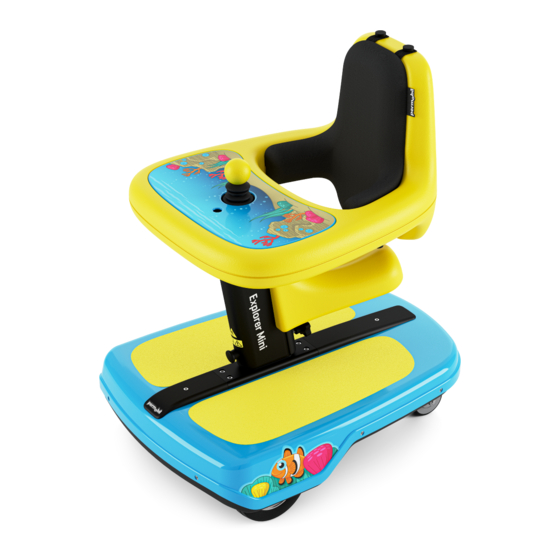
E. Caster wheel F. Drive wheel G. Joystick H. On/off button I. Table (part of the table and backrest unit) J. Column K. Base module L. Serial number M. Start button N. Main circuit breaker Figure 1. Explorer Mini overview. -
Page 13: Wiring Diagram
Explorer Mini Specifications - Wiring diagram Wiring diagram 3.2.1 Base module A. Battery saving module B. Drive unit, left C. nVR2 power module D. Contact to the left drive unit E. 24 V input F. Contact to the right drive unit G. -
Page 14: Serial Number Stickers
The serial number sticker is attached at the back of the nVR2 power module, facing the bottom of the base module. It is only visible when the nVR2 power module is removed from the Explorer Mini. Figure 6. Position of the serial number sticker on the nVR2 power module. -
Page 15: Repairs
Maintenance by a qualified service technician Only qualified service technicians should perform the maintenance and repair specified in this manual. Read all instructions carefully before proceeding. If any questions arise, contact Permobil for assistance. WARNING! Use supplied screws and recommended tightening... -
Page 16: Tray Top
Do not drive the wheelchair while the tray top is removed Do not let the child drive the Explorer Mini while the tray top is removed. The child may press the maximum speed buttons and affect the speed of the wheelchair by mistake. -
Page 17: Seat
Repairs - Seat Explorer Mini Seat 4.4.1 Removing the seat An adult or health-care provider must decide if seat removal is applicable for the child, taking into consideration his or her age and capacity. The center of gravity is affected when the seat is removed. -
Page 18: Installing The Seat
Repairs - Seat Explorer Mini 4.4.2 Installing the seat The center of gravity is affected when the seat is installed. The table and backrest unit must be in the highest position before you can install the seat. Otherwise there will not be enough space to install the seat. - Page 19 Repairs - Seat Explorer Mini 6. Release the plunger knob (A). A click signals that the plunger knob is locked. 7. Put back the tightening knob (B) and tighten it by hand. Figure 18. Release the plunger knob (A) and put back...
-
Page 20: Removing The Table And Backrest Unit
• Torque wrench. • Allen socket, 4 mm. • Screwdriver or pliers. 1. Put the Explorer Mini on a flat surface. 2. Press the on/off button (A) to turn off the power. 3. Turn off the main circuit breaker (B). - Page 21 Explorer Mini Repairs - Table and backrest unit 7. Remove the four screws and washers that attach the table to the bracket. Figure 22. Remove the four screws and washers. 8. Loosen the two screws from the key slots on the bracket. Do not remove the screws.
-
Page 22: Installing The Table And Backrest Unit
• Torque wrench. • Allen socket, 4 mm. • Screwdriver or pliers. 1. Put the Explorer Mini on a flat surface. 2. Press the on/off button (A) to turn off the power. 3. Turn off the main circuit breaker (B). - Page 23 Explorer Mini Repairs - Table and backrest unit 5. Put the table on the bracket with both screws fitted into the wide sections of the two key slots. Figure 27. Put the table on the bracket. 6. Carefully push the table forward on the bracket until the screws are locked in their positions.
- Page 24 Explorer Mini Repairs - Table and backrest unit 7. Attach the table to the bracket with the four screws and washers. Tightening torque: 3.5 lb. ft. WARNING! Use recommended tightening torque Use the recommended tightening torque to reduce the risk of damage to the wheelchair and to prevent causing injury to the user.
-
Page 25: Base Module
• Allen socket, 2.5 mm. • Allen socket, 4 mm. • Slotted screwdriver or pliers. 1. Put the Explorer Mini on a flat surface. 2. Press the on/off button (A) to turn off the power. 3. Turn off the main circuit breaker (B). - Page 26 Explorer Mini Repairs - Base module 5. Remove the screw from the cover on the UniTrack® at the front of the base module. Figure 36. Remove the screw from the cover on the UniTrack® at the front of the base module.
- Page 27 Explorer Mini Repairs - Base module 8. Remove the cable to the control panel from the UniTrack®. 9. Pull up the contact to the control panel through the hole of the top cover until you reach its contact and disconnect the cable.
- Page 28 Explorer Mini Repairs - Base module 13. Push back the cable to the nVR2 power module through the hole on the top cover. 14. Remove the six screws from the top cover. Figure 44. Positions of the six screws on the top cover.
- Page 29 Explorer Mini Repairs - Base module 4.6.1.2 Installing the top cover The following tools are necessary for this task: • Torque wrench. • Allen socket, 2.5 mm. • Allen socket, 4 mm. • Slotted screwdriver or pliers. 1. Put the top cover on the base module.
- Page 30 Explorer Mini Repairs - Base module 3. Attach the top cover on the base module with the six screws. Tightening torque: 0.9 lb. ft. WARNING! Use recommended tightening torque Use the recommended tightening torque to reduce the risk of damage to the wheelchair and to prevent causing injury to the user.
- Page 31 Explorer Mini Repairs - Base module 6. Put the two slide nuts into the grooves of the UniTrack® at the front of the base module and push the slide nuts until they reach the cover on the UniTrack® at the rear of the base module. If necessary, use a screwdriver to grip the holes in the slide nuts.
- Page 32 Explorer Mini Repairs - Base module 9. Make sure that the cable to the control panel is kept in the groove under the column assembly´s bracket and that it isn´t pinched. 10. Connect the cable from the control panel to the contact of the nVR2 power module.
-
Page 33: Bottom Cover
Explorer Mini Repairs - Base module 4.6.2 Bottom cover 4.6.2.1 Removing the bottom cover The following tools are necessary for this task: • Torque wrench. • Allen socket, 3 mm. • Allen socket, 4 mm. • Allen socket, 5 mm. - Page 34 Explorer Mini Repairs - Base module 5. Remove the four screws from the caster wheels assembly and remove the caster wheels assembly. Figure 60. Remove the caster wheels assembly. The bracket to the top cover, visible when the base module is in upright position, is also loosen.
- Page 35 Explorer Mini Repairs - Base module 8. Carefully lift the bottom cover and slide it off the metal chassis. Figure 64. Carefully lift the bottom cover and slide it off the metal chassis.
- Page 36 Explorer Mini Repairs - Base module 4.6.2.2 Installing the bottom cover The following tools are necessary for this task: • Torque wrench. • Allen socket, 3 mm. • Allen socket, 4 mm. • Allen socket, 5 mm. 1. Put the metal chassis upside down on a flat surface. Make sure that the cable from the nVR2 power module isn´t pinched by the metal...
- Page 37 Explorer Mini Repairs - Base module 3. Attach the bottom cover to the metal chassis with the six screws. Tightening torque: 2.1 lb. ft. WARNING! Use recommended tightening torque Use the recommended tightening torque to reduce the risk of damage to the wheelchair and to prevent causing injury to the user.
- Page 38 Explorer Mini Repairs - Base module 6. Attach the three screws and tighten all four screws to the caster wheels assembly. Tightening torque: 7.2 lb. ft. WARNING! Use recommended tightening torque Use the recommended tightening torque to reduce the risk of damage to the wheelchair and to prevent causing injury to the user.
- Page 39 Explorer Mini Repairs - Base module 10. Install the top cover. For instructions, see 4.6.1.2 Installing the top cover .
-
Page 40: Drive Wheels
Explorer Mini Repairs - Drive wheels Drive wheels 4.7.1 Removing the drive wheels The following tools are necessary for this task: • Torque wrench. • Allen socket, 5 mm. Each drive wheel is attached with three screws. Figure 74. Drive wheels. -
Page 41: Installing The Drive Wheels
Explorer Mini Repairs - Drive wheels 4.7.2 Installing the drive wheels The following tools are necessary for this task: • Torque wrench. • Allen socket, 5 mm. 1. For each drive wheel, put it onto the hub and attach it with the three screws. -
Page 42: Caster Wheels
5.1.2.1 Adjusting the height of the table and backrest unit . 4. Tilt the Explorer Mini 90° and put it on the floor with the caster wheels accessible. Figure 78. Tilt the Explorer Mini to access the caster wheels. -
Page 43: Installing The Caster Wheels
5.1.2.1 Adjusting the height of the table and backrest unit . 2. Tilt the Explorer Mini 90° and put it on the floor with the positions for the caster wheels accessible. Figure 80. Tilt theExplorer Mini to access the positions for the caster wheels. -
Page 44: Control Panel
Explorer Mini Repairs - Control panel Control panel 4.9.1 Removing the control panel The following tools are necessary for this task: • Torque wrench. • Allen socket, 3 mm. • Allen socket, 4 mm. • Allen socket, 5 mm. • Needle-nose pliers. - Page 45 Explorer Mini Repairs - Control panel 11. Remove the four screws and washers from the table bracket. Figure 84. Remove the table bracket. 12. Separate the table bracket from the column (approximately 10″) and pull out the cable pulley assembly from the column.
- Page 46 Explorer Mini Repairs - Control panel 16. Remove the cable to the control panel from the cable holder on the table bracket. Figure 88. Remove the cable to the control panel from the cable holder on the table bracket. 17. Remove the screws from the table bracket and remove the control panel from the table bracket.
-
Page 47: Installing The Control Panel
Explorer Mini Repairs - Control panel 4.9.2 Installing the control panel The following tools are necessary for this task: • Torque wrench. • Allen socket, 3 mm. • Allen socket, 4 mm. • Allen socket, 5 mm. • Needle-nose pliers. - Page 48 Explorer Mini Repairs - Control panel 5. Pull the end of the cable to the control panel through the cable pulley assembly. Figure 93. Pull the end of the cable to the control panel through the cable pulley assembly. 6. Pull the end of the cable to the control panel through the column.
- Page 49 Explorer Mini Repairs - Control panel 8. Put the cable pulley assembly (A) in the column and use a wire hook to pull the pull spring through the column. 9. Put the table bracket (B) on the top of the column. Make sure that the charger socket is facing the front of the column.
- Page 50 Explorer Mini Repairs - Control panel 11. Attach the table bracket on the top of the column with the four screws and washers. Tightening torque: 7.2 lb. ft. WARNING! Use recommended tightening torque Use the recommended tightening torque to reduce the risk of damage to the wheelchair and to prevent causing injury to the user.
-
Page 51: Batteries
4.10.1 Charging the batteries The Explorer Mini must only be charged with the supplied battery charger in a dry room with good ventilation. There is a green LED on the battery charger that is lit when the battery is fully charged. Read the user manual supplied with the battery charger. - Page 52 NOTICE Automatically locked for driving The Explorer Mini is automatically locked for driving during charging. If it is still possible to drive during charging, contact your dealer. 1. Press the on/off button to turn off the power.
-
Page 53: Removing The Batteries
Repairs - Batteries Explorer Mini 4.10.2 Removing the batteries • Torque wrench. • Allen socket, 3 mm. • Allen socket, 4 mm. • Allen socket, 5 mm. • Pliers. 1. Remove the top cover. For instructions, see 4.6.1.1 Removing the top cover . - Page 54 Repairs - Batteries Explorer Mini 4. Remove the two screws from the battery bracket, remove the battery bracket, including the battery saving module, and remove the batteries. Figure 104. Remove the battery bracket, including the battery saving module, and the batteries.
-
Page 55: Installing The Batteries
Repairs - Batteries Explorer Mini 4.10.3 Installing the batteries • Torque wrench. • Allen socket, 3 mm. • Allen socket, 4 mm. • Allen socket, 5 mm. • Pliers. 1. Put the batteries in the chassis with their terminals facing the caster wheels and attach the battery bracket, including the battery saving module, with the two screws. - Page 56 Repairs - Batteries Explorer Mini 4. Install the top cover. For instructions, see 4.6.1.2 Installing the top cover .
-
Page 57: Circuit Breakers
The main circuit breaker also functions as a fuse, and the Explorer Mini will automatically be turned off if an electrical fault occurs. If this happens you can try to turn on the Explorer Mini again. - Page 58 Explorer Mini Repairs - Circuit breakers 3. Remove the two screws from the cover of the main circuit breaker. Figure 109. Remove the cover from the main circuit breaker. 4. Press the snap-fit joint with a screwdriver or pliers, one side at a time, to remove the main circuit breaker from the bottom cover.
-
Page 59: Installing The Main Circuit Breaker
Explorer Mini Repairs - Circuit breakers 4.11.3 Installing the main circuit breaker • Torque wrench. • Torx T8 socket. • Pliers. 1. Snap the main circuit breaker in place to attach it in the hole of the bottom cover. Figure 111. Attach the main circuit breaker. - Page 60 Explorer Mini Repairs - Circuit breakers 4. Connect the two cables to the terminals of the main circuit breaker. Figure 114. Connect the main circuit breaker. 1. Install the top cover. For instructions, see 4.6.1.2 Installing the top cover .
-
Page 61: Removing The Start Button
Explorer Mini Repairs - Circuit breakers 4.11.4 Removing the start button • Torque wrench. • Torx T8 socket. • Pliers. 1. Remove the top cover. For instructions, see 4.6.1.1 Removing the top cover . 2. Disconnect the cable to the start button from the battery saving module. -
Page 62: Installing The Start Button
Explorer Mini Repairs - Circuit breakers 4.11.5 Installing the start button • Torque wrench. • Torx T8 socket. • Pliers. 1. Turn the start button with its connectors facing downward. 2. Pull the cable through the hole of the bottom cover and snap the start button in place. -
Page 63: Drive Unit
Repairs - Drive unit Explorer Mini 4.12 Drive unit 4.12.1 Removing the drive units The following tools are necessary for this task: • Torque wrench. • Allen socket, 3 mm. • Allen socket, 4 mm. 1. Remove the top cover. For instructions, see 4.6.1.1 Removing the top cover . - Page 64 Repairs - Drive unit Explorer Mini 7. Pull off the wheel hub from the axle to each drive unit. Figure 122. Pull off the wheel hub from the axle. 8. Remove the three screws from each drive unit and remove the drive units.
-
Page 65: Installing The Drive Units
Repairs - Drive unit Explorer Mini 4.12.2 Installing the drive units The following tools are necessary for this task: • Torque wrench. • Allen socket, 3 mm. • Allen socket, 4 mm. 1. Put each drive unit in the holes of the chassis. The axle of each drive... - Page 66 Repairs - Drive unit Explorer Mini 4. Connect the cable of each drive unit to the nVR2 power module. Make sure that the left and right output connector are connected to the left and right drive unit. Figure 127. Connect the drive units to the nVR2 power module.
-
Page 67: Nvr2 Power Module
Explorer Mini Repairs - nVR2 power module 4.13 nVR2 power module 4.13.1 Removing the nVR2 power module The following tools are necessary for this task: • Torque wrench. • Allen socket, 4 mm. 1. Remove the top cover. For instructions, see 4.6.1.1 Removing the top cover . -
Page 68: Installing The Nvr2 Power Module
Explorer Mini Repairs - nVR2 power module 4.13.2 Installing the nVR2 power module The following tools are necessary for this task: • Torque wrench. • Allen socket, 4 mm. 1. Attach the nVR2 power module to the metal chassis with the two screws. -
Page 69: Adjustments
WARNING! Do not adjust while the child is in the wheelchair Do not adjust the settings while the child is in the Explorer Mini. Seat 5.1.1 Adjusting the seat height The seat height is dependent on the height of the table and backrest unit. - Page 70 Figure 136. Loosen the tightening knob (A), hold the quickly and cause injury. table its position (B) and pull out the plunger knob (C). Make sure that the seat and the table and backrest unit are locked in their positions before the child sits in the Explorer Mini.
-
Page 71: Locking And Unlocking The Explorer Mini
5.2.1 Locking The Explorer Mini is unlocked with the steps below. Step 3 and 4 must be done swiftly, otherwise the procedure gets interrupted and you must start again from step 1. 1. Make sure that the Explorer Mini is turned on. -
Page 72: Unlocking
Adjustments - Locking and unlocking the Explorer Mini 5.2.2 Unlocking The Explorer Mini is unlocked with the steps below. Step 4 and 5 must be done swiftly, otherwise the procedure gets interrupted and you must start again from step 2. -
Page 73: Troubleshooting
Troubleshooting - Troubleshooting guide 6 Troubleshooting Troubleshooting guide This troubleshooting guide describes the most common events that can occur when you use the Explorer Mini. It also describes possible causes and remedies. This troubleshooting guide is not exhaustive. NOTICE Unapproved replacement of parts If any part is replaced without approval from Permobil, the wheelchair warranty will become void. - Page 74 Explorer Mini Troubleshooting - Troubleshooting guide Possible cause Remedy Event The main circuit breaker cannot be turned Electrical fault. For instructions on tripped main circuit breaker, see 4.11.1 Electrical fault .
-
Page 75: Control Panel Diagnostics
2. Turn on the wheelchair. If the fault continues, count the flashes and find a possible cause and remedy. See 6.2.4 Example of error messages and remedies . 3. Do not use the Explorer Mini until the problem is solved or you have received other information from your service provider. -
Page 76: Example Of Error Messages And Remedies
Troubleshooting - Control panel diagnostics 6.2.4 Example of error messages and remedies If the problem continues after you have done the remedies described in the table below, please contact your service provider or Permobil. For contact information, see 1.2 Technical support . Remedy Event... -
Page 77: Index
Explorer Mini Index Index Adjustments........69 Maximum speed indicator....75 Admonitions......... 10 nVR2 power module, install ..68 Base module, overview....25 nVR2 power module, remove ..67 Base module, wiring diagram ..13 nVR2 power module, serial Batteries, charging ......51 number ........ - Page 78 7 330818 360137...
Need help?
Do you have a question about the Explorer Mini and is the answer not in the manual?
Questions and answers