Table of Contents
Advertisement
Quick Links
Advertisement
Table of Contents
Troubleshooting

Related Manuals for Aerotech DR500

Summary of Contents for Aerotech DR500
- Page 1 Artisan Technology Group is your source for quality new and certified-used/pre-owned equipment SERVICE CENTER REPAIRS WE BUY USED EQUIPMENT • FAST SHIPPING AND DELIVERY Experienced engineers and technicians on staff Sell your excess, underutilized, and idle used equipment at our full-service, in-house repair center We also offer credit for buy-backs and trade-ins •...
- Page 2 RIVE HASSIS OPERATION & TECHNICAL MANUAL P/N: EDA120 (V1.6) AEROTECH, Inc. • 101 Zeta Drive • Pittsburgh, PA. 15238-2897 • USA Phone (412) 963-7470 • Fax (412) 963-7459 Product Service: (412) 967-6440; (412) 967-6870 (Fax) www.aerotech.com Artisan Technology Group - Quality Instrumentation ... Guaranteed | (888) 88-SOURCE | www.artisantg.com...
- Page 3 If you should have any questions about the DR500 and/or comments regarding the documentation, please refer to Aerotech online at: http://www.aerotech.com. For your convenience, a product registration form is available at our web site. Our web site is continually updated with new product information, free downloadable software, and special pricing on selected products.
-
Page 4: Table Of Contents
Bus #2, Unipolar ..........2-8 2.2.3.5. Bus #2, Bipolar........... 2-8 2.2.3.6. Bus Voltage Configuration......... 2-9 2.2.4. Installing A Drive Module in the DR500 ......2-10 2.2.5. Brush Drive Configuration (DS16020 or DS16030)..2-11 2.2.5.1. Electrical Specifications ........2-12 2.2.5.2. Fault Output............2-12 2.2.5.3. - Page 5 DAC Outputs Connector ............ 3-14 3.2.8. Motor Power Connector Pinouts ........3-15 3.2.9. DR500 Test Points ............. 3-16 3.3. DR500 Outline Drawings and Mechanical Specifications....3-17 3.4. Electrical Specifications ..............3-19 3.5. Environmental Specifications ............3-20 3.6. Emergency Stop Sense Input ............3-21 CHAPTER 4: SOFT-START / VOLTAGE SELECTOR BOARD ......
- Page 6 Power Supply Fusing 5V Adjust Potentiometer ....... 2-28 Figure 2-14. Drive Module Fuse Mounting ............2-29 Figure 2-15. DR500 Rear Panel Connector Layout ..........2-30 Figure 2-16. DR500 Electrical Connections ............2-31 Figure 2-17. U500/U600 Generic System Interconnect ........2-34 Figure 3-1.
- Page 7 List of Figures DR500 Operation and Technical Manual Aerotech, Inc. Version 1.6 Artisan Technology Group - Quality Instrumentation ... Guaranteed | (888) 88-SOURCE | www.artisantg.com...
- Page 8 Motor Connector (Brushless) ............3-15 Table 3-12. DR500 Rear Panel InterfaceTest Points ........... 3-16 Table 3-13. DR500 Drive InterfaceTest Points, Fuses, and L.E.D.s....3-16 Table 3-14. Weights for DR500 Packages (not including drives)......3-18 Table 3-15. Electrical Specifications ..............3-19 Table 4-1.
- Page 9 List of Tables DR500 Operation and Technical Manual Table 5-2. Power Checks ..................5-3 Table 5-3. Fuse Replacement Part Numbers ............5-4 Table 5-4. Preventative Maintenance..............5-5 Table R-1. Revisions ....................R-1 ∇ ∇ ∇ Aerotech, Inc. viii Version 1.6 Artisan Technology Group - Quality Instrumentation ... Guaranteed | (888) 88-SOURCE | www.artisantg.com...
- Page 10 The DR500 was tested with a CE-compliant, class B personal computer and it controlled four brushless AC motors. The DR500 requires a line filter (Aerotech P/N UFM) to meet conducted emission requirements. This filter may not be necessary if the DR500 is used by the OEM in a system that has a line filter.
- Page 11 Regulatory Information DR500 Operation and Technical Manual Aerotech, Inc. Version 1.6 Artisan Technology Group - Quality Instrumentation ... Guaranteed | (888) 88-SOURCE | www.artisantg.com...
-
Page 12: Chapter 1: Introduction
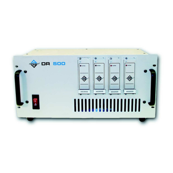
The individual amplifiers (a maximum of four) are inserted into the front of the DR500 panel. The back of the DR500 has all the cable connectors as well as descriptions for each. The DR500 Drive Chassis is shown in Figure 1-1. -
Page 13: Dr500 Functions
• Assure a fail-safe connection to the U500/U600 controller. 1.1.2. DR500 Configurations The DR500 is easily configured to the users needs and can be set up for a wide range of applications. It can be configured to: • House up to 4 DC servo, AC brushless, or microstepping amplifiers •... -
Page 14: Dr500 Options
UNIDEX 500 / UNIDEX 600 System Diagram 1.2. DR500 Options A variety of options may be purchased with the DR500 drive chassis to enhance its standard operation. The following sections discuss the available options. 1.2.1. The SHUNT500 Regulator Board The SHUNT500 regulator board provides shunt regulated bus voltage. Figure 1-3 shows the interconnections of the SHUNT500 regulator board. -
Page 15: Figure 1-3. Shunt500 Wiring
Figure 1-3. SHUNT500 Wiring The SHUNT500 board, shown in Figure 1-5, is an integral option to the DR500 used to regulate either one or both of the bus power supplies (both, if supplies are connected together). Typically, the SHUNT500 board is required for motors operating from a 160 VDC bus with large inertial loads, which, on deceleration, return the energy back into the power supply, potentially damaging the drive module. -
Page 16: Drc I/O Cable
WARNING 1.2.2. DRC I/O Cable The DRC I/O cable serves two purposes when used with the DR500 Drive Chassis. The primary use is for applications that use brushless motors with Hall effect sensors. In such cases, the necessary Hall effect signals are not available through the standard OP500 cable, therefore, the DRC cable is connected between the U600/U500 and the DR500. -
Page 17: Figure 1-6. Drc I/O Cable
Introduction DR500 Operation and Technical Manual Shielded Ribbon Cable 3M PN. 3659-50 UNIDEX 500-P5 DR300 Connect shield wire to pin 50 this end only (Red UNIDEX 600-P10 line is #1) then cover with heatshrink 2 pls. AMP PN. 3425-6050 Qty. 2 Approx. -
Page 18: Dr500 Brake Option
DR500 Operation and Technical Manual Introduction 1.2.3. DR500 Brake Option The DR500 brake option, shown in Figure 1-8, is an integral option that provides a fail-safe way to maintain position on a vertical axis when power is removed from that Vertical axis. -
Page 19: Safety Procedures And Warnings
Introduction DR500 Operation and Technical Manual 1.3. Safety Procedures and Warnings The following statements apply wherever the Warning or Danger symbol appears within this manual. Failure to observe these precautions could result in serious injury to those performing the procedures and/or damage to the equipment. - Page 20 WARNING Remove the packing list from the DR500 container. Make sure that the items specified on the packing list are contained within the package. Certain items required for use with your DR500 are not included within the DR500 shipping container. These items may be found in the UNIDEX 500/600 shipping container.
-
Page 21: Chapter 2: Set Up
The DR500 is configured by the factory according to the specifications given by the user. The user should not need to reconfigure the DR500 chassis. However, if there is a need to add change the type of amplifier for an axis, it will be necessary to configure the slot jumpers, shown in Figure 2-1 and Figure 2-2, according to the following sections. -
Page 22: Rear Panel Interface Board Internal Jumpers
DR500 Operation and Technical Manual Set Up 2.2.1. Rear Panel Interface Board Internal Jumpers This section covers the configurations of the slot jumpers on the DR500 Rear Panel Interface board. Table 2-1 lists the configurations and jumper selections for the Rear Panel Interface board. - Page 23 Set Up DR500 Operation and Technical Manual BW55 BW5 F.S. 9000UF 100V 9000UF 100V F7 RXE250 BW54 BW16 BW15 BW12 M2 F.S. 74AC12 HCPL3700 S.B. F.S. BW26 3.15A S.B. BW25 74AC14 74AC05 74AC05 BW36 JP16 JP26 JP36 BW35 JP46 PAD 1...
-
Page 24: Table 2-2. Drive Interface Board Jumper Selections
DR500 Operation and Technical Manual Set Up Table 2-2. Drive Interface Board Jumper Selections Configuration Jumpers Standard Optional ESTOP disables drives Yes: Axis 1 Remove JP16 Install JP16 Axis 2 Remove JP26 Install JP26 Axis 3 Remove JP36 Install JP36... - Page 25 Set Up DR500 Operation and Technical Manual Table 2-2. Drive Interface Board Jumper Selections (Continued) Configuration Jumpers Standard Optional Unipolar (0-X, 40-X, 80-X, 160-X) Install: BW4, BW6, BW54, BW55 Bipolar (30-X) Remove: BW5 Install: (EIK00226 – QUICK Bus Power Supply #1 Unipolar (160LT-X) CONN.
-
Page 26: Table 2-3. Drive Interface Bd. Jumper Selections For Am16007 Stepper Drive
DR500 Operation and Technical Manual Set Up Table 2-3. Drive Interface Bd. Jumper Selections for AM16007 Stepper Drive AXIS FUNCTION AM16007 STEPPING DRIVE CONFIGURATION MTR OUTPUT BW15, 16 OUT BW25, 26 OUT BW35, 36 OUT BW45, 46 OUT PHASE D/B-... -
Page 27: Bus Configuration
BW43 IN 2.2.3. Bus Configuration The DR500 provides two different bus voltages with each capable of being set as a unipolar or bipolar power supply. Each bus power supply may be 40, 80, or 160 VDC unipolar (single supply) or as a 30 VDC bipolar supply (dual (+) and (–) supply). The 30 VDC bipolar power supply is for use with the linear three-phase AC brushless drive (AS3005). -
Page 28: Bus Voltage Configuration
BW5 and the Bus supply #2 transformer centertap connection is BW8. These transformers are mounted internally on the left side of the DR500 with T1 used for bus supply #1 and T2 used for bus supply #2. When Autotransformers and offline methods are used to provide power to the bus supplies the bus supply cannot be grounded. -
Page 29: Installing A Drive Module In The Dr500
WARNING Before installing a drive module into a slot in the DR500 (refer to Figure 2-3), it is necessary to configure the jumpers on the Drive Interface board for that type of drive module. -
Page 30: Brush Drive Configuration (Ds16020 Or Ds16030)
DR500 Operation and Technical Manual Set Up 2.2.5. Brush Drive Configuration (DS16020 or DS16030) To configure a slot in the DR500 for a brush drive module (refer to Figure 2-4 for DS16020 and DS16030), proceed with the following steps: •... -
Page 31: Electrical Specifications
Set Up DR500 Operation and Technical Manual 2.2.5.1. Electrical Specifications Electrical specifications are listed in Table 2-7. Table 2-7. DS160 Series Electrical Specifications Units DS16020 DS16030 Peak Current Output (2 sec) Amps ±20 ±30 ±10 ±15 Continuous Output Current Amps (±... -
Page 32: Personality Module
DR500 Operation and Technical Manual Set Up 2.2.5.3. Personality Module The Personality Module pre-amplifier circuit, RCN4, (shown in Figure 2-6) is used to interface input and tach feedback signals (if any exist). Figure 2-3 shows the location of this module. -
Page 33: Figure 2-5. Simplified Block Diagram Of The Ds160 Series Servo
Set Up DR500 Operation and Technical Manual Figure 2-5. Simplified Block Diagram of the DS160 Series Servo Amplifier Module Aerotech, Inc. 2-14 Version 16 Artisan Technology Group - Quality Instrumentation ... Guaranteed | (888) 88-SOURCE | www.artisantg.com... -
Page 34: Figure 2-6. Ds16020 / Ds16030 Brush Drive Modules Pre-Amp Schematic
DR500 Operation and Technical Manual Set Up 10K 1 TURN SELECT 0 OHM RCN4-C Figure 2-6. DS16020 / DS16030 Brush Drive Modules Pre-Amp Schematic Aerotech, Inc. Version 1.6 2-15 Artisan Technology Group - Quality Instrumentation ... Guaranteed | (888) 88-SOURCE | www.artisantg.com... -
Page 35: Setting The Current Limit
Set Up DR500 Operation and Technical Manual 2.2.5.4. Setting the Current Limit The RCN4 resistor component 8-9 is used to set the maximum current that can be obtained by the current limit potentiometer (full CW for zero current, full CCW for maximum current). - Page 36 DR500 Operation and Technical Manual Set Up Input Pot Full CCW Input Pot Full CW Gain (dB) Gain Pot Center Gain Pot Full CW Transfer Function Icom Vcom 1000 10000 100000 Frequency (Hz) Tach Pot Full CCW Gain Tach Pot Full CW...
-
Page 37: Figure 2-8. Outline Of Personality Module Rcn4
Set Up DR500 Operation and Technical Manual 16 Pin DIP Wafer (snap-on cover removed) RCN4 1-16 (Resistor, ¼ Watt) RCN4 2-15 (Resistor, ¼ Watt) RCN4 3-14 (Resistor, ¼ Watt) RCN4 4-13 (Resistor, ¼ Watt) RCN4 5-12 (Ceramic Capacitor, 50V) RCN4 6-11 (Resistor, ¼ Watt) RCN4 7-10 (Resistor, ¼... -
Page 38: Figure 2-9. Detailed Electrical Diagram Of Ds160 Post-Amplifier Circuit
DR500 Operation and Technical Manual Set Up Figure 2-9. Detailed Electrical Diagram of DS160 Post-Amplifier Circuit Aerotech, Inc. Version 1.6 2-19 Artisan Technology Group - Quality Instrumentation ... Guaranteed | (888) 88-SOURCE | www.artisantg.com... -
Page 39: Troubleshooting The Ds160 Series
Set Up DR500 Operation and Technical Manual 2.2.5.7. Troubleshooting the DS160 Series A troubleshooting guide for the DS160 Series Servo Amplifier module is provided in Table 2-12. A list of recommended spare parts for the DS160 Series Servo Amplifier Module is shown in Table 2-13. -
Page 40: Table 2-12. Ds160 Series Troubleshooting Guide
DR500 Operation and Technical Manual Set Up Table 2-12. DS160 Series Troubleshooting Guide Condition Possible Cause References Shutdown input (pin 6, J1) is pulled low. See Figure 2-5. Active LED is de-energized, High DC bus voltage (pins 28, 32 or J1). -
Page 41: Stepper Drive Configuration (Am16007)
Set Up DR500 Operation and Technical Manual 2.2.6. Stepper Drive Configuration (AM16007) To configure a slot in the DR500 for a stepper drive module (Figure 2-10), proceed with the following steps: • Set jumpers and drive key according to AM16007 Stepper Drive Configuration Table 2-3. - Page 42 DR500 Operation and Technical Manual Set Up Table 2-14. AM16007 Series Electrical Specifications Units AM16007 Peak Current Output (2 sec) Amps ±7.5 Continuous Output Current Amps ±5 Output Fuse, F1 (10 ASB) Amps Peak Output Voltage Volts Power Amplifier Gain (continuous output)
-
Page 43: Ac Brushless Drive Configuration (As32020 Or As32030)
Set Up DR500 Operation and Technical Manual 2.2.7. AC Brushless Drive Configuration (AS32020 or AS32030) To configure a slot in the DR500 for an AC brushless drive module (Figure 2-11), proceed with the following steps: • Set jumpers and drive key according to AS32020 / AS32030 Brush Drive Configuration Table 2-5. - Page 44 DR500 Operation and Technical Manual Set Up Table 2-16. AS32020 / AS32030 Series Electrical Specifications Units AS32020 AS32030 Peak Current Output (2 sec) Amps ±20 ±30 Continuous Output Current Amps ±7 ±10.7 Output Fuse, F1 (3 AG, slow blow) Amps...
-
Page 45: Ac Brushless Linear Drive Configuration (As3005)
Set Up DR500 Operation and Technical Manual 2.2.8. AC Brushless Linear Drive Configuration (AS3005) To configure a slot in the DR500 for an AC brushless linear drive module (Figure 2-12), proceed with the following steps: • Set jumpers and drive key according to AS3005 Brushless Drive Configuration Table 2-6. -
Page 46: Internal System Wiring
Phase C Offset Adjust 2.2.9. Internal System Wiring The DR500 wiring varies depending upon the desired AC input voltage, the number of axes, and the desired DC bus voltage required for the drive modules. A system wiring drawing is provided with the documentation package for all DR500 systems. -
Page 47: Power Supply Fusing
Aside from the two Bus power supplies, the DR500 contains a power supply that provides +5, +12, -12, and +24 VDC. This supply is located on the left side of the DR500 and is not user serviceable. Several re-settable fuses are located on the interface board for external +5V usage. -
Page 48: Motor Fusing
Loosen the two screws on the cover plate of the drive module securing it to the front of the chassis, refer to Figure 2-14 • Remove the drive module from the DR500, refer to Figure 2-14 • Check for proper fuse size and type, and replace the fuse on the drive module. -
Page 49: External Device Power
2.6. Mechanical Installation The DR500 Rack Mount package is designed to be mounted into a standard 19” rack. The Desktop package can be placed on desk or bench top. Allowance must be made for the rear panel connections and cables. -
Page 50: Electrical Installation
When using an AC brushless motor or the I/O bus, use the optional DIOSR/DRC cable that connects to P5 of the U500 or P10 of the U600 and to the rear of the DR500 to connector J10 (labeled “From UNIDEX 500-P5/U600-P10”). This cable accommodates Hall effect feedback devices. -
Page 51: Dr500 Power Up
DR500 Operation and Technical Manual 2.7.1. DR500 Power Up To safely power up the DR500, properly connect all drive modules and cables to the DR500 before turning on the chassis. Likewise, always turn the system off before removing any cables from the DR500 chassis. Locate the system serial label in the upper left corner of the DR500 rear panel. -
Page 52: Dr500 Interface
2.8. DR500 Interface The UNIDEX 500/600 is connected to the DR500 drive rack by connecting one or two optional cables between the units. The OP500 cable, a 100 conductor shielded cable, carries all control signals. This cable connects from P1 on the UNIDEX 500/600 motion processor board installed in the personal computer to the connector at the back of the DR500 Drive Chassis labeled "From UNIDEX 500/600 P1". -
Page 53: Figure 2-17. U500/U600 Generic System Interconnect
Set Up DR500 Operation and Technical Manual Figure 2-17. U500/U600 Generic System Interconnect ∇ ∇ ∇ Aerotech, Inc. 2-34 Version 16 Artisan Technology Group - Quality Instrumentation ... Guaranteed | (888) 88-SOURCE | www.artisantg.com... -
Page 54: Chapter 3: Technical Details
All input and output designations are relative to the UNIDEX 500/600 CPU board, connector P1. All connectors are N.C. (no connection) where blank. Refer to Figure 3-1 for the location of the connectors on the rear of the DR500 Chassis assembly. -
Page 55: Table 3-1. Pinouts For Connector J1 (Interface To U500/U600 Connector P1)
Technical Details DR500 Operation and Technical Manual Table 3-1. Pinouts for Connector J1 (Interface to U500/U600 Connector P1) Pin # Description Pin # Description Interlock Send Common Sync (unused) / Common Hall Effect HC1 U500/U600 +5 Volts +12 VDC OUT / DAC +12 VDC IN *... -
Page 56: Pin Descriptions
For hardware specific information on a signal, refer to your controller’s hardware manual. Pin 1 - Interlock Send The DR500 input is a logic signal driven by the UNIDEX 500/600 to sense the presence of the DR500 Drive Chassis. UNIDEX 500/U600 drives this line and senses... -
Page 57: Figure 3-2. Cw Motor Rotation Viewed From Mounting Flange End
Technical Details DR500 Operation and Technical Manual COS-N SIN-N MKR-N Figure 3-2. CW Motor Rotation Viewed from Mounting Flange End FORCER WIRES + MOVE (Clockwise) FORCER MAGNET TRACK Figure 3-3. Linear Motor (Forcer) CW Direction Aerotech, Inc. Version 1.6 Artisan Technology Group - Quality Instrumentation ... Guaranteed | (888) 88-SOURCE | www.artisantg.com... - Page 58 DR500 Operation and Technical Manual Technical Details PINOUTS INCLUDE Pin 5 – HB1 This is axis #1 hall Effect Sensor B output Pin 6 – HA1 This is axis #1 Hall Effect Sensor A output Pin 7 - Sine This is the active high sine output from a differential quadrature type square wave encoder used for position and/or velocity feedback.
- Page 59 Technical Details DR500 Operation and Technical Manual Each of the following end of travel limit switch inputs (39-50) are contact closure signals. See the UNIDEX 500/U600 manuals for additional information concerning the end of travel limits. Pin 39 - CW Limit Axis 1 When activated, this signal immediately stops all clockwise motion of the motor.
- Page 60 The following four signals are the same user inputs (to the U500/U600 board) that are available on the I/O bus connector (J11) on the rear of the DR500 chassis. See the U500/600 manuals for additional information concerning the user inputs.
- Page 61 Technical Details DR500 Operation and Technical Manual The following four input signals from the U500/U600 board are +5 volt logic level signals used to enable the drive modules. There is a pull up resistor (10K ohm typical) on each of these inputs. These inputs require the logic level to be low to engable the drive module in a standard configuration.
- Page 62 Refer to the description preceding pin 97. Pin 100 - Interlock Receive Output This output is connected to pin 1 and is monitored by the U500/U600 controller to verify proper connection of the DR500. The U500/U600 manuals provide additional information concerning this signal. Aerotech, Inc.
-
Page 63: Dr500 Rear Panel Connectors
DR500 Operation and Technical Manual 3.2. DR500 Rear Panel Connectors There are 14 connectors on the rear panel of the DR500 Chassis. The following sections show the pinouts for each connector and a description for each pin in the connector. 3.2.1. Motor Axis Connectors Table 3-2 shows the pinouts for Axis 1 through Axis 4. -
Page 64: Pin
DR500 Operation and Technical Manual Technical Details 3.2.2. Joystick Connector Table 3-3 shows the pinouts for the Joystick connector. The mating connector is a Cinch # DA-15P (Aerotech # ECK100). Table 3-3. Pinouts for the Joystick Interface Connector (J12) Pin #... -
Page 65: Miscellaneous Input/Output Connector
3.2.4. Brake Connector Table 3-5 shows the pinouts for the brake connector. The mate to this connector is a Cinch # DA-15P (Aerotech # ECK100). The optional fail-safe brake may also be driven by the J2-J5 connectors (see Section 2.2.1). -
Page 66: Digital I/O Connector
Table 3-6 shows the pinouts for the digital I/O or "From U500 P-5/U600 P10" connector. The mate to this connector is a 3M #3425-6050 (Aerotech # ECK332). This connector is normally used to connect to U500-P5 or U600-P10. This is required if Hall effect sensors (brushless only) are used as shown in section 1.2.2. -
Page 67: The Opto-22 Connector
3.2.6. The Opto-22 Connector Table 3-7 shows the pinouts for the Input/Output (I/O) or Opto-22 Bus connector. The mating connector is a 3M #3564-1001 (Aerotech # ECK353). This connector is normally used to connect to U500-P5 or U600-P10 if Hall effect sensors are used. -
Page 68: Motor Power Connector Pinouts
3.2.8. Motor Power Connector Pinouts The motor power connector is a 14 pin AMP circular plastic motor connector. The mating connector is an AMP #206044-1 (Aerotech # ECK131). The backshell is an AMP #206070-1 (Aerotech # ECK134). The pins for the connector are AMP #66098-7 (Aerotech # EIK194). -
Page 69: Dr500 Test Points
Technical Details DR500 Operation and Technical Manual 3.2.9. DR500 Test Points Table 3-12 describes the DR500 Rear Panel Interface board test points. Table 3-13 describes the DR500 Drive Interface board test points, fuses, and L.E.Ds. Table 3-12. DR500 Rear Panel InterfaceTest Points... -
Page 70: Dr500 Outline Drawings And Mechanical Specifications
3.3. DR500 Outline Drawings and Mechanical Specifications The DR500 Desktop package includes rubber standoffs or supports. Refer to Figure 3-5 for dimensions. The rack mount package contains the same chassis as the Desktop package with a slightly wider front panel that includes handles and mounting flanges (see Figure 3-6). -
Page 71: Figure 3-6. Dr500 Rack Mount Package
DIMENSIONS: Millimeters [Inches] Figure 3-6. DR500 Rack Mount Package The weights for each package are provided in Table 3-14. Table 3-14. Weights for DR500 Packages (not including drives) # of 40, 60, or 80V 40, 60, or 80, and VAC IN... -
Page 72: Electrical Specifications
115 VAC, 230 VAC, 100 VAC, and 208 VAC (refer to Table 3-15). Each DR500 systems power specifications can be found on the power specification tag located on the rear of the DR500 chassis (see following example). -
Page 73: Environmental Specifications
Technical Details DR500 Operation and Technical Manual 3.5. Environmental Specifications • Ambient Temperature: Operating: 5° - 40°C (41° - 104°F) Storage: -20 - 70°C (-4 - 158°F) • Maximum relative humidity is 80% for temperatures up Humidity: to 31°C. Decreasing linearly to 50% relative humidity at 40°C. -
Page 74: Emergency Stop Sense Input
DR500 Operation and Technical Manual Technical Details 3.6. Emergency Stop Sense Input The UNIDEX 500/U600 has an optically isolated emergency stop sense input. See your controller’s hardware manual for more information. The U500 and U600 require a parameter change before it will recognize the ESTOP circuit. - Page 75 Technical Details DR500 Operation and Technical Manual Aerotech, Inc. 3-22 Version 1.6 Artisan Technology Group - Quality Instrumentation ... Guaranteed | (888) 88-SOURCE | www.artisantg.com...
-
Page 76: Chapter 4: Soft-Start / Voltage Selector Board
DR500 Operation and Technical Manual Soft-Start CHAPTER 4: SOFT-START / VOLTAGE SELECTOR BOARD In This Section: • Soft-Start / Voltage Selector Overview ....4-1 • Soft-Start Operation..........4-2 • Voltage Selector Function ........4-3 • Connector Pinouts ..........4-4 • Fuse Information............. 4-6 4.1. -
Page 77: Soft-Start Operation
Soft-Start DR500 Operation and Technical Manual 4.2. Soft-Start Operation Soft-start operation is an automatic function that limits inrush current to approximately 10 amps for 100/115 VAC operation and 20 amps for 200/230 VAC operation. Inrush current limiting is only activated during initial power-up or when AC power interruptions last longer than .3 seconds. -
Page 78: Voltage Selector Function
DR500 Operation and Technical Manual Soft-Start 4.3. Voltage Selector Function The Soft-Start / Voltage Select Board contains four user settable switches (S1-S4) to configure the controller for 100 VAC, 115 VAC, 200 VAC or 230 VAC input power. The voltage selector can only be used with transformers designed to interface with this board. -
Page 79: Connector Pinouts
Transformer Thermal Switch Transformer 115VAC Lead (WHT WIRE) (BLK WIRE) NOTE: Transformer colors are referenced to custom Aerotech transformers only (P.N. EAX01010). Do not use with other transformers. Aerotech, Inc. Version 1.6 Artisan Technology Group - Quality Instrumentation ... Guaranteed | (888) 88-SOURCE | www.artisantg.com... -
Page 80: Fan Interface Connector (J4)
DR500 Operation and Technical Manual Soft-Start 4.4.4. Fan Interface Connector (J4) The pinouts for the Fan Interface connector are listed in Table 4-5. Table 4-5. Fan Interface Connector (J4) Pinouts Description Fan AC HI (115VAC) FAN AC LO The Fan Interface Connector is for AC fans (115 VAC typical) only. Do Not Use With DC Fans. -
Page 81: Fuse Information
Soft-Start DR500 Operation and Technical Manual 4.5. Fuse Information The Soft-Start / Voltage Select Board contains four fuses (F1-4) used in the Voltage Select circuit to protect the transformers. Fuses F1 and F3 (Typical value: 4 Amps) provide the primary protection for 100 and 115 VAC operation. Fuses F2 and F4 (Typical value: 3 Amps) provide the primary protection for 200 and 230 VAC operation. -
Page 82: Chapter 5: Troubleshooting
DR500 Operation and Technical Manual Troubleshooting CHAPTER 5: TROUBLESHOOTING In This Section: • Warning and Cautions ......... 5-1 • Amplifier Related Problems ......5-2 • Power Related Problems......5-3 • Fuse Replacement........5-4 • Preventative Maintenance......5-5 • Cleaning............5-6 5.1. -
Page 83: Amplifier Related Problems
Check Encoder and Hall feedback. Check parameters. Motor runs away Check Encoder and Hall feedback phasing. Always disconnect main power connection before opening the DR500 chassis. WARNING Aerotech, Inc. Version 1.6 Artisan Technology Group - Quality Instrumentation ... Guaranteed | (888) 88-SOURCE | www.artisantg.com... -
Page 84: Power Related Problems
DR500 Operation and Technical Manual Troubleshooting 5.3. Power Related Problems The DR500 contains several power supplies that generate +5V, +12V, -12V, and the bus supplies. Table 5-2 lists some power checks that can be made. Table 5-2. Power Checks Symptom Possible Causes Verify power switch is on. -
Page 85: Fuse Replacement
Troubleshooting DR500 Operation and Technical Manual 5.4. Fuse Replacement Table 5-3 lists the manufacturer and Aerotech’s part number for typical replacement fuses. Additional fuse information can be found on the system drawing supplied with the unit. Table 5-3. Fuse Replacement Part Numbers... -
Page 86: Preventative Maintenance
5.5. Preventative Maintenance The DR500 and external wiring should be inspected monthly. Inspections may be required at more frequent intervals, depending on the environment and use of the system. Table 5-4 lists the recommended checks that should be made during these inspections. -
Page 87: Cleaning
5.6. Cleaning The DR500 should be wiped with a clean, dry (or slightly damp with water), soft cloth. Fluids and sprays are not recommended because internal contamination may result in electrical shorts and/or corrosion. The electrical power must be disconnected from the DR500 while cleaning. -
Page 88: Appendix A: Warranty And Field Service
Aerotech makes no warranty that its products are fit for the use or purpose to which they may be put by the buyer, whether or not such use or purpose has been disclosed to Aerotech in specifications or drawings previously or subsequently provided, or whether or not Aerotech’s products are specifically designed and/or manufactured for... - Page 89 DR500 Operation and Technical Manual Returned Product Non- After Aerotech’s examination, the buyer shall be notified of the repair cost. At such time warranty Determination the buyer must issue a valid purchase order to cover the cost of the repair and freight, or authorize the product(s) to be shipped back as is, at the buyer’s expense.
- Page 90 DR500 Operation and Technical Manual Index INDEX Symbols +12V Input Pinout, 3-6, 3-7 Brush Motor Drive Modules, 2-10 5 Volt Logic Inputs, 3-8 Brushless Motor, 2-33 50 Conductor Ribbon Cable, 2-33 Bus Power Supply Fuse Location, 2-28 Bus Voltage, 1-3, 2-8...
- Page 91 Index DR500 Operation and Technical Manual Joystick, 3-11 Personality module, 2-13 Miscellaneous I/O, 3-12 Post-amplifier specifications, 2-16, 2-19 Motor Power, 3-15 Power stage specifications, 2-20 P1, 2-33 Pre-amplifier P10, 2-33 Specifications, 2-12 P5, 2-33 Spare parts, 2-21 Contact Closure Inputs, 3-6...
- Page 92 Installation Mode Control Axis 2 Output, 3-7 Drive Modules, 2-10 Mode Control Axis 3 Output, 3-7 Mode Control Axis 4 Output, 3-7 Installing A Drive Module In The DR500, 2-10 Interface Mode Selection Drive Rack, 2-33 Joystick, 3-9 Interface Board, 2-3, 2-30...
- Page 93 Index DR500 Operation and Technical Manual Axis Enable 4 Output, 3-8 Providing Power to Encoder, 3-3 Axis Fault 1 Input, 3-8 PWM Current Regulators, 3-3 Axis Fault 4 Input, 3-8 Brake Connector, 3-12 Brake Output, 3-9 CCW Limit Axis 1, 3-6...
- Page 94 DR500 Operation and Technical Manual Index DS160 series, 2-20, 2-21 Voltage Selector Board Turning On Chassis, 2-32 Function, 4-3 User Settable Switches (S1 – S4), 4-3 Warnings, 4-3 Unpacking the DR500, 2-1 User Input 1 Pinout, 3-7 User Input 2 Pinout, 3-7...
- Page 95 Index DR500 Operation and Technical Manual Aerotech, Inc. Version 1.6 Artisan Technology Group - Quality Instrumentation ... Guaranteed | (888) 88-SOURCE | www.artisantg.com...
- Page 96 DR500 Operation and Technical Manual Revision History REVISION HISTORY In This Section: • Revisions ........... R-1 Revisions The following section provides the user with general information regarding the latest changes to this manual. Extensive changes, if made, may not be itemized – instead, the section or chapter will be listed with “extensive changes”...
- Page 97 Revision History DR300 Operation and Technical Manual Aerotech, Inc. Version 1.6 Artisan Technology Group - Quality Instrumentation ... Guaranteed | (888) 88-SOURCE | www.artisantg.com...
- Page 98 READER’S COMMENTS AEROTECH DR500 Drive Chassis P/N EDA 120, May 2002 Please answer the questions below and add any suggestions for improving this document. Is the information: Adequate to the subject? ____ ____ Well organized? ____ ____ Clearly presented? ____...
- Page 99 Artisan Technology Group - Quality Instrumentation ... Guaranteed | (888) 88-SOURCE | www.artisantg.com...
- Page 100 Artisan Technology Group is your source for quality new and certified-used/pre-owned equipment SERVICE CENTER REPAIRS WE BUY USED EQUIPMENT • FAST SHIPPING AND DELIVERY Experienced engineers and technicians on staff Sell your excess, underutilized, and idle used equipment at our full-service, in-house repair center We also offer credit for buy-backs and trade-ins •...
Need help?
Do you have a question about the DR500 and is the answer not in the manual?
Questions and answers