
Related Manuals for Nexcom NISE 105U


Summary of Contents for Nexcom NISE 105U
- Page 1 NEXCOM International Co., Ltd. IoT Automation Solutions Business Group Fan-less Computer NISE 105U/105U User Manual NEXCOM International Co., Ltd. www.nexcom.com Published June 2019...
-
Page 2: Table Of Contents
DVI-I Connector ................17 Knowing Your NISE 105U ...............4 COM2 Port ..................18 Front Panel ..................4 COM3 Port ..................18 Rear Panel ...................5 COM4 Port ..................19 Mechanical Dimensions ................6 Copyright © 2019 NEXCOM International Co., Ltd. All Rights Reserved. NISE 105U User Manual... - Page 3 Installing a SIM Card ................38 Installing a SATA Storage Drive ..............40 Wall Mounting Instructions ..............42 Chapter 4: BIOS Setup About BIOS Setup .................43 When to Configure the BIOS ..............43 Copyright © 2019 NEXCOM International Co., Ltd. All Rights Reserved. NISE 105U User Manual...
-
Page 4: Preface
No describes how to keep the system CE compliant. part of this manual may be reproduced, copied, translated or transmitted in any form or by any means without the prior written consent from NEXCOM Declaration of Conformity International Co., Ltd. -
Page 5: Rohs Compliance
(Cr6+) < 0.1% or 1,000ppm, Polybrominated biphenyls (PBB) < 0.1% or 1,000ppm, and Polybrominated diphenyl Ethers (PBDE) < 0.1% or 1,000ppm. In order to meet the RoHS compliant directives, NEXCOM has established an engineering and manufacturing task force to implement the introduction of green products. -
Page 6: Warranty And Rma
(manuals, cable, etc.) and any components from the card, such as CPU and RAM. If the components were suspected as part of the problems, ▪ If RMA goods can not be repaired, NEXCOM will return it to the customer please note clearly which components are included. Otherwise, NEXCOM without any charge. - Page 7 ESD workstation. If no such station is available, you can provide some ESD protection by wearing an antistatic wrist strap and attaching it to a metal part of the computer chassis. Copyright © 2019 NEXCOM International Co., Ltd. All Rights Reserved. NISE 105U User Manual...
-
Page 8: Safety Information
▪ Avoid using the system near water, in direct sunlight, or near a heating device. There must be a disconnect device in front of “NISE 105U”to keep the worker or field side maintainer be cautious and aware to close the general ▪... -
Page 9: Installation Recommendations
Using your fingers can disconnect most of the connections. It is recommended that you do not use needle-nose pliers to disconnect connections as these can damage the soft metal or plastic parts of the connectors. Copyright © 2019 NEXCOM International Co., Ltd. All Rights Reserved. NISE 105U User Manual... -
Page 10: Safety Precautions
REPLACED. REPLACE ONLY WITH THE SAME OR EQUIVALENT TYPE 10. All cautions and warnings on the equipment should be noted. RECOMMENDED BY THE MANUFACTURER. DISCARD USED BATTERIES ACCORDING TO THE MANUFACTURER’S INSTRUCTIONS. Copyright © 2019 NEXCOM International Co., Ltd. All Rights Reserved. NISE 105U User Manual... -
Page 11: Technical Support And Assistance
Preface Technical Support and Assistance Conventions Used in this Manual 1. For the most updated information of NEXCOM products, visit NEXCOM’s Warning: website at www.nexcom.com. Information about certain situations, which if not observed, can cause personal injury. This will prevent injury to yourself 2. -
Page 12: Global Service Contact Information
16F, No.250, Sec. 2, Chongde Rd., Beijing, 100094, China Beitun Dist., Tel: +86-10-5704-2680 Taichung City 406, R.O.C. Fax: +86-10-5704-2681 Tel: +886-4-2249-1179 Email: sales@nexcom.cn Fax: +886-4-2249-1172 www.nexcom.cn Email: sales@nexcom.com.tw www.nexcom.com.tw Copyright © 2019 NEXCOM International Co., Ltd. All Rights Reserved. NISE 105U User Manual... - Page 13 Tokyo, 108-0014, Japan No. 609, Yunlin East Rd., Tel: +81-3-5419-7830 Shanghai, 200062, China Fax: +81-3-5419-7832 Tel: +86-21-5278-5868 Email: sales@nexcom-jp.com Fax: +86-21-3251-6358 www.nexcom-jp.com Email: renwang@nexcom.com.tw www.nexcom.cn xiii Copyright © 2019 NEXCOM International Co., Ltd. All Rights Reserved. NISE 105U User Manual...
-
Page 14: Package Contents
Preface Package Contents Before continuing, verify that the NISE 105U package that you received is complete. Your package should have all the items listed in the following table. Item Part Number Description 4NCPF00204X00 Terminal Blocks 2P Phoenix Contact:1777989 4NCPM00203X00 Terminal Blocks 2P Phoenix Contact:1803578... -
Page 15: Ordering Information
Preface Ordering Information The following information below provides ordering information for NISE 105U. NISE 105U System (P/N: 10J00010522X0) Intel Celeron processor J1900 Quad Core, 2.42GHz Fanless system ® ® 24V, 60W AC/DC power adapter w/o power cord (P/N: 7400060032X00) Copyright © 2019 NEXCOM International Co., Ltd. All Rights Reserved. -
Page 16: Chapter 1: Product Introduction
▪ 2 x Intel I210AT GbE LAN ports; support WoL, teaming and PXE ® ▪ Support 9-30VDC input ▪ 2 x USB 2.0, 1 x USB 3.0 Copyright © 2019 NEXCOM International Co., Ltd. All Rights Reserved. NISE 105U User Manual... -
Page 17: Hardware Specifications
▪ 185mm (W) x 131mm (D) x 54mm (H) without wall-mount bracket – Jumper-free setting on RS232/422/485 ▪ 2 x DB9 for COM3 & COM4, support RS232 only Copyright © 2019 NEXCOM International Co., Ltd. All Rights Reserved. NISE 105U User Manual... - Page 18 ▪ Vibration protection w/M.2 & SSD condition – Random: 2Grms @ 5~500Hz, IEC60068-2-64 – Sinusoidal: 2Grms @ 5~500Hz, IEC60068-2-6 Certifications ▪ CE ▪ FCC Class A Copyright © 2019 NEXCOM International Co., Ltd. All Rights Reserved. NISE 105U User Manual...
-
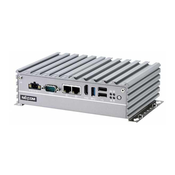
Page 19: Knowing Your Nise 105U
Indicates the power status, RTC battery status, storage activity and GPO activity of the system. Power Switch COM1 HDMI USB 2.0 Power Switch Press to power-on or power-off the system. Copyright © 2019 NEXCOM International Co., Ltd. All Rights Reserved. NISE 105U User Manual... -
Page 20: Rear Panel
Remote Switch DVI-I Optional I/F Two DB9 ports used to connect RS232 compatible devices. Optional I/F Expansion slot for optional function output or module interface use. Copyright © 2019 NEXCOM International Co., Ltd. All Rights Reserved. NISE 105U User Manual... -
Page 21: Mechanical Dimensions
Chapter 1: Product Introduction Mechanical Dimensions Ø 4.00 R4.00 Ø 3.20 184.85 194.00 206.00 Copyright © 2019 NEXCOM International Co., Ltd. All Rights Reserved. NISE 105U User Manual... -
Page 22: Chapter 2: Jumpers And Connectors
Static electricity can damage many of the electronic ▪ Use correct screws and do not over tighten screws. components. Humid environments tend to have less static electricity than Copyright © 2019 NEXCOM International Co., Ltd. All Rights Reserved. NISE 105U User Manual... -
Page 23: Jumper Settings
(on) and open (off). Two-Pin Jumpers: Open (Left) and Short (Right) Three-Pin Jumpers: Pins 1 and 2 are Short Copyright © 2019 NEXCOM International Co., Ltd. All Rights Reserved. NISE 105U User Manual... -
Page 24: Locations Of The Jumpers And Connectors For Nisb 105
Locations of the Jumpers and Connectors for NISB 105 NISB 105U The following figures are the top and bottom view of the NISB 105U main board which is the main board used in NISE 105U. It shows the locations of the jumpers and connectors. Top View TP11... - Page 25 Chapter 2: Jumpers and Connectors Bottom View EDP2 EDP1 SIM1 SATA1 JFW1 CN10 Copyright © 2019 NEXCOM International Co., Ltd. All Rights Reserved. NISE 105U User Manual...
-
Page 26: Jumpers And Dip Switches
RTC Switch (Default All Off) Connector type: 1x3 3-pin header, 2.0mm pitch Connector type: 2x2 DIP switch Connector location: JP5 Connector location: SW2 Function Function SRTC_TEST# 2-3* RTC_TEST# Copyright © 2019 NEXCOM International Co., Ltd. All Rights Reserved. NISE 105U User Manual... -
Page 27: Connector Pin Definitions
RS232 RS485 RS422 VIN_1_GND Definition Definition Definition VIN_1 SP1_DCD SP1_DATA- SP1_TX- SP1_RXD SP1_DATA+ SP1_TX+ SP1_TXD SP1_RX+ SP1_DTR SP1_RX- SP1_DSR SP1_RTS- SP1_RTS SP1_RTS+ SP1_CTS SP1_CTS+ SP1_RI SP1_CTS- Copyright © 2019 NEXCOM International Co., Ltd. All Rights Reserved. NISE 105U User Manual... -
Page 28: Lan1 And Lan2 Ports
LAN2_MDI0P LAN2_MDI0N LAN1_MDI1P LAN1_MDI1N LAN2_MDI1P LAN2_MDI1N LAN1_MDI2P LAN1_MDI2N LAN2_MDI2P LAN2_MDI2N LAN1_MDI3P LAN1_MDI3N LAN2_MDI3P LAN2_MDI3N V1P5_LAN V1P5_LAN2 LAN1_LINK100# LAN1_LINK1G# LAN2_LINK100# LAN2_LINK1G# LAN1_LED_ACT# 3VSB LAN2_LED_ACT# 3VSB CHASSIS_GND CHASSIS_GND Copyright © 2019 NEXCOM International Co., Ltd. All Rights Reserved. NISE 105U User Manual... -
Page 29: Hdmi
HDMI_DATA2_N HDMI_DATA1_P HUBUSB_DP1_C HDMI_DATA1_N USB3_RX0_N_C USB3_RX0_P_C HDMI_DATA0_P USB3_TX0_N_C HDMI_DATA0_N HDMI_CLK_P USB3_TX0_P_C P5V_OC01_C HDMI_CLK_N USB_1N_C USB_1P_C HDMI_CTRL_CLK HDMI_CTRL_DATA FRONT_GND FRONT_GND VCC5_HDMI FRONT_GND HDMI_HPD_R CHASSIS_GND CHASSIS_GND CHASSIS_GND CHASSIS_GND Copyright © 2019 NEXCOM International Co., Ltd. All Rights Reserved. NISE 105U User Manual... -
Page 30: Dual Usb 2.0 Port
Power/HDD LED (LED3) LED2 Definition Definition Definition USB2_5V USB_0N_C VCC5 USB_0P_C BAT_LED USB2_5V USB_1N_C USB_1P_C GPIO_LED_N FRONT_GND FRONT_GND LED3 FRONT_GND FRONT_GND Definition VCC5 VCC5 HDD_LED_N PWR_LED_N Copyright © 2019 NEXCOM International Co., Ltd. All Rights Reserved. NISE 105U User Manual... -
Page 31: Power Switch
Chapter 2: Jumpers and Connectors Power Switch Connector location: SW1 Definition Definition 3VSB 3VSB PWRLED_N PWRLED_P Copyright © 2019 NEXCOM International Co., Ltd. All Rights Reserved. NISE 105U User Manual... -
Page 32: External I/O Interfaces - Rear Panel
Connector location: CN4 Definition Definition Definition TX2- TX2+ REMO_PWRBTN# DDC_CLK DDC_DATA VSYNC_VGA TX1- TX1+ DVI_VCC(+5V) HotPlugDet TX0- TX0+ DDCCLK_VGA DDCDATA_VGA TXCLK+ TXCLK- GREEN BLUE HSYNC_VGA VGADET CHASSIS_GND CHASSIS_GND Copyright © 2019 NEXCOM International Co., Ltd. All Rights Reserved. NISE 105U User Manual... -
Page 33: Com2 Port
SP2_DCD SP2_DATA- SP2_TX- SP3_DCD SP3_RXD SP2_RXD SP2_DATA+ SP2_TX+ SP3_TXD SP3_DTR SP2_TXD SP2_RX+ SP3_DSR SP2_DTR SP2_RX- SP3_RTS SP3_CTS SP3_RI SP2_DSR SP2_RTS- SP2_RTS SP2_RTS+ SP2_CTS SP2_CTS+ SP2_RI SP2_CTS- Copyright © 2019 NEXCOM International Co., Ltd. All Rights Reserved. NISE 105U User Manual... -
Page 34: Com4 Port
Chapter 2: Jumpers and Connectors COM4 Port Connector type: DB-9 port, 9-pin D-Sub Connector location: CN1 RS232 Definition Definition SP4_DCD SP4_RXD SP4_TXD SP4_DTR SP4_DSR SP4_RTS SP4_CTS SP4_RI Copyright © 2019 NEXCOM International Co., Ltd. All Rights Reserved. NISE 105U User Manual... -
Page 35: Internal Connectors
Connector type: 2x3 6-pin header, 2.0mm Connector type: 1x4 4-pin header, 2.0mm pitch Connector location: JFW1 Connector location: JP2 Definition Definition Definition OUT_L CS#0 AGND OUT_R Copyright © 2019 NEXCOM International Co., Ltd. All Rights Reserved. NISE 105U User Manual... -
Page 36: Line-In Connector
Connector type: 1x4 4-pin header, 2.0mm pitch Connector type: 1x4 4-pin header, 2.0mm pitch Connector location: JP3 Connector location: JP4 Definition Definition FLIN_L MIC1_L3 MIC_GND FLIN_R MIC1_R3 Copyright © 2019 NEXCOM International Co., Ltd. All Rights Reserved. NISE 105U User Manual... -
Page 37: Sata Connector
Connector type: Standard Serial ATA 7P (1.27mm, SATA-M-180) Connector type: 1x2 2-pin header, JST 2.5mm pitch Connector location: SATA1 Connector location: J2 Definition Definition Definition SATA_TXP0_C VCC5 SATA_TXN0_C SATA_RXN0_C SATA_RXP0_C Copyright © 2019 NEXCOM International Co., Ltd. All Rights Reserved. NISE 105U User Manual... -
Page 38: Port 80 Connector
Connector location: J1 Connector location: JP6 Definition Definition Definition Definition VCC5 PLTRST_3P3# LPC_CLK0_DEBUG LPC_FRAME# ICH_GPO0_OUT ICH_GPI0_IN ICH_GPO1_OUT ICH_GPI1_IN LPC_AD3 LPC_AD2 LPC_AD1 LPC_AD0 ICH_GPO2_OUT ICH_GPI2_IN ICH_GPO3_OUT ICH_GPI3_IN VCC3 VCC3 Copyright © 2019 NEXCOM International Co., Ltd. All Rights Reserved. NISE 105U User Manual... -
Page 39: Reset Pin Header
Connector type: 2x7 14-pin header, 2.0mm pitch Connector location: JP9 Connector location: JP8 Definition Definition Definition PM_RESET#_J PWR_LED_N POWER_LED_PWR HDD_LED_N HDD_LED_PWR SMB_CLK SMB_DATA 3VSB SLP_S3# PSON PBT_SW PM_RESET#_J Copyright © 2019 NEXCOM International Co., Ltd. All Rights Reserved. NISE 105U User Manual... -
Page 40: Flash Mcu Pin Header
SIM Card Slot Connector type: 1x4 4-pin header, 2.0mm pitch Connector location: SIM1 Connector location: JP7 Definition Definition Definition 3VSB UIM_PWR UIM_RESET SBW_TCK UIM_CLK SBW_TDIO UIM_VPP UIM_DATA Copyright © 2019 NEXCOM International Co., Ltd. All Rights Reserved. NISE 105U User Manual... -
Page 41: Edp1 Connector
HUBUSB_DP4 USB_DP4_GPIO EDP_SMB_CLK HUBUSB_DN4 EDP_SMB_DAT 3VSB EDP_HPD EDP_PWM_CTRL VCC3 3VSB EDP_BKL_EN PLTRST VCC5 5VSB VCC3 VCC3 EDP_12v 5VSB VCC3 EDP_12v VCC5 VCC5 VCC5 EDP_12V EDP_12V EDP_12V Copyright © 2019 NEXCOM International Co., Ltd. All Rights Reserved. NISE 105U User Manual... -
Page 42: Mini-Pcie Slot
SMBCLK +1.5V PCIETX0- SMBDATA CLKREQ# UIM_PWR PCIETX0+ UIM_DATA USB_D- REF CLK- UIM_CLK USB_D+ REF CLK+ UIM_RESET +3VSB UIM_VPP +3VSB Disable# RST# +1.5V PCIERX0- +3VSB PCIERX0+ +3VSB Copyright © 2019 NEXCOM International Co., Ltd. All Rights Reserved. NISE 105U User Manual... -
Page 43: M.2 Key Connector
M.2 Key Connector Connector location: CN9 Definition Definition Definition Definition 3VSB SATA_TXN1_C 3VSB SATA_TXP1_C PLTRST_3P3# HUBUSB_DP2 N36291448 HUBUSB_DM2 N36291047 M.2_RESET M2_SUSCLK PCIE_mSATA_SEL 3VSB 3VSB 3VSB USB3_OTHER_SEL SATA_RXP1_C SATA_RXN1_C Copyright © 2019 NEXCOM International Co., Ltd. All Rights Reserved. NISE 105U User Manual... -
Page 44: Chapter 3: System Setup
1. Locate the 6 screws on the bottom side of the chassis cover. 2. Remove the 6 screws on the bottom side of the chassis cover. Copyright © 2019 NEXCOM International Co., Ltd. All Rights Reserved. NISE 105U User Manual... - Page 45 Chapter 3: System Setup 3. Remove the chassis cover. Copyright © 2019 NEXCOM International Co., Ltd. All Rights Reserved. NISE 105U User Manual...
-
Page 46: Installing A So-Dimm Memory Module
The ejector tabs at the ends of the socket will automatically snap into the locked position to hold the module in place. SO-DIMM Socket Memory Module Copyright © 2019 NEXCOM International Co., Ltd. All Rights Reserved. NISE 105U User Manual... -
Page 47: Installing A Wireless Lan Module (Half-Size)
Installing a Wireless LAN Module (Half-size) 1. Locate the mini-PCIe slot on the board. 2. Install the mini-PCIe bracket to the mini-PCIe module. Screw Mini-PCIe Slot Copyright © 2019 NEXCOM International Co., Ltd. All Rights Reserved. NISE 105U User Manual... - Page 48 4. Push the module down and secure it with a screw. until the gold-plated connector on the edge of the module completely disappears into the slot. Copyright © 2019 NEXCOM International Co., Ltd. All Rights Reserved. NISE 105U User Manual...
-
Page 49: Installing A Wireless Lan Module (Full-Size)
2. Insert the mini-PCIe module into the mini-PCIe slot at a 45-degree angle from the board. until the gold-plated connector on the edge of the module completely disappears into the slot. Mini-PCIe Slot Mini-PCIe Bracket Copyright © 2019 NEXCOM International Co., Ltd. All Rights Reserved. NISE 105U User Manual... - Page 50 Chapter 3: System Setup 3. Push the module down and secure it with a screw. Copyright © 2019 NEXCOM International Co., Ltd. All Rights Reserved. NISE 105U User Manual...
-
Page 51: Installing An M.2 Card
2. Make sure the gold-plated six-pin connector on the edge of the module is on the left, while the five-pin connector is on the right. Five-Pin Six-Pin M.2 Slot Copyright © 2019 NEXCOM International Co., Ltd. All Rights Reserved. NISE 105U User Manual... - Page 52 3. Insert the M.2 module into the M.2 slot at a 45-degree angle until the 4. Push the module down and secure it with a screw. gold-plated connector on the edge of the module completely disappears into the slot. Copyright © 2019 NEXCOM International Co., Ltd. All Rights Reserved. NISE 105U User Manual...
-
Page 53: Installing A Sim Card
Installing a SIM Card 1. Locate the SIM card holder and release the cover. 2. Place the SIM card into the holder. SIM Card SIM Card Cover Copyright © 2019 NEXCOM International Co., Ltd. All Rights Reserved. NISE 105U User Manual... - Page 54 Chapter 3: System Setup 3. Close the cover and secure it to the original position. Copyright © 2019 NEXCOM International Co., Ltd. All Rights Reserved. NISE 105U User Manual...
-
Page 55: Installing A Sata Storage Drive
Align the mounting holes of the SATA drive with the mounting will be the outer side of the cover. Use the provided screws to secure the holes on the cover. drive in place. Copyright © 2019 NEXCOM International Co., Ltd. All Rights Reserved. NISE 105U User Manual... - Page 56 Chapter 3: System Setup 3. Connect the SATA data/power cable to the SATA drive. 4. Connect the SATA data/power cable to connectors SATA1 and J2 on the motherboard respectively. Copyright © 2019 NEXCOM International Co., Ltd. All Rights Reserved. NISE 105U User Manual...
-
Page 57: Wall Mounting Instructions
Wall Mount Bracket Fasten screws to mount Specification of the wall mount screw: the system to the wall Round Head Screw Long Fei:P6#32Tx 1/4/SW7*0.8 w/Spring+Flat Washer Copyright © 2019 NEXCOM International Co., Ltd. All Rights Reserved. NISE 105U User Manual... -
Page 58: Chapter 4: Bios Setup
This chapter describes how to use the BIOS setup program for the NISE 105U. The settings made in the setup program affect how the computer performs. The BIOS screens provided in this chapter are for reference only and may change It is important, therefore, first to try to understand all the setup options, and if the BIOS is updated in the future. -
Page 59: Default Configuration
Powering on the computer and immediately pressing <Del> allows you to enter Setup. Load optimized default values. Press the key to enter Setup: Saves and exits the Setup program. Press <Enter> to enter the highlighted sub-menu. Copyright © 2019 NEXCOM International Co., Ltd. All Rights Reserved. NISE 105U User Manual... - Page 60 When “” appears on the left of a particular field, it indicates that a submenu which contains additional options are available for that field. To display the submenu, move the highlight to that field and press Copyright © 2019 NEXCOM International Co., Ltd. All Rights Reserved. NISE 105U User Manual...
-
Page 61: Bios Setup Utility
System Date [Fri 05/03/2019] F2: Previous Values System Time [15:55:08] F3: Optimized Defaults F4: Save & Exit ESC: Exit Version 2.16.1242. Copyright (C) 2013 American Megatrends, Inc. Copyright © 2019 NEXCOM International Co., Ltd. All Rights Reserved. NISE 105U User Manual... -
Page 62: Advanced
Select the highest ACPI sleep state the system will enter when the suspend button is pressed. The options are Suspend Disabled and S3 (Suspend to Version 2.16.1242. Copyright (C) 2013 American Megatrends, Inc. RAM). Copyright © 2019 NEXCOM International Co., Ltd. All Rights Reserved. NISE 105U User Manual... - Page 63 Displays the Super I/O chip used on the board. Enables or disables the serial port. Onboard Serial Port Mode Select this to change the serial port mode to RS232, RS422, RS485 or RS485 Auto. Copyright © 2019 NEXCOM International Co., Ltd. All Rights Reserved. NISE 105U User Manual...
- Page 64 Enables or disables the serial port. Enables or disables the serial port. Onboard Serial Port Mode Select this to change the serial port mode to RS232, RS422, RS485 or RS485 Auto. Copyright © 2019 NEXCOM International Co., Ltd. All Rights Reserved. NISE 105U User Manual...
- Page 65 F2: Previous Values F3: Optimized Defaults F4: Save & Exit ESC: Exit Version 2.16.1242. Copyright (C) 2013 American Megatrends, Inc. Serial Port Enables or disables the serial port. Copyright © 2019 NEXCOM International Co., Ltd. All Rights Reserved. NISE 105U User Manual...
- Page 66 CPU temperature(DTS) Detects and displays the current CPU temperature. System temperature Detects and displays the current system temperature. VCore Detects and displays the VCore CPU voltage. Copyright © 2019 NEXCOM International Co., Ltd. All Rights Reserved. NISE 105U User Manual...
- Page 67 Windows, this problem may occur. To avoid this problem, enable Version 2.16.1242. Copyright (C) 2013 American Megatrends, Inc. this field to limit the return value to 3 or lesser than 3. Copyright © 2019 NEXCOM International Co., Ltd. All Rights Reserved. NISE 105U User Manual...
- Page 68 F2: Previous Values F3: Optimized Defaults F4: Save & Exit ESC: Exit Version 2.16.1242. Copyright (C) 2013 American Megatrends, Inc. EIST Enables or disables Intel ® SpeedStep. Copyright © 2019 NEXCOM International Co., Ltd. All Rights Reserved. NISE 105U User Manual...
- Page 69 ESC: Exit Version 2.16.1242. Copyright (C) 2013 American Megatrends, Inc. Serial-ATA (SATA) Enables or disables SATA device. SATA Mode Configures the SATA as IDE or AHCI mode. Copyright © 2019 NEXCOM International Co., Ltd. All Rights Reserved. NISE 105U User Manual...
- Page 70 CSM Support Enables or disables CSM support. Network Controls the execution of UEFI and legacy PXE OpROM. Storage Controls the execution of UEFI and legacy storage OpROM. Copyright © 2019 NEXCOM International Co., Ltd. All Rights Reserved. NISE 105U User Manual...
- Page 71 This is a workaround for OSs that does not support XHCI hand-off and EHCI hand-off. The XHCI and EHCI ownership change should be claimed by the XHCI and EHCI driver respectively. Copyright © 2019 NEXCOM International Co., Ltd. All Rights Reserved. NISE 105U User Manual...
-
Page 72: Chipset
Version 2.16.1242. Copyright (C) 2013 American Megatrends, Inc. High Precision Timer Enables or disables the high precision event timer. Version 2.16.1242. Copyright (C) 2013 American Megatrends, Inc. Copyright © 2019 NEXCOM International Co., Ltd. All Rights Reserved. NISE 105U User Manual... - Page 73 Enabled Azalia will be unconditionally enabled. Auto Azalia will be enabled if present, disabled otherwise. Azalia HDMI Codec Enables or disables internal HDMI codec for Azalia. Copyright © 2019 NEXCOM International Co., Ltd. All Rights Reserved. NISE 105U User Manual...
- Page 74 EHCI controller must always be enabled. USB RMH Mode Enables or disables PCH USB rate matching hubs mode. USB EHCI Debug Enables or disables PCH EHCI debug capability. Copyright © 2019 NEXCOM International Co., Ltd. All Rights Reserved. NISE 105U User Manual...
-
Page 75: Security
Adjust the boot sequence of the system. Boot Option #1 is the first boot device that the system will boot from, next will be #2 and so forth. Copyright © 2019 NEXCOM International Co., Ltd. All Rights Reserved. NISE 105U User Manual... -
Page 76: Save & Exit
<Enter>. You may be prompted to confirm again before exiting. Restore Defaults To restore the BIOS to default settings, select this field then press <Enter>. A dialog box will appear. Confirm by selecting Yes. Copyright © 2019 NEXCOM International Co., Ltd. All Rights Reserved. NISE 105U User Manual... -
Page 77: Appendix A: Power Consumption
3. Measure the power consumption and record it. 4. Run Burn-in test program to apply 100% full loading. 5. Measure the power consumption and record it. Copyright © 2019 NEXCOM International Co., Ltd. All Rights Reserved. NISE 105U User Manual... -
Page 78: Appendix B: Gpi/O Programming Guide
GPI/O (General Purpose Input/Output) pins are provided for custom system design. This appendix provides definitions and its default setting for the ten GPI/O pins in NISE 105U. The pin definition is shown in the following table: PowerOn PowerOn... - Page 79 #define GPO1_LO outportb(0xA02, 0x00) #define GPO2_HI outportb(0xA07, GPO2) #define GPO2_LO outportb(0xA07, 0x00) #define GPO3_HI outportb(0xA07, GPO3) #define GPO3_LO outportb(0xA07, 0x00) void main(void) GPO0_HI; GPO1_LO; GPO2_HI; GPO3_LO; Copyright © 2019 NEXCOM International Co., Ltd. All Rights Reserved. NISE 105U User Manual...
-
Page 80: Appendix C: Watchdog Timer Setting
0x90); # Use the second # Use the minute, change value to 0x10 # Set WDT sec/min outportb(SUPERIO_PORT, WDT_VALUE); outportb(SUPERIO_PORT+1, 0x05); # Set 5 seconds Copyright © 2019 NEXCOM International Co., Ltd. All Rights Reserved. NISE 105U User Manual...
Need help?
Do you have a question about the NISE 105U and is the answer not in the manual?
Questions and answers