
Related Manuals for Nexcom NISE 505


Summary of Contents for Nexcom NISE 505
- Page 1 NEXCOM International Co., Ltd. IoT Automation Solutions Business Group Fan-less Computer NISE 505 User Manual NEXCOM International Co., Ltd. www.nexcom.com Published November 2019...
-
Page 2: Table Of Contents
Knowing Your NISE 505 ................4 BIOS Pin Header ................15 Front Panel ..................4 SATA Connector ................15 Rear Panel ...................4 SATA Power Connector ..............16 Mechanical Dimensions ................5 GPIO Pin Header ................16 Copyright © 2019 NEXCOM International Co., Ltd. All Rights Reserved. NISE 505 User Manual... - Page 3 5.1 Command Register and Address Description: ......60 Advanced ..................38 5.2 Read Description: ..............60 Chipset ....................46 5.3 Write Description: ..............60 Security .....................48 Boot ....................48 Save & Exit ..................49 Copyright © 2019 NEXCOM International Co., Ltd. All Rights Reserved. NISE 505 User Manual...
-
Page 4: Preface
Acknowledgements The product(s) described in this manual complies with all applicable NISE 505 is a trademark of NEXCOM International Co., Ltd. All other product European Union (CE) directives if it has a CE marking. For computer systems names mentioned herein are registered trademarks of their respective to remain CE compliant, only CE-compliant parts may be used. -
Page 5: Rohs Compliance
(Cr6+) < 0.1% or 1,000ppm, Polybrominated biphenyls (PBB) < 0.1% or 1,000ppm, and Polybrominated diphenyl Ethers (PBDE) < 0.1% or 1,000ppm. In order to meet the RoHS compliant directives, NEXCOM has established an engineering and manufacturing task force to implement the introduction of green products. -
Page 6: Warranty And Rma
(manuals, cable, etc.) and any components from the card, such as CPU and RAM. If the components were suspected as part of the problems, ▪ If RMA goods can not be repaired, NEXCOM will return it to the customer please note clearly which components are included. Otherwise, NEXCOM without any charge. -
Page 7: Installation Recommendations
Using your fingers can disconnect most of the connections. It is recommended that you do not use needle-nose pliers to disconnect connections as these can damage the soft metal or plastic parts of the connectors. Copyright © 2019 NEXCOM International Co., Ltd. All Rights Reserved. NISE 505 User Manual... -
Page 8: Safety Information
Discard used batteries according to the manufacturer’s instructions. ▪ This product is intended to be supplied by an approved power adapter, rated 12Vdc, 5A or 24Vdc, 2.5A minimum and Tma 55 degree Celsius. If further assistance is needed, please contact NEXCOM for further information. viii Copyright ©... -
Page 9: Safety Precautions
ACCORDING TO THE MANUFACTURER’S INSTRUCTIONS. 11. If the equipment is not used for a long time, disconnect it from the power source to avoid damage by transient overvoltage. Copyright © 2019 NEXCOM International Co., Ltd. All Rights Reserved. NISE 505 User Manual... -
Page 10: Technical Support And Assistance
Preface Technical Support and Assistance Conventions Used in this Manual 1. For the most updated information of NEXCOM products, visit NEXCOM’s Warning: website at www.nexcom.com. Information about certain situations, which if not observed, can cause personal injury. This will prevent injury to yourself 2. -
Page 11: Global Service Contact Information
16F, No.250, Sec. 2, Chongde Rd., Beijing, 100094, China Beitun Dist., Tel: +86-10-5704-2680 Taichung City 406, R.O.C. Fax: +86-10-5704-2681 Tel: +886-4-2249-1179 Email: sales@nexcom.cn Fax: +886-4-2249-1172 www.nexcom.cn Email: sales@nexcom.com.tw www.nexcom.com.tw Copyright © 2019 NEXCOM International Co., Ltd. All Rights Reserved. NISE 505 User Manual... - Page 12 Tokyo, 108-0014, Japan No. 609, Yunlin East Rd., Tel: +81-3-5419-7830 Shanghai, 200062, China Fax: +81-3-5419-7832 Tel: +86-21-5278-5868 Email: sales@nexcom-jp.com Fax: +86-21-3251-6358 www.nexcom-jp.com Email: renwang@nexcom.com.tw www.nexcom.cn Copyright © 2019 NEXCOM International Co., Ltd. All Rights Reserved. NISE 505 User Manual...
-
Page 13: Package Contents
Preface Package Contents Before continuing, verify that the package that you received is complete. Your NISE 505 package should have all the items listed in the following table. Item Part Number Description 19J00050502X0 NISE 505 ASSY 6012200052X00 PE Zipper Bag... -
Page 14: Ordering Information
Preface Ordering Information The following information below provides ordering information for NISE 505. NISE 505 (P/N: 10J00050502X0) - Intel Celeron processor J1900 quad core fanless system ® ® • 60W 12V/5A AC/DC power adapter w/o power cord (P/N: 7400060042X00) Copyright © 2019 NEXCOM International Co., Ltd. All Rights Reserved. -
Page 15: Chapter 1: Product Introduction
▪ 1 x mini-PCIe socket for optional mSATA storage ▪ 1 x RJ45 COM serial port for RS232 signal ▪ Support -5~55 degree C operating temperature ▪ Support 12V DC input Copyright © 2019 NEXCOM International Co., Ltd. All Rights Reserved. NISE 505 User Manual... -
Page 16: Hardware Specifications
▪ 4 x GPI and 4 x GPO (programmable to GPI or GPO) ▪ Relative humidity: 10% to 95% (non-condensing) ▪ Shock protection: – mSATA: 50G, half sine, 11ms, IEC60068-2-27 Copyright © 2019 NEXCOM International Co., Ltd. All Rights Reserved. NISE 505 User Manual... - Page 17 ▪ Vibration protection w/mSATA condition: – Random: 2Grms @ 5~500 Hz, IEC60068-2-64 – Sinusoidal: 2Grms @ 5~500 Hz, IEC60068-2-6 Certifications ▪ CE ▪ FCC Class A Copyright © 2019 NEXCOM International Co., Ltd. All Rights Reserved. NISE 505 User Manual...
-
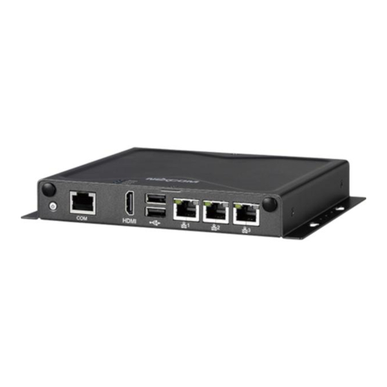
Page 18: Knowing Your Nise 505
USB 2.0 ports to connect the system with USB 2.0/1.1 devices. Rear Panel Used to connect the system to a local area network. DC Input Used to plug a DC power cord. DC Input Copyright © 2019 NEXCOM International Co., Ltd. All Rights Reserved. NISE 505 User Manual... -
Page 19: Mechanical Dimensions
Chapter 1: Product Introduction Mechanical Dimensions 186.00 174.00 4.00 Ø 8.00 Ø 3.70 162.00 Copyright © 2019 NEXCOM International Co., Ltd. All Rights Reserved. NISE 505 User Manual... -
Page 20: Chapter 2: Jumpers And Connectors
Static electricity can damage many of the electronic ▪ Use correct screws and do not over tighten screws. components. Humid environments tend to have less static electricity than Copyright © 2019 NEXCOM International Co., Ltd. All Rights Reserved. NISE 505 User Manual... -
Page 21: Jumper Settings
(on) and open (off). Two-Pin Jumpers: Open (Left) and Short (Right) Three-Pin Jumpers: Pins 1 and 2 are Short Copyright © 2019 NEXCOM International Co., Ltd. All Rights Reserved. NISE 505 User Manual... -
Page 22: Locations Of The Jumpers And Connectors For Nisb 505
Locations of the Jumpers and Connectors for NISB 505 NISB 505 The figure below is the top view of the NISB 505 main board which is the main board used in NISE 505. It shows the locations of the jumpers and connectors. DC-IN... -
Page 23: Jumpers And Switches
Connector type: 2-pin DIP switch Connector location: JP1 Connector location: SW2 Settings Definition 1-2 On ATX Mode SRTC_RST# 2-3 On AT Mode RTC_TEST# Definition 3VSB AT_ATX_SELECT Copyright © 2019 NEXCOM International Co., Ltd. All Rights Reserved. NISE 505 User Manual... -
Page 24: Connector Pin Definitions
Power Button RJ45 Console Port Connector location: SW1 Connector location: COM1 Definition Definition Definition Definition EC_PWRBT# COM1_RTS# COM1_DTR# EC_PWRBT# COM1_TXD PWR_SW_P PWR_SW_N COM1_RXD COM1_DSR# COM1_CTS# COM1_MH1 COM1_MH2 Copyright © 2019 NEXCOM International Co., Ltd. All Rights Reserved. NISE 505 User Manual... -
Page 25: Led Indicators
Definition Definition LED1 VCC3 SATA_LED# HDMI_DATA2_P_C LED2 VCC3 GPIO_PG0 HDMI_DATA2_N_C HDMI_DATA1_P_C LED3 VCC3 GPIO_PG1 HDMI_DATA1_N_C HDMI_DATA0_P_C HDMI_DATA0_N_C HDMI_CLK_P_C HDMI_CLK_N_C HDMI_CEC HDMI_CTRL_CLK_C HDMI_CTRL_DAT_C HDMI_PWR HDMI_HPD_R CHASSIS_GND CHASSIS_GND Copyright © 2019 NEXCOM International Co., Ltd. All Rights Reserved. NISE 505 User Manual... -
Page 26: Usb 2.0 Ports
Definition Definition Definition 4USBV1 DN1_C LAN1_MDI0P LAN1_MDI0N DP1_C LAN1_MDI1P LAN1_MDI1N 4USBV1 DN2_C LAN1TCT DP2_C LAN1_MDI2P LAN1_MDI2N CHASSIS_GND CHASSIS_GND LAN1_MDI3P LAN1_MDI3N CHASSIS_GND CHASSIS_GND LAN1_LINK1G# LAN1_LINK LAN1_LED_ACT# LAN1_ACTPW Copyright © 2019 NEXCOM International Co., Ltd. All Rights Reserved. NISE 505 User Manual... -
Page 27: Lan 2 Port
LAN2_MDI0P LAN2_MDI0N LAN3_MDI0P LAN3_MDI0N LAN2_MDI1P LAN2_MDI1N LAN3_MDI1P LAN3_MDI1N LAN2TCT LAN3TCT LAN2_MDI2P LAN2_MDI2N LAN3_MDI2P LAN3_MDI2N LAN2_MDI3P LAN2_MDI3N LAN3_MDI3P LAN3_MDI3N LAN2_LINK1G# LAN2_LINK LAN3_LINK1G# LAN3_LINK LAN2_LED_ACT# LAN2_ACTPW LAN3_LED_ACT# LAN3_ACTPW Copyright © 2019 NEXCOM International Co., Ltd. All Rights Reserved. NISE 505 User Manual... -
Page 28: External I/O Interfaces - Rear Panel
Chapter 2: Jumpers and Connectors External I/O Interfaces - Rear Panel DC Power Input Connector location: CN14 Definition VIN_VSS VIN_1 VIN_VSS VIN_1 Copyright © 2019 NEXCOM International Co., Ltd. All Rights Reserved. NISE 505 User Manual... -
Page 29: Internal Connectors
Connector type: 2x3 6-pin header, 2.0mm pitch Connector type: Standard Serial ATA 7P (1.27mm, SATA-M-180) Connector location: JFW1 Connector location: CN2 Definition Definition Definition Definition SATA_TXP0_C SATA_TXN0_C CS#0 SATA_RXN0_C SATA_RXP0_C Copyright © 2019 NEXCOM International Co., Ltd. All Rights Reserved. NISE 505 User Manual... -
Page 30: Sata Power Connector
Connector type: 2x5 10-pin header, 2.0mm pitch Connector location: J1 Connector location: JP2 Definition Definition Definition VCC5 VCC5 ICH_GPO0_OUT ICH_GPI0_IN ICH_GPO1_OUT ICH_GPI1_IN ICH_GPO2_OUT ICH_GPI2_IN ICH_GPO3_OUT ICH_GPI3_IN Copyright © 2019 NEXCOM International Co., Ltd. All Rights Reserved. NISE 505 User Manual... -
Page 31: Port Connector
Connector location: J2 Connector location: JP3 Definition Definition Definition Definition EC_PLTRST# PWR_LED_N VCC5 DEBUG_LPC33MHZ LPC_FRAME# SATA_LED# VCC5 LPC_AD3 LPC_AD2 3VSB LPC_AD1 LPC_AD0 SLP_S3# PS_ON# VCC3/LPC_SERIRQ VCC3 EC_PWRBT# PM_RESET#_J Copyright © 2019 NEXCOM International Co., Ltd. All Rights Reserved. NISE 505 User Manual... -
Page 32: Rtc Connector
EC Programmable Connector Connector type: 1x2 2-pin header, 1.25mm pitch Connector type: 1x3 3-pin header, 1.25mm pitch Connector location: J3 Connector location: J10 Definition Definition EC_SMBCLK VBAT_L EC_SMBDATA Copyright © 2019 NEXCOM International Co., Ltd. All Rights Reserved. NISE 505 User Manual... -
Page 33: Smbus Pin Header
Connector type: 2x4 8-pin header, 1.27mm pitch Connector location: JP8 Connector location: JP10 Definition Definition Definition Definition 3VSB VCC3 SMB_CLK SMB_DATA 3V3_SPI_CS 3V3_SPI_MISO 3V3_SPI_MOSI 3V3_SPI_CLK 3P3_I2C_CLK 3P3_I2C_DATA Copyright © 2019 NEXCOM International Co., Ltd. All Rights Reserved. NISE 505 User Manual... -
Page 34: Mini-Pcie Connector (Msata/Usb)
Mini-PCIe Connector (mSATA/USB) Connector location: CN5 Definition Definition Definition Definition 3VSB_MINI1 V1P5S_1 EC_SMBCLK V1P5S_1 SATA_TXN1_C EC_SMBDATA SATA_TXP1_C MINI1USBN MINI1USBP 3VSB_MINI1 3VSB_MINI1 MINICARD2DIS# V1P5S_1 SATA_RXP1_C 3VSB_MINI1 SATA_RXN1_C 3VSB_MINI1 3VSB_MINI1 Copyright © 2019 NEXCOM International Co., Ltd. All Rights Reserved. NISE 505 User Manual... -
Page 35: Mini-Pcie Connector (Wi-Fi/Usb)
Definition Definition Definition Definition PCIEWAKE# 3VSB_MINI2 V1P5S_2 EC_SMBCLK V1P5S_2 TXN0_R EC_SMBDATA MINICARD2CLKREQ# TXP0_R MINI2USBN PCIE_CLKN0 MINI2USBP PCIE_CLKP0 3VSB_MINI2 3VSB_MINI2 MINICARD2DIS# EC_PLTRST# V1P5S_2 RXN0_R 3VSB_MINI2 RXP0_R 3VSB_MINI2 Copyright © 2019 NEXCOM International Co., Ltd. All Rights Reserved. NISE 505 User Manual... -
Page 36: Chapter 3: System Setup
2. With the screws removed, lift up the cover and remove it from the chassis. screws each on the top and on the sides. Screws on the sides Copyright © 2019 NEXCOM International Co., Ltd. All Rights Reserved. NISE 505 User Manual... -
Page 37: Installing A So-Dimm Memory Module
The ejector tabs at the ends of the socket will automatically snap into the locked position to hold the module in place. Memory Module SO-DIMM Socket Copyright © 2019 NEXCOM International Co., Ltd. All Rights Reserved. NISE 505 User Manual... -
Page 38: Installing An Msata Mini-Pcie Module (Storage)
2. Insert the storage module into the mini-PCI Express slot at a 45 degree angle until the gold-plated connector on the edge of the module completely disappears inside the slot. Mini-PCIe Slot Copyright © 2019 NEXCOM International Co., Ltd. All Rights Reserved. NISE 505 User Manual... - Page 39 Chapter 3: System Setup 3. Push the module down and then secure it with mounting screws. Mounting Screw Copyright © 2019 NEXCOM International Co., Ltd. All Rights Reserved. NISE 505 User Manual...
-
Page 40: Installing A Wi-Fi/Bt Mini-Pcie Module (Half-Size)
1. Locate the mini-PCI Express slot (CN6) on the board. 2. Align the wireless LAN module to the module bracket and secure both together with screws. WLAN Module Module Bracket Mini-PCIe Slot Copyright © 2019 NEXCOM International Co., Ltd. All Rights Reserved. NISE 505 User Manual... - Page 41 4. Push the module down and then secure it with mounting screws. degree angle until the gold-plated connector on the edge of the module completely disappears inside the slot. Mounting Screw Copyright © 2019 NEXCOM International Co., Ltd. All Rights Reserved. NISE 505 User Manual...
-
Page 42: Installing An Antenna
2. Insert the SMA antenna jack end of the cable through the antenna hole, and insert the 2 rings (ring 1 and ring 2) back to the antenna jack. Ring 2 Ring 1 Copyright © 2019 NEXCOM International Co., Ltd. All Rights Reserved. NISE 505 User Manual... - Page 43 Chapter 3: System Setup 3. Attach the RF cable onto the module. RF Cable 4. Connect the external antenna to the antenna jack. Copyright © 2019 NEXCOM International Co., Ltd. All Rights Reserved. NISE 505 User Manual...
-
Page 44: Wall Mount Installation
1. Align the M4 mounting holes on the chassis cover to the desired bracket. Before wall mounting the system, please ensure the top installation location. cover is secured with 6 screws. (Screw specifications: M3x4mm) Mounting Holes Copyright © 2019 NEXCOM International Co., Ltd. All Rights Reserved. NISE 505 User Manual... - Page 45 Chapter 3: System Setup 2. Mount the system by fastening 4 screws through the mounting holes. Copyright © 2019 NEXCOM International Co., Ltd. All Rights Reserved. NISE 505 User Manual...
-
Page 46: Din Rail Clip Installation
DIN Rail Clip Installation 1. Align the DIN rail clips to the mounting holes on the chassis cover. 2. Secure the DIN rail clips with screws. Mounting holes Copyright © 2019 NEXCOM International Co., Ltd. All Rights Reserved. NISE 505 User Manual... -
Page 47: Aluminum Din Rail Clip Installation
1. Align the aluminum DIN rail clip to the mounting holes on the chassis cover. 2. Secure the aluminum DIN rail clip with screws. Mounting holes Copyright © 2019 NEXCOM International Co., Ltd. All Rights Reserved. NISE 505 User Manual... -
Page 48: Chapter 4: Bios Setup
This chapter describes how to use the BIOS setup program for NISE 505. The The settings made in the setup program affect how the computer performs. BIOS screens provided in this chapter are for reference only and may change It is important, therefore, first to try to understand all the setup options, and if the BIOS is updated in the future. -
Page 49: Default Configuration
Powering on the computer and immediately pressing <Del> allows you to enter Setup. Load optimized default values. Press the key to enter Setup: Saves and exits the Setup program. Press <Enter> to enter the highlighted sub-menu Copyright © 2019 NEXCOM International Co., Ltd. All Rights Reserved. NISE 505 User Manual... - Page 50 When “” appears on the left of a particular field, it indicates that a submenu which contains additional options are available for that field. To display the submenu, move the highlight to that field and press Copyright © 2019 NEXCOM International Co., Ltd. All Rights Reserved. NISE 505 User Manual...
-
Page 51: Bios Setup Utility
F2: Previous Values System Date [Sun 01/01/2012] F3: Optimized Defaults System Time [00:00:54] F4: Save & Exit ESC: Exit Version 2.16.1242. Copyright (C) 2013 American Megatrends, Inc. Copyright © 2019 NEXCOM International Co., Ltd. All Rights Reserved. NISE 505 User Manual... -
Page 52: Advanced
F2: Previous Values option may not be effective with some OS. F3: Optimized Defaults F4: Save & Exit ESC: Exit Version 2.16.1242. Copyright (C) 2013 American Megatrends, Inc. Copyright © 2019 NEXCOM International Co., Ltd. All Rights Reserved. NISE 505 User Manual... - Page 53 Version 2.16.1242. Copyright (C) 2013 American Megatrends, Inc. button is pressed. The options are Suspend Disabled and S3 (Suspend to Super IO Chip RAM). Displays the Super I/O chip used on the board. Copyright © 2019 NEXCOM International Co., Ltd. All Rights Reserved. NISE 505 User Manual...
- Page 54 CPU temperature(DTS) Detects and displays the current CPU temperature. System temperature1 Detects and displays the current system temperature. VCore to VCC5 Detects and displays the output voltages. Copyright © 2019 NEXCOM International Co., Ltd. All Rights Reserved. NISE 505 User Manual...
- Page 55 Windows, this problem may occur. To avoid this problem, enable this field to limit the return value to 3 or lesser than 3. Version 2.16.1242. Copyright (C) 2013 American Megatrends, Inc. Copyright © 2019 NEXCOM International Co., Ltd. All Rights Reserved. NISE 505 User Manual...
- Page 56 This option configures the Serial ATA drives to use AHCI (Advanced Host Controller Interface). AHCI allows the storage driver to enable the advanced Serial ATA features which will increase storage performance. Copyright © 2019 NEXCOM International Co., Ltd. All Rights Reserved. NISE 505 User Manual...
- Page 57 SCC eMMC 4.5 DDR50 Support Enables or disables SCC eMMC 4.5 DDR50 support. SCC eMMC 4.5 HS200 Support Enables or disables SCC eMMC 4.5 HS200 support. Copyright © 2019 NEXCOM International Co., Ltd. All Rights Reserved. NISE 505 User Manual...
- Page 58 CSM Support Enables or disables CSM support. Network Controls the execution of UEFI and legacy PXE OpROM. Storage Controls the execution of UEFI and legacy storage OpROM. Copyright © 2019 NEXCOM International Co., Ltd. All Rights Reserved. NISE 505 User Manual...
- Page 59 This is a workaround for OSs that does not support XHCI hand-off and EHCI hand-off. The XHCI and EHCI ownership change should be claimed by the XHCI and EHCI driver respectively. Copyright © 2019 NEXCOM International Co., Ltd. All Rights Reserved. NISE 505 User Manual...
-
Page 60: Chipset
Version 2.16.1242. Copyright (C) 2013 American Megatrends, Inc. Restore AC Power Loss Select the AC power state when power is re-applied after a power failure. South Bridge Enters the South Bridge submenu. Copyright © 2019 NEXCOM International Co., Ltd. All Rights Reserved. NISE 505 User Manual... - Page 61 EHCI controller must always be enabled. USB RMH Mode Enables or disables PCH USB rate matching hubs mode. USB EHCI debug Enables or disables PCH EHCI debug capability. Copyright © 2019 NEXCOM International Co., Ltd. All Rights Reserved. NISE 505 User Manual...
-
Page 62: Security
#2 and so forth. Hard Drive BBS Priorities Sets the order of the legacy devices in this group. Copyright © 2019 NEXCOM International Co., Ltd. All Rights Reserved. NISE 505 User Manual... -
Page 63: Save & Exit
<Enter>. You may be prompted to confirm again before exiting. Restore Defaults To restore the BIOS to default settings, select this field then press <Enter>. A dialog box will appear. Confirm by selecting Yes. Copyright © 2019 NEXCOM International Co., Ltd. All Rights Reserved. NISE 505 User Manual... -
Page 64: Appendix A: Power Consumption
Functional Port Front / Rear Panel USB 2.0 x2 5V, 0.5A (Cement Resistor) COM 1 RS232 Loopback (115200 baud rate) HDMI LCD Monitor Keyboard & Mouse Copyright © 2019 NEXCOM International Co., Ltd. All Rights Reserved. NISE 505 User Manual... - Page 65 6.6 W ACPI Sleep (S3) Mode Power Consumption 12 V 0.2 A 2.4 W 100% Full Loading Mode Power Consumption 12 V 1.76 A 21 W Copyright © 2019 NEXCOM International Co., Ltd. All Rights Reserved. NISE 505 User Manual...
-
Page 66: Appendix B: Ec Command Documentation
This signals the embedded controller that the data has been read by the host and the embedded controller is free to write more data to the host. Copyright © 2019 NEXCOM International Co., Ltd. All Rights Reserved. NISE 505 User Manual... -
Page 67: Hw Monitor
VCORE (MSB: 0xB9 LSB: 0xBA) (Decimal point two) Wait OBF set 0xBB-0xBC TEMP_SENSOR (MSB: 0xBB LSB: 0xBC) Get HW monitor Read 0x62 port data in current >i 0x62 address Copyright © 2019 NEXCOM International Co., Ltd. All Rights Reserved. NISE 505 User Manual... -
Page 68: Fan Rpm
Write RAM address address 0x72 or >o 0x62 0x72 to 0x62 port 0x73. Wait OBF set Get Fan1 RPM data Read 0x62 port >i 0x62 in current address Copyright © 2019 NEXCOM International Co., Ltd. All Rights Reserved. NISE 505 User Manual... -
Page 69: Watchdog
To set up watchdog time interval to 4 seconds, here are the values that should be filled in each address. 4sec = 400ms (decimal) = 190 (hexadecimal) Address 0x50 0x51 0x52 0x53 Data 0x00 0x00 0x01 0x90 Copyright © 2019 NEXCOM International Co., Ltd. All Rights Reserved. NISE 505 User Manual... -
Page 70: Reset Watchdog Time Interval Description
Send stop watchdog >o 0x66 0x29 0x66 command Wait OBF set If setup is successful, Read 0x62 port (check 0x02 output EC will return 0x02. on display) Copyright © 2019 NEXCOM International Co., Ltd. All Rights Reserved. NISE 505 User Manual... -
Page 71: Gpio Control
0x10 Input 0x10Pull-up If type control is output type, 1-default output high and 0x01 Output 0x01Pull-dn 0-default output low. Copyright © 2019 NEXCOM International Co., Ltd. All Rights Reserved. NISE 505 User Manual... -
Page 72: Read Gpio Status Sequence
0x62 port Write 0x00, GPIO pin Read 0x62 port >i 0x62 set in index. will be set low. 1-GPIO is high. 0-GPIO is low. 0xFF-fail. Copyright © 2019 NEXCOM International Co., Ltd. All Rights Reserved. NISE 505 User Manual... -
Page 73: Read Gpio Direction Sequence
0x62 port Write 0x80, GPIO pin Read 0x62 port >i 0x62 set in index. will be set input. 0x80-input, 0x40- output. 0xFF-fail Copyright © 2019 NEXCOM International Co., Ltd. All Rights Reserved. NISE 505 User Manual... -
Page 74: Led Control
Write 0x81 to 0x66 >o 0x66 0xF0 command Wait IBF clear Send control cata Write RAM address 0x01 to enable >o 0x62 0x01 to 0x62 port Copyright © 2019 NEXCOM International Co., Ltd. All Rights Reserved. NISE 505 User Manual...
Need help?
Do you have a question about the NISE 505 and is the answer not in the manual?
Questions and answers