
Related Manuals for Krone Swadro 1010


Summary of Contents for Krone Swadro 1010
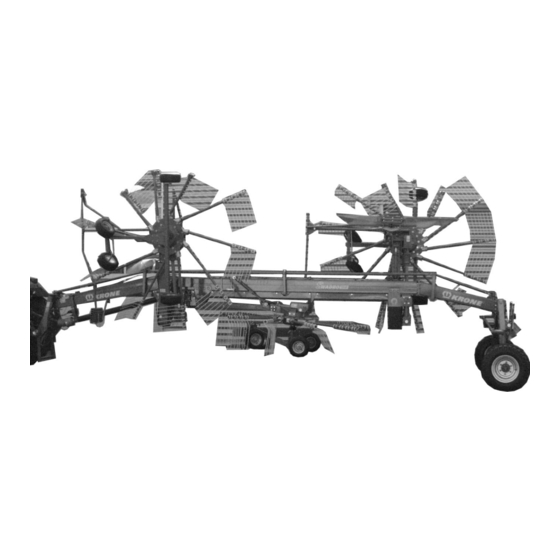
- Page 1 Operating Instructions 150 000 031 00 EN Rotary swather Swadro 1010 (from Machine No. 571 968)
- Page 2 (Dr.-Ing. Josef Horstmann, Business Director) (ppa. Dr.-Ing. Klaus Martensen, Engineering Director) Dear customer, Here are the operating instructions for the KRONE product you purchased. This operating manual contains important information for the pro- per use and safe operation of the machine.
- Page 3 We hope that you will be satisfied with your KRONE machine. Machine factory Bernard Krone GmbH Spelle...
- Page 4 Foreword...
-
Page 5: Table Of Contents
Attachment of swather to tractor ................III -2 3.3.1 Attachment to the tractor lower link arms .............. III -2 3.3.2 Hydraulic connection Swadro 1010 ................ III -3 3.3.3 Lighting cable connection ..................III -4 3.3.4 Connecting the electric control unit ................. III -4 3.3.5... - Page 6 List of contents Handling the swather when in use ..........IV -1 Mounting on the tractor ..................IV -1 Overload protection feature ................... IV -1 Converting from transport to working position ............IV -2 4.3.1 Lowering the rotor arms ..................IV -2 4.3.2 Folding the tine arms into working position .............
- Page 7 List of contents Lubrication chart ....................VI -5 Accessories ................... VIII - 1 Tine loss prevention feature (Accessory) ............VIII - 1 Chain for limiting depth of lower link arms (Accessory) ........VIII - 1 Winter storage ................... IX -1 Starting up again ................X -1 Faults –...
- Page 8 List of contents...
-
Page 9: General Information
The rotary swather is used to swath cut hay. It is installed inside the CAT II three-point hitch at the rear. 1.2 Specifications 1.2.1 Manufacturer's Address Maschinenfabrik Bernard Krone GmbH Heinrich-Krone-Straße 10 Maschinenfabrik Bernard Krone GmbH D-48480 Spelle (Germany) Heinrich-Krone-Str. 10 D-48480 Spelle... -
Page 10: Proper Use
1.2.5 General Specifications Driving on roads is only permissible with themachine in the transport position. Type Swadro 1010 Draft arm hitch standard Number of rotors Number of arms/rotor 10 / 13 /13... - Page 11 General Information SW101014 SW101015 I - 3...
- Page 12 General Information I - 4...
-
Page 13: Safety
Safety Before driving on public roads and 2.1 Identifying Safety Instructions in before every start check the machine for traffic and operational safety! the Operating Manual 2.3 Safety Instructions and The safety instructions contained in these instructions, Accident Prevention which could result in personal injury if not followed, are identified by the general danger sign: Regulations 1. -
Page 14: Trailer Implements
15. Actuating mechanisms (cables, chains, linkages etc.) for remote controlled devices must be positioned in such 1. Use only PTO shafts specified by the manufacturer! a way that no movements are unintentionally triggered at any transport or working positions. 2. The guard tube and guard cone of the PTO and the PTO guard must be attached and in good working 16. -
Page 15: Hydraulic System
2.3.4 Tyres 15. Place the disconnected PTO shaft onto the bracket provided! 1. When working on the tyres, make sure that the 16. After removing the PTO shaft, attach the protective implement has been safely lowered and secured cover to the PTO shaft end! against rolling (wheel chocks). -
Page 16: Maintenance
9. Replacement parts must at least comply with the technical requirements set by the manufacturer of the implements! This is guaranteed when using genuine KRONE replacement parts! 10. Only use nitrogen for filling pneumatic accumulators - Risk of explosion! -
Page 17: Introduction
2.4 Introduction The KRONE rotary swather is equipped with all necessary safety devices (protective equipment). Not all potentially dangerous positions on this implement can be fully secured, as this would be incompatible with full functional capability. You will find appropriate danger notification (= warning signs in yellow/black), indicating these residual risks. - Page 18 right left left/right left/right SW101002 Pull the guard bar down into protection position before carrying out work (fold down). Danger in swather disk operating area - keep your distance! 939 574-0 Order no. 939 574-0 (2x) Order no. 939 472-2 (8x) Never put your hand into the danger area as long as parts Do not remain in the slewing range...
- Page 19 ATTENTION ! VEHICLE UNREEVES Keep the stipulated safe distance to power transmission lines. Order no. 942 293-0 (2x) Order no. 27 000 091 0 (1x) Note: If the safety signs are damaged or missing, they must be replaced with new signs. The order numbers are stated next to the warning signs! II - 7...
-
Page 20: Location Of The General Information Signs On The Machine
2.4.2 Location of the General Information Signs on the Machine SW101003 942 301-0 (4x) 942 463-0 (2x) Swadro 1010 (lg.= 775 mm) (lg.= 647 mm) 942 320-0 (1x) 939 420-1 (1x) 942 517-0 (1x) Swadro 1010 (lg.=600 mm) (lg.= 510 mm) -
Page 21: General Preparation For Use
Preparing for Operation General preparation for use 3.1 Special safety instructions • Always turn off PTO shaft before carrying out servicing, maintenance, repair or assembly work on the rotary swather. Shut down the engine and remove the ignition key. Secure tractor and rotary swather against rolling away! •... -
Page 22: Attachment Of Swather To Tractor
Preparing for Operation 3.3 Attachment of swather to tractor • During all care, maintenance, repair and assembly work on the rotary swather, switch off the PTO, shut down the engine, remove the ignition key. Secure the tractor and rotary swather against rolling away! It is assumed in the following description, that after final assembly, the swather is in... -
Page 23: Hydraulic Connection Swadro 1010
Preparing for Operation 3.3.2 Hydraulic connection Swadro 1010 • When connecting the hydraulic hoses to the tractor hydraulics relieve all pressures from the system at either side. • When connecting the rapid action couplings, make sure that they are clean and dry. Soiling will result in leaks and damage. -
Page 24: Lighting Cable Connection
Preparing for Operation 3.3.3 Lighting cable connection The lighting system is connected via the lighting plug (1). Establish the connection between tractor and swather with the 7-cord cable provided. • Connect lighting plug (1) to the lighting socket of the tractor. -
Page 25: Function Of The Switches On The Control Unit
Preparing for Operation 3.3.5 Function of the switches on the control unit Always activate one function only on the control unit. The switches of all other functionss must be set to neutral. The following table shows the function of the different switches. -
Page 26: Connecting The Pto Shaft
Preparing for Operation 3.3.6 Connecting the PTO Shaft • Swing the PTO shaft holder (1) upwards. • Slide PTO shaft (2) onto PTO end. • Prevent shaft protection with holding chain from rotating with the shaft (wide angle at implement). A protective device must be used on the tractor and the machine. -
Page 27: Driving And Transport
Preparing for Operation 3.4 Driving and Transport 3.4.1 General on Driving The following should be observed when the rotary swather is driven: • Due to the rear wheel steering the handling of the rotary swather requires a certain time to get used to. •... - Page 28 Preparing for Operation III - 8...
-
Page 29: Handling The Swather When In Use
Handling the swather when in use Handling the swather when in use 4.1 Mounting on the tractor • When attaching the rotary swather make sure that no-one remains between the implement and the tractor. • No-one may remain in the slewing range of the swather disk arms! As described in Point 3.3, attach the swather to the tractor, couple the universal drive shaft and secure. -
Page 30: Converting From Transport To Working Position
Handling the swather when in use 4.3 Converting from transport to working position Before lowering the rotor, make certain there is no one in the slewing range of the rotor! Do not run the swather disks in the transport position or with retracted guard bar! 4.3.1 Lowering the rotor arms When switching from the transport to the working... -
Page 31: Folding The Tine Arms Into Working Position
Handling the swather when in use 4.3.2 Folding the tine arms into working position Shut down the engine and remove the ignition key. Secure tractor and rotary swather against rolling away! Fold the tine arms from transport to working position. •... -
Page 32: Moving The External Guard Bars Into Working Position
Handling the swather when in use 4.3.3 Moving the external guard bars into working position Guard front left Swivel the side hoop guard (1) on the front left of the machine outward in the working position and lock it in place with a hitch pin (2). -
Page 33: Swaths Without A Swath Cloth
Handling the swather when in use 4.3.4 Swaths without a swath cloth • Remove the linch pin (1). • Rotate the safety flap (2) back to position (II) and secure it in place with the linch pin (1). • Pull the spring cotter pin (3) away from the locking bolt (4). - Page 34 Handling the swather when in use Guard back right • Loosen the set screw (5). • Insert the swath cloth (6). • Tighten the set screw (5) and secure it in place. • Pull the spring cotter pin (4) away from the locking bolt (3).
-
Page 35: Folding The Tine Arms Into Transport Position
Handling the swather when in use 4.4.2 Folding the tine arms into transport position Shut down the engine and remove the ignition key. Secure tractor and rotary swather against rolling away! Fold the tine arms from working to transport position. First: •... -
Page 36: Lifting The Rotor Arms
Handling the swather when in use 4.4.3 Lifting the rotor arms • Disengage the lock via the actuating cable and set the tractor hydraulics actuation lever to „Lift“. • Keep pulling the actuating cable until the pin on the swather arm has gone past the engagement point for the working position. -
Page 37: Securing The Tine Tips (Transport Position And Parked Swather
Handling the swather when in use 4.4.4 Securing the tine tips (transport position and parked swather) Tines that are located below 2 m when the machine is in transport position or parked, must be secured with a tine guard. The tine guards are located on the front and centre hoop guards of the rotors. -
Page 38: Removal From Tractor
Handling the swather when in use 4.5 Removal from tractor • Make sure when setting down the swather disk, that the ground is even and firm! • Secure swather against rolling away before uncoupling! • Also observe all further safety instructions! •... - Page 39 Handling the swather when in use • Remove chocks (1) from chassis and place them in front and/or behind the wheels. • Lower the lower link until the swather rests on the support. Uncouple the swather. SW101024 IV - 11...
- Page 40 Handling the swather when in use IV - 12...
-
Page 41: Basic Setting
Basic setting Basic setting The basic setting should be undertaken on even surfaces. Keep a safe distance from the swather disk when it's turning! Before switching on the PTO shaft, ensure that no-one could be caught by the swather disk. When the PTO shaft is running, the swather arms may only be raised to just before their stops. -
Page 42: Setting The Operating Width
Basic setting 5.2 Setting the Operating Width The working depth for the swather disks is adjusted via three drive motors. Switch 2 = swather disk front left-hand Switch 3 = swather disk middle Switch 4 = swather disk back right hand Pressing the switch >... -
Page 43: Setting The Lateral Inclination Of The Swather Disk Chassis
Basic setting 5.3 Setting the lateral inclination of the swather disk chassis To achieve optimal work results, the transverse inclination of the rotors can be changed on the rear guide wheels (left + right) of the running gears. 5.3.1 Setting of the rotor running gear on the front rotor Do not step under the lifted rotors. -
Page 44: Adjusting The Direction Of Travel
Basic setting 5.4 Adjusting the Direction of Travel The direction of travel of the rear running gear can be adjusted by adjusting the suspension arm (1). • Loosen counter-nut (2). • Adjust suspension arm. Shorter suspension arm => Adjusts the machine further to the left Longer suspension arm =>... -
Page 45: Adjustable Throttles
Basic setting 5.6 Adjustable throttles You can use the adjustable throttles to adjust the lowering speeds of the rotors on the machine. The throttles are set in the factory so that the rotor is raised into the headland position or out of the headland position into the working position with a time delay (front, centre, rear). -
Page 46: Setting Of The Scraper
Basic setting 5.7 Setting of the scraper The scraper (1) can be adjusted to ensure a neat transfer of crop from the centre rotor to the right rear rotor. • Loosening the screw coupling (2) adjusts the height of the scraper. •... -
Page 47: Adjusting The Ground Pressure On The Rear Rotor Running Gear
Basic setting 5.9 Adjusting the Ground Pressure on the Rear Rotor Running Gear The ground pressure of the outer tyre on the rear rotor running gear can be relieved using the spring (1). To do this: • Move the machine to the headland position •... - Page 48 Basic setting V - 8...
-
Page 49: Care And Maintenance
Care and maintenance Care and maintenance Special safety instructions • Repair, maintenance and cleaning work as well as the rectification of malfunctions may only ever be carried out with the drive is switched off and the engine is at a stand still! – Remove the ignition key! •... -
Page 50: Tyres
• Set down rotary swather on firm, even ground. Prevent unintended rolling away with wedges. • Regularly check that wheel nuts are properly seated and tighten if necessary! • Regularly check air pressure! 6.3.1 Air pressure Swadro 1010 Tyres Tyre pressure Check the tyre pressure at regular intervals (100 h) and [bar] refill if necessary. -
Page 51: Frame Flanges
Care and maintenance 6.3.3 Frame flanges After first time use, the screws on the frame flanges must be retightened. 210 Nm). SW101041 Replacing the tine arms (in case of repair) In case of repair, the tine arms can be individually replaced by demounting. - Page 52 Care and maintenance VI - 4...
-
Page 53: Lubrication
Lubrication Lubrication Repair, maintenance and cleaning work as well as the rectification of malfunctions may only ever be carried out with the drive is switched off and the engine is at a stand still! — Remove the ignition key! All lubrication points are indicated on this pages. Observing the maintenance and lubrication intervals here will ensure a long service life for your machine. -
Page 54: Lubricant Quantities And Designations For The Gearboxes
Lubrication 7.3 Lubricant quantities and designations for the gearboxes Bio-lubricants Volume ltr. Name/Brand Oil change Name/Brand Swather disk gearbox Flowing gearbox grease Service life GFO 35 grease lubricated Pass-through gearbox SAE 90 about 1000 ha. on request 2x0,7 SAE 90 Front about 1000 ha. - Page 55 Lubrication 7.5 Front drive gear The front drive gear consists of an upper and lower gearbox. Upper part of the front drive gear Oil inspection • Intervals see section 7.3 • Remove check screw (1) • Oil level up to bore hole •...
-
Page 56: Rear Drive Gear
Lubrication 7.6 Rear drive gear The rear drive gear consists of an upper and lower gearbox. Upper part of the rear drive gear Oil inspection • Intervals see section 7.3 • Remove check screw (1) • Oil level up to bore hole •... -
Page 57: Lubrication Chart
Lubrication 7.7 Lubrication chart For reasons of clarity, each of the lubricating points are shown at one position of the rotary swather. There are also lubricating points on the other side at the corresponding positions (mirror-image). VII - 5... - Page 58 Lubrication VII - 6...
-
Page 59: Accessories
Accessories Accessories • It is essential for all care, maintenance, repair and assembly work on the rotary swather that the PTO shaft is switched off. • Shut down the engine and remove the ignition key. • Secure tractor and rotary swather against rolling away! Tine loss prevention feature (Accessory) Mounting the tine loss prevention feature The tine loss prevention feature for the twin-spring tines... - Page 60 Accessories VIII - 2...
-
Page 61: Winter Storage
• Make a list of all spare parts required and order in good time. It is easier for your KRONE to supply and install spare outside high-season. In addition the machine is then fully prepared for the coming summer. - Page 62 Winter storage IX - 2...
-
Page 63: Starting Up Again
Starting up again 10 Starting up again • Wipe off the oil and grease applied as preservative to the chains and inside the machine. • Thoroughly degrease the machine. Hence condensation which has possibly collected in the bearings is removed. •... - Page 64 Starting up again X - 2...
-
Page 65: Faults - Causes And Remedy
Faults – Causes and Remedy Faults – Causes and Remedy 11.1 Special Safety Instructions • The following general rules apply to all maintenance, assembly, repair and adjustment work: Bring the machine to a complete standstill. Switch off the motor. Remove ignition key. - Page 66 Faults – Causes and Remedy XI- 2...
- Page 67 Appendix A1 Appendix assembly instructions (initial assembly) A1.1 Preparations • It is essential that the PTO shaft is switched off for all care, maintenance, repair and assembly work on the rotary swather. • Shut down the engine and remove the ignition key. •...
- Page 68 Appendix A1.3 Rotating the front and back rotor running gears The front and rear rotor running gears must be switched while the machine is in working position. • Move the machine to the working position. • Remove the rotor running gear (1) by loosening the screw points (2) from the rotor (3).
- Page 69 Appendix A1.5 Assembly of the tine arms on the front and rear rotor When mounting the tine arms, always make certain that the folding tine arms are installed one after the other. Front rotor: 3 folding tine arms (4 tines) Centre rotor: 6 rigid tine arms (4 tines) Rear rotor:...
- Page 70 Appendix A1.6 Montage der Zinkenarme am mittleren Kreisel • Verschraubungen (1) am Zinkenarm lösen • Die vier Zinken (2) nach außen schieben und wie in nebenstehender Abb. dargestellt montie- ren. When tightening the screw connections (1), press the tines (2) slightly upward so they are resting on the fastening clamp (3).
- Page 71 Appendix A1.9 Installing the swath rubber The swath rubber is mounted between the swather disks, below the longitudinal frame. The angle rail (5) is mounted on the machine ex-works. Reinforcement (1) (BD 3 x 40 x 540; 4 pieces) Steel bar (2) (Rd 20 x 595) Swath blanket (3) Steel strip (4) (Bd 2 x 30 x 1065;...
- Page 72 Appendix A1.11 Attaching the warning signs • Install the warning panel support (1) on the drive frame. • Install the forward cotter support (2) on the warning panel support (1) and insert the wheel chock (3) in the retainer (2). •...
- Page 73 Appendix A1.12 Diagrams A - 7...
- Page 74 . . konsequent, kompetent Maschinenfabrik Bernard Krone GmbH Heinrich-Krone-Straße 10, D-48480 Spelle Postfach 11 63, D-48478 Spelle Phone +049 (0) 59 77/935-0 +049 (0) 59 77/935-339 Internet: http://www.krone.de eMail: info.ldm@krone.de...
Need help?
Do you have a question about the Swadro 1010 and is the answer not in the manual?
Questions and answers