
Related Manuals for Krone Swadro TC 640


Summary of Contents for Krone Swadro TC 640
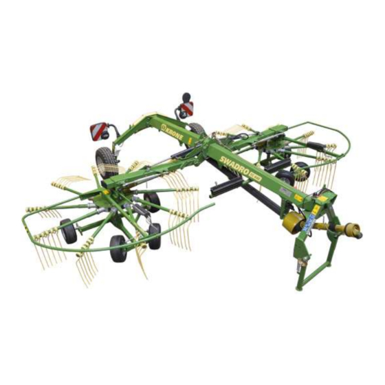
- Page 1 Rotary Rake Swadro TC 640 (from serial no.: 1 000 245) Order no.: 150 000 686 03 en 26.09.2018...
- Page 2 Table of Contents EC Declaration of Conformity Maschinenfabrik Krone Beteiligungs-GmbH Heinrich-Krone-Str. 10, D-48480 Spelle hereby declare as manufacturer of the product named below, on our sole responsibility, that the Rotor Rake Machine: Type: Swadro TC 640 to which this declaration refers is in compliance with the following relevant provisions of: •...
-
Page 3: Table Of Contents
Table of Contents Table of Contents Table of Contents ........................... 3 To this Document ........................... 6 Validity ..............................6 Re-Ordering ............................6 Further applicable documents ......................6 Target group of this document ......................6 How to use this document ........................6 2.5.1 Directories and References ...................... - Page 4 Table of Contents Safety Equipment ..........................31 Machine Description ..........................32 Machine overview ..........................32 Identification Plate ..........................34 Information Required for Questions and Orders ................34 Overload protection .......................... 35 Technical Data of the Machine ......................36 Technical data ..........................36 Consumables ...........................
- Page 5 Table of Contents 10.2 Driving on Slopes ..........................68 10.3 Switching off the machine ........................ 69 Settings ..............................70 11.1 Setting the Working Height ......................71 11.1.1 With mechanically adjustable working height ................71 11.2 Adjusting the Working Width ......................72 11.3 Setting the Rotor Inclination ......................
-
Page 6: To This Document
If this document has become unusable in whole or in part, you can order a replacement, quoting the document number on the cover sheet. Contact data can be found in the chapter “Contact persons”. The document can additionally be downloaded via the KRONE Media Center http://www.mediathek.krone.de//. Further applicable documents... -
Page 7: Direction Information
To this Document 2.5.2 Direction Information Direction information in this document such as front, rear, right and left always applies in the direction of travel. 2.5.3 Term “Machine” Throughout the rest of this document, the “rotor rake” will also be referred to as the “machine”. 2.5.4 Figures The figures in this document do not always represent the exact machine type. - Page 8 To this Document Symbols in figures To visualize parts and actions steps, the following icons are used: Icon Explanation Reference sign for part Position of a part (e.g. move from pos. I to pos. II) Dimensions (e.g. B = width, H = height, L = length) Action step: Tighten screws with torque key with specified tightening torque Direction of motion Direction of travel...
- Page 9 To this Document Warning signs Warning WARNING! - Type and source of hazard! Effect: Injuries, serious material damage. • Measures for hazard prevention. Caution CAUTION! - Type and source of hazard! Effect: Damage to property. • Measures for risk prevention. Notes with information and recommendations Note Note...
-
Page 10: Conversion Table
To this Document 2.5.7 Conversion table By means of the following table, metric units can be converted into US units. Quantity SI Units (Metric) Factor Inch-Pound Units Unit Name Abbreviation Unit Name Abbreviation Area hectare 2.47105 acre acres Flow liters per L/min 0.2642 US gallon per... -
Page 11: Safety
– Attachment of unauthorised or unapproved additional equipment – Use of spare parts which are not KRONE original spare parts – Stationary operation of the machine Unauthorised modifications to the machine may affect the properties of the machine or disrupt proper operation. -
Page 12: Service Life Of The Machine
Safety Service life of the machine – The service life of this machine strongly depends on proper use and maintenance as well as the operating conditions. – Permanent operational readiness as well as long service life of the machine can be achieved by observing the instructions and notes of these operating instructions. -
Page 13: Personnel Qualification
Safety 3.4.2 Personnel qualification If the machine is not used properly, people may be seriously injured or killed. To avoid accidents, each person who works with the machine must satisfy the following minimum requirements: – He is physically capable of controlling the machine. –... -
Page 14: Additional Equipment And Spare Parts
Safety 3.4.6 Additional equipment and spare parts Additional equipment and spare parts which do not comply with the requirements of the manufacturer may impair the operational safety of the machine and cause accidents. • To ensure operational safety, use original parts or standard parts which correspond to the requirements of the manufacturer. - Page 15 Safety Danger resulting from damage to the machine Damage to the machine may impair the operational safety of the machine and cause accidents. As a result, people may be seriously injured or killed. The following parts of the machine are particularly important for safety: –...
-
Page 16: Danger Zones
Safety 3.4.9 Danger zones When the machine is switched on, a danger zone may be created around this machine. To avoid getting into the danger zone of the machine, maintain at least the safety distance. If the safety distance is not followed, people may be seriously injured or killed. •... - Page 17 Safety Danger zone between tractor and machine People standing between the tractor and machine may be seriously injured or killed if the tractor rolls away or by carelessness or machine movements: • Before working between tractor and machine: Shutdown and safeguard the machine, refer to chapter Safety “Shutting Down and Safeguarding the Machine”.
-
Page 18: Keeping Safety Devices Functional
Safety 3.4.10 Keeping safety devices functional If safety devices are missing or damaged, people may be seriously injured or killed by moving machine parts. • Replace damaged safety devices. • Remount dismounted safety devices and all other parts before start-up and move them to protective position. -
Page 19: Safety Signs On The Machine
Safety 3.4.12 Safety signs on the machine Safety stickers on the machine warn of hazards in danger areas and are an important component of the safety equipment of the machine. Missing safety stickers increase the risk of serious and fatal injuries. •... -
Page 20: Parking The Machine Safely
Safety 3.4.14 Parking the machine safely An improperly parked machine may move uncontrollably or overturn. As a result, people may be crushed or killed. • Park the machine on horizontal and level ground capable of bearing the load. • Before adjusting, repairing, servicing and cleaning the machine, ensure that it is securely positioned. -
Page 21: Sources Of Danger On The Machine
Safety 3.4.16 Sources of danger on the machine Noise may lead to health problems When working with the machine for a longer time, serious health damage may result such as hearing loss, deafness or tinnitus. When using the machine at high speed, the noise level increases as well. -
Page 22: Dangers Associated With Certain Activities: Work On The Machine
Improper welding work will endanger the operational safety of the machine. As a result, accidents may occur and people may be seriously injured or killed. • Before performing welding work on the machine, obtain the consent of KRONE customer service and, if required, identify alternatives. •... -
Page 23: Dangers Associated With Certain Activities: Working On Wheels And Tyres
The fitting of wheels and tyres requires adequate knowledge and approved tools. • If there is a lack of knowledge, have the wheels and tyres fitted by the KRONE dealer or by a qualified tyre service. •... -
Page 24: Safety Routines
Safety Safety routines 3.5.1 Stopping and securing the machine WARNING! Crushing hazard due to movement of the machine or machine parts If the machine has not been shut down, the machine or machine parts may move unintentionally. People may be seriously injured or killed as a result. •... -
Page 25: Safely Checking The Oil Level And Changing The Oil And Filter Element
Safety 3.5.3 Safely checking the oil level and changing the oil and filter element WARNING! Perform oil level check, oil change and filter element change safely! If oil level check, oil change and filter element change are not performed safely, the operational safety of the machine may be affected. -
Page 26: Safety Stickers On The Machine
Safety Safety stickers on the machine 3.6.1 Position and meaning of the safety stickers on the machine The rotary rake is equipped with all safety devices (protective devices). However, it is not possible to eliminate all potential hazards on this machine as this would impair its full functional capability. - Page 27 Safety 1) Order no. 939 471 1 (1x) Danger due to incorrect operation and lack of knowledge Incorrect operation and lack of knowledge of the machine as well as incorrect behaviour in hazardous situations is risking the life of the operator and third parties. •...
- Page 28 Safety RH+LH RH+LH RH+LH RH+LH RH+LH TC640-001_01 Fig. 2 RH = right-hand machine side / LH = left-hand machine side...
- Page 29 Safety 5) Order no. 942 196 1 (4x) Danger due to crushing or shearing Risk of injury due to crushing or shearing points on moving machine parts. • While parts are moving, never reach into areas where there is a risk of being crushed. 9 4 2 1 9 6 -1 6) Order no.
-
Page 30: Re-Ordering Safety Labels And Information Labels
• The attachment area must be clean, dry and free from dirt, oil and grease. 3.6.4 Contact Maschinenfabrik Bernard Krone GmbH & Co. KG Heinrich-Krone-Strasse 10 D-48480 Spelle (Germany) Telephone: + 49 (0) 59 77/935-0 (Head Office) Fax.: + 49 (0) 59 77/935-339 (Head Office) Fax.: + 49 (0) 59 77/935-239 (Spare parts - domestic) -
Page 31: Safety Equipment
Safety Safety Equipment TC640-018 Fig. 3 Pos. Designation Explanation Stop cock – Always close the stop cock (1) when transporting the machine and when working under the machine. Safety chain – The safety chain (2) serves as an additional safety precaution for trailed machines in case these come loose from the hitch during transport. -
Page 32: Machine Description
Machine Description Machine Description Machine overview TC640-002_1 Fig. 4... - Page 33 Machine Description Warning panel Support tine guards Lighting Rotor chassis Wheel chock Tine arm Frame rear Running gear Outrigger arm Main gearbox Hoop guard Overload protection Universal shaft drive Universal shaft rotor drive Universal shaft bracket Rotor Support jack Rotor gearbox Frame front Document storage tube...
-
Page 34: Identification Plate
Authentic KRONE spare parts and accessories authorised by the manufacturer help to ensure safety. The use of spare parts, accessories and other devices which are not manufactured, tested or approved by KRONE will result in the revoking of the liability for damages resulting thereof. -
Page 35: Overload Protection
Machine Description Overload protection Note The overload protection must not be changed. The guarantee becomes invalid if an overload protection is used other the protection provided! SW700069 Fig. 6 Overload protection The star ratchet couplings of the overload protection systems can also engage if the speed is low or when approaching the rotors. -
Page 36: Technical Data Of The Machine
Technical Data of the Machine Technical Data of the Machine Technical data All information, illustrations and technical data in these operating instructions correspond to the latest state at the time of publication. We reserve the right to make design changes at any time and without notification of reasons. - Page 37 Technical Data of the Machine Minimum tractor requirements Power requirement 37/50 kW/HP P.T.O. speed max. 540 rpm Voltage lighting 12 volts – 7-pin plug Max. operating pressure of hydraulic system 200 bar Hydraulic connections 1x single-action control unit 1x double-action control unit Max.
-
Page 38: Consumables
Technical Data of the Machine Consumables CAUTION! Environmental damage caused by incorrect storage and dispose of consumables! • Store consumables in suitable containers according to statutory provisions. • Dispose of used consumables according to statutory provisions. Filling Initial filling ex works Designation Specification quantity... -
Page 39: Control And Display Elements
Control and Display Elements Control and Display Elements The following table shows the functions on the machine (depending on machine design) Function Description Crank at left rotor • Increase or reduce the rotor height of the left rotor. Crank at right rotor •... -
Page 40: Commissioning
Commissioning Commissioning WARNING Risk of injury or damage to the machine due to faulty initial operation If the initial operation is carried out incorrectly or incompletely, the machine may present defects. As a result, people may be injured or killed or the machine may be damaged. •... -
Page 41: Preparations On Tractor
Commissioning Preparations on tractor 7.2.1 Adjusting the lower suspension arms KS-0-030 Fig. 8 Note The tractor lower suspension arms must always be installed so that the lifting points of the lower suspension arms are all at the same distance from the ground. In order to prevent swivelling of the machine during transport or operation, the lower suspension arms must be secured by limiting chains or bars. -
Page 42: Pto Shaft
Commissioning PTO shaft 7.4.1 Length adjustment Caution! - Changing the tractor Effect: Damage to the machine When using the machine for the first time and whenever changing the tractor Check PTO shaft for the correct length. If the length of the PTO shaft does not match the tractor, always observe the chapter entitled "Adjusting the length of the PTO shaft". -
Page 43: Regulating Direction Of Travel
Commissioning Regulating direction of travel For “main chassis steered” version If a machine is hinged, make certain that the machine is driving straight ahead. On a level street, the machine must run in the centre behind the tractor. The steering linkage must be readjusted if the machine runs diagonally to the tractor. Tasks on the steering may only be performed by service technicians (dealers). -
Page 44: Checking / Setting Distance Between Tine Arm And Outrigger Arm
Commissioning Checking / Setting Distance Between Tine Arm and Outrigger Arm CAUTION! The machine may be damaged if the dimension X is not set. • Check the dimension X and adjust it, if necessary. 27 016 473 0 Fig. 12 TC640-016 Fig. -
Page 45: Basic Setting Of Rotor Inclination
Commissioning Basic Setting of Rotor Inclination TC680-002 Fig. 14 • The rotor rake must be put down on level and firm ground. • Move rotor rake into working position. In doing so, make sure that the running direction of the guide wheels shows in the direction of travel. •... -
Page 46: Start-Up
Start-up Start-up WARNING! If the basic safety instructions are not followed, people may be seriously injured or killed. • To avoid accidents, the basic safety instructions in the chapter Safety must have been read and followed, see chapter Safety "Basic safety instructions". WARNING! If the safety routines are not adhered to, people may be seriously injured or killed. -
Page 47: Preparations On Tractor
Start-up Preparations on tractor 8.1.1 Adjusting the lower suspension arms KS-0-030 Fig. 15 The machine is fitted with a Cat. II centering pivot for the three-point hydraulic system. Note The tractor lower suspension arms must always be installed so that the lifting points of the lower suspension arms are all at the same distance from the ground. -
Page 48: Connect The Machine To The Tractor
Start-up Connect the machine to the tractor CAUTION! – Collision with the trailer coupling Effect: Damage to the tractor or machine Depending on the type of tractor, the top link of the tractor and/or the universal shaft of the machine could collide with the trailer coupling. •... -
Page 49: Connecting The Hydraulic Lines
Start-up Connecting the hydraulic lines WARNING! - If the hydraulic hoses are interchanged when connecting them to the hydraulic system of the tractor, the functions will be interchanged as well. Effect: Injuries, serious damage to the machine • Identify the hydraulic connections. •... -
Page 50: Lighting Connection
Start-up Lighting connection Note Before inserting the plugs, make certain the plugs and sockets are clean and dry. Dirt and moisture may result in short circuits! T C640-006 Fig. 18 The lighting system is connected via the 7-pin connection cable (1). To do this: •... -
Page 51: Install The Pto Shaft
Start-up Install the PTO shaft Caution! - Changing the tractor Effect: Damage to the machine When using the machine for the first time and whenever changing the tractor Check PTO shaft for the correct length. If the length of the PTO shaft does not match the tractor, always observe the chapter entitled "Adjusting the length of the PTO shaft". -
Page 52: Using The Safety Chain
Start-up Using the safety chain WARNING! When using a wrongly dimensioned safety chain, the safety chain may tear if the machine loosens unintentionally. This can result in serious accidents. • Always use a safety chain with a minimum tensile strength of 89 kN (20.000 lbf). WARNING! If the safety chain is layed so that it is too tight or too loose, then it may tear. - Page 53 Start-up SW9000042_1 Fig. 21 • Install the safety chain (1) on the machine.
-
Page 54: Swivelling Parking Support Into Transport Position
Start-up Swivelling parking support into transport position T C640-007 Fig. 22 • Raise the machine until the parking support (1) can be swivelled to the rear. • Turn off the tractor and secure it against the possibility of rolling back. •... -
Page 55: Operation
Operation Operation WARNING! If the basic safety instructions are not followed, people may be seriously injured or killed. • To avoid accidents, the basic safety instructions in the chapter Safety must have been read and followed, see chapter Safety "Basic safety instructions". WARNING! If the safety routines are not adhered to, people may be seriously injured or killed. -
Page 56: Removing The Tine Protections From The Tine Tips
Operation Removing the tine protections from the tine tips TC640-010 Fig. 24 • Switch off tractor and secure it against rolling away. • Remove the tine guards (1) from the machine. • Insert the tine guards into the support (2) and secure them with linch pins (3). •... -
Page 57: Swivel Tine Arms To Working Position
Operation Swivel tine arms to working position. • Shut down and safeguard the machine, see chapter Safety -> Safety routines, "Shutting down and safeguarding the machine". 9.4.1 With rigid tine arms design SW9070082 Fig. 26 • Lower outrigger arms into working position. •... -
Page 58: For Design With Collapsible Tine Arm
Operation 9.4.2 For design with collapsible tine arm SW9070017_1 Fig. 27 NOTICE! Swivel folding tine arms into working position in a certain order: In direction of travel right, swivel the folding tine arms into working position starting from the rear. In direction of travel left, swivel the folding tine arms into working position starting from the front. -
Page 59: Move The Hoop Guards To The Working Position
Operation Move the hoop guards to the working position. Warning - Crush hazard! Effect: Injury to hands Do not hold onto hoop guards to swivel within range of the rotating points. SW700068_1 Fig. 28 • Swivel the hoop guard (1) to the outside into working position and allow the locking (2) to lock in place. -
Page 60: Travelling Speed Und Drive Speed
Operation Travelling speed und drive speed The travelling speed and drive speed while swathing depend on: • forage quantity • ground • degree of dryness Use these as rough guidelines: • PTO speed approx. 450 rpm • Travelling speed approx. 8 - 10 km/h Drive speed and travel speed must be adapted to each individual operation. -
Page 61: Move The Hoop Guards To Transport Position
Operation Move the hoop guards to transport position. Warning - Crush hazard! Effect: Injury to hands Do not hold onto hoop guards to swivel within range of the rotating points. SW700071_1 Fig. 29 • Lower rotor arms into working position. •... -
Page 62: Swivelling Tine Arms Into Transport Position
Operation Swivelling tine arms into transport position • Shut down and safeguard the machine, see chapter Safety -> Safety routines, "Shutting down and safeguarding the machine". 9.9.1 With rigid tine arms design SW9070083 Fig. 30 • Lower outrigger arms into working position. •... -
Page 63: For Design With Collapsible Tine Arm
Operation 9.9.2 For design with collapsible tine arm SW9070080_1 Fig. 31 First: • Turn the left rotor until the folding tine arms are extended outwards. • Pull the linch pin (1). • Pull out the bolt (2). • Swivel the tine arms (3) into the transport position; it may be necessary to turn the rotor to prevent the swivelling tine arms (3) from colliding with the guard. -
Page 64: Raising Outrigger Arms Into Transport Position
Operation 9.10 Raising Outrigger Arms into Transport Position CAUTION! Before swivelling into transport position, turn off the PTO shaft. • Before lifting the rotors from the headland position, turn off PTO shaft and wait for rotors to come to a standstill. •... -
Page 65: Protecting The Tine Tips (Transport Position And Rotary Rake Switched Off)
Operation 9.11 Protecting the tine tips (transport position and rotary rake switched off) TC640-011 Fig. 33 The tines must be fitted with guards which are positioned at less than 2 m in transport position or when the machine is switched off. The tine guards are located on the front supports (right and left side of the machine). -
Page 66: Driving And Transport
Driving and Transport Driving and Transport WARNING! If the basic safety instructions are not followed, people may be seriously injured or killed. • To avoid accidents, the basic safety instructions in the chapter Safety must have been read and followed, see chapter Safety "Basic safety instructions". WARNING! If the safety routines are not adhered to, people may be seriously injured or killed. -
Page 67: Preparations For Road Travel
Driving and Transport 10.1 Preparations for road travel T C640-008 SW700063 Fig. 34 Before road travel, make certain • the machine is fully and correctly hitched. • the PTO shaft is switched off and the rotors have come to a complete stop. •... -
Page 68: Driving On Slopes
Driving and Transport 10.2 Driving on Slopes WARNING! Travelling on an incline As long as the machine is used transverse to slope and the outrigger arms are folded in or folded down, the machine may tilt. Thus there is a risk of serious injuries or death. •... -
Page 69: Switching Off The Machine
Driving and Transport 10.3 Switching off the machine WARNING! Risk of injury due to the unsecured machine rolling away! If the machine is not secured against rolling away when it has been switched off, there is a risk of people being injured by the machine rolling away in an uncontrolled manner. •... -
Page 70: Settings
Settings Settings WARNING! If the basic safety instructions are not followed, people may be seriously injured or killed. • To avoid accidents, the basic safety instructions in the chapter Safety must have been read and followed, see chapter Safety "Basic safety instructions". WARNING! If the safety routines are not adhered to, people may be seriously injured or killed. -
Page 71: Setting The Working Height
Settings 11.1 Setting the Working Height 11.1.1 With mechanically adjustable working height TC640-014_1 Fig. 37 • Lower the outrigger arms into the working position. • Raise the lower links until the lower link pinions are approx. 63 cm above the ground. •... -
Page 72: Adjusting The Working Width
Settings 11.2 Adjusting the Working Width For design with mechanical working width setting: CAUTION! Damage to the machine if the threaded spindle is set to a dimension X>750 mm. If the threaded spindle is set to a dimension X>750 mm, a section of the threaded spindle may break off. - Page 73 Settings For design with hydraulic working width setting: • Shut down and safeguard the machine, see chapter Safety -> Safety routines, "Shutting down and safeguarding the machine". Caution! - Adjusting the working width Effect: Damage to the machine • Before extending the rotors, make certain there is no one in the danger zone of the rotors! •...
-
Page 74: Setting The Rotor Inclination
Settings 11.3 Setting the Rotor Inclination The rotor pitch angle has been set at a transverse angle to the chassis in the factory. If the crops are not picked up properly, the working quality can be improved by adjusting the rotor pitch. - Page 75 Settings Note If the forage is heavy, adjust the inner running gear as low as possible!
-
Page 76: For The "Trailing Guide Wheels" Version
Settings 11.3.2 For the “Trailing Guide Wheels” Version SW700091_1 Fig. 40 Longitudinal inclination The longitudinal inclination (rotor tilts forwards) changes when the rear guide wheels (right and left) of the running gear are inserted into positions I, II, III. Pos. I = reduce rotor inclination Pos. -
Page 77: Fixing The Trailing Guide Wheels
Settings 11.4 Fixing the Trailing Guide Wheels SW700095 Fig. 41 In order to prevent the machine from drifting off when driving on the slope, fix the trailing guide wheels. To do this: • Loosen counter nut (5). • Press guide wheel to the outside until the stop is reached and hold it. •... - Page 78 Settings This page has been left blank deliberately.
-
Page 79: Maintenance
Effect: Danger to life, serious injuries or loss of warranty claims as well as exclusion of liability • Use only authentic KRONE spare parts and accessories authorised by the manufacturer. The use of spare parts, accessories or additional equipment not manufactured, tested or approved by KRONE will exclude any liability for consequential damage. -
Page 80: Maintenance Table
Maintenance 12.2 Maintenance table Maintenance interval Maintenance work Rotor gearbox Maintenance-free (permanently lubricated with grease) Main gearbox Oil level check Oil change Tyres Check tyres for cuts and breaks visually Check tyre pressure Wheel nuts Crown nut chassis Tighten screws / nuts All screws Screws on the tines Check the locking of the transport position... -
Page 81: Tightening Torques
Maintenance 12.3 Tightening torques 12.3.1 Metric Thread Screws with Control Thread NOTICE The table does not apply to countersunk screws with hexagonal socket in case the countersunk screw is tightened via hexagonal socket. A = thread size Tightening torque in Nm (unless otherwise stated) (stability class can be seen on screw head) Stability class... -
Page 82: Metric Thread Screws With Fine Thread
Maintenance 12.3.2 Metric Thread Screws with Fine Thread A = thread size Tightening torque in Nm (unless otherwise stated) (stability class can be seen on screw head) Stability class 10.9 12.9 Tightening torque (Nm) M12 x 1.5 M14 x 1.5 M16 x 1.5 M18 x 1.5 M20 x 1.5... -
Page 83: Tightening Torques For Locking Screws And Bleed Valves On The Gearboxes
Maintenance 12.3.4 Tightening Torques for Locking Screws and Bleed Valves on the Gearboxes NOTE The tightening torques only apply to assembly of locking screws, viewing glasses, ventilation and breather filters and bleed valves in gearboxes with cast housings or aluminium or steel housings. -
Page 84: Deviating Torque
Maintenance 12.4 Deviating Torque 12.4.1 Testing the Screws on the Tines SW700030_1 Fig. 42 Testing the Screws on the Tines: According to the Maintenance Table When having released the screws, • remove the nut. • apply adhesive (high-strength) on the threading overhang of the screw. •... -
Page 85: Tyres
If tyres are not correctly fitted, it could explode when pumped up. This can cause serious injury. If you do not have sufficient experience of fitting tyres, have tyres fitted by the KRONE dealer or a qualified tyre specialist. •... -
Page 86: Replacing The Tine Arms (In Case Of Repair)
Maintenance 12.6 Replacing the tine arms (in case of repair) SW700041_1 Fig. 45... - Page 87 Maintenance In case of repairs, the tine arms can be removed and replaced individually. • Unscrew the screws (1) of the tine arm • Loosen the bolts (2) on the nearby tine arms • Remove the tine arm (3) and replace the faulty components Note The tine arms (3) are glued together with the control arm shafts (4).
-
Page 88: Replacing The Tines (In Case Of Repairs)
Maintenance 12.7 Replacing the tines (in case of repairs) SWN1400036_3 Fig. 46 Tines Tine arm Locknut M12 Base Tine holder Disc 13 x 35 x 5 Detent edged washer SKB 12 Hexagon head screw M12 x 85 10.9 Hexagon head screw M12 x 100 - 10.9 Deflection sheet Adhesive (high-strength) (order no. -
Page 89: Maintenance - Lubrication
Maintenance – lubrication Maintenance – lubrication WARNING! If the basic safety instructions are not followed, people may be seriously injured or killed. • To avoid accidents, the basic safety instructions in the chapter Safety must have been read and followed, see chapter Safety "Basic safety instructions". WARNING! If the safety routines are not adhered to, people may be seriously injured or killed. -
Page 90: Lubrication Points On The Machine
Maintenance – lubrication 13.2 Lubrication Points on the Machine TC640-012 Fig. 48... - Page 91 Maintenance – lubrication Lubricate the lubrication points every 20 operating hours. * For the “main chassis steered” version Lubricate the lubrication points every 250 operating hours.
-
Page 92: Maintenance - Hydraulic System
• Check the hydraulic hoses at regular intervals and replace them if damaged or worn! Only original KRONE spare parts are permitted to be used as replacement lines as they correspond to the technical requirements of the manufacturer. •... -
Page 93: Maintenance - Gearbox
Maintenance - Gearbox Maintenance - Gearbox WARNING! If the basic safety instructions are not followed, people may be seriously injured or killed. • To avoid accidents, the basic safety instructions in the chapter Safety must have been read and followed, see chapter Safety "Basic safety instructions". WARNING! If the safety routines are not adhered to, people may be seriously injured or killed. -
Page 94: Main Gearbox
Maintenance - Gearbox 15.1 Main gearbox SW700085 Fig. 49 Interval for oil level check and oil change: refer to chapter Maintenance “Maintenance Table” Oil quality/amount of oil: refer to chapter entitled Technical Data of Machine “Operating Materials” Oil Change: Collect escaping oil in a suitable container. •... -
Page 95: Special Equipment
Special equipment Special equipment WARNING! If the basic safety instructions are not followed, people may be seriously injured or killed. • To avoid accidents, the basic safety instructions in the chapter Safety must have been read and followed, see chapter Safety "Basic safety instructions". WARNING! If the safety routines are not adhered to, people may be seriously injured or killed. -
Page 96: Chain For Height Restriction Of Suspension Arms
Special equipment 16.2 Chain for height restriction of suspension arms Figure 51 • Secure chains (1) with a spring-type slotted straight pin (3) and a washer (2) at the suspension arm seats. • Attach chain hooks (4) to the tractor. •... -
Page 97: Malfunctions - Causes And Remedies
Malfunctions - Causes and Remedies Malfunctions - Causes and Remedies WARNING! If the basic safety instructions are not followed, people may be seriously injured or killed. • To avoid accidents, the basic safety instructions in the chapter Safety must have been read and followed, see chapter Safety "Basic safety instructions". - Page 98 Malfunctions - Causes and Remedies Malfunction Possible cause Remedy Rotor does not work smoothly. Working height is set too high. Lower working height. Working speed is too high. Reduce driving speed. Guide value 8 - 10 km/h. Slow down in case of uneven terrain or high amount of forage.
-
Page 99: Placing In Storage
Placing in Storage Placing in Storage WARNING! If the basic safety instructions are not followed, people may be seriously injured or killed. • To avoid accidents, the basic safety instructions in the chapter Safety must have been read and followed, see chapter Safety "Basic safety instructions". WARNING! If the safety routines are not adhered to, people may be seriously injured or killed. - Page 100 Write down all repair jobs which must be performed by the next harvest and arrange for them to be done with sufficient lead time. Your KRONE dealer is better able to perform maintenance service and any required repairs outside of harvest season.
-
Page 101: Before The Start Of The New Season
Placing in Storage 18.2 Before the Start of the New Season • Lubricate the machine thoroughly. Remove any condensation water which may have collected in the bearings. • Check oil level in the gearbox(es) and top up if necessary. • Check hydraulic hoses and lines for leaks and replace them where necessary. -
Page 102: Disposal Of The Machine
Disposal of the machine Disposal of the machine 19.1 Disposal of the machine After the service life of the machine has expired, the individual components of the machine must be disposed of properly. The applicable country-specific, current waste disposal guidelines and the legal laws must be observed. -
Page 103: Appendix
Appendix Appendix 20.1 Hydraulic circuit diagram Legend: Hydraulic single-rotor lifting mechanism Hydraulic working width adjustment... -
Page 105: Index
Index Additional equipment and spare parts ....14 Identification Plate ..........34 Adjusting the lower suspension arms ... 41, 47 Importance of the operating instructions.... 12 Adjusting the Working Width ......72 Information Required for Questions and Orders 34 Appendix ............103 Install the PTO shaft .......... - Page 106 Preparations for road travel ........ 67 Spare Parts ............79 Protecting the tine tips (transport position and Special equipment ..........95 rotary rake switched off) ......... 65 Start-up .............. 46 PTO shaft ............42 Stopping and securing the machine ....24 Structural changes to the machine ....
- Page 108 Maschinenfabrik Bernard Krone GmbH & Co. KG Heinrich-Krone-Straße 10, D-48480 Spelle Postfach 11 63, D-48478 Spelle Phone +49 (0) 59 77/935-0 +49 (0) 59 77/935-339 Internet: http://www.krone.de eMail: info.ldm@krone.de...
Need help?
Do you have a question about the Swadro TC 640 and is the answer not in the manual?
Questions and answers