Sign In
Upload
Download
Table of Contents
Contents
Add to my manuals
Delete from my manuals
Share
URL of this page:
HTML Link:
Bookmark this page
Add
Manual will be automatically added to "My Manuals"
Print this page
×
Bookmark added
×
Added to my manuals
Manuals
Brands
Krone Manuals
Farm Equipment
Swadro 700
Operating instructions manual
Krone Swadro 700 Operating Instructions Manual
Rotary swather
Hide thumbs
1
2
3
4
Table Of Contents
5
6
7
8
9
10
11
12
13
14
15
16
17
18
19
20
21
22
23
24
25
26
27
28
29
30
31
32
33
34
35
36
37
38
39
40
41
42
43
44
45
46
47
48
49
50
51
52
53
54
55
56
57
58
59
60
61
62
63
64
page
of
64
Go
/
64
Contents
Table of Contents
Bookmarks
Table of Contents
Table of Contents
General Information
Proper Use
Specifications
Manufacturer's Address
Certification
Identification
Data Required for Inquiries and Orders
Proper Use
Safety
Identifying Safety Instructions in the Operating Manual
Safety Instructions and Accident Prevention Regulations
Personnel Qualification and Training
Failure to Follow the Safety Instructions
Working in a Safety Conscious Manner
Trailer Implements
Power Take-Off Operation
Hydraulic System
Tyres
Working in the Vicinity of Power Transmission Lines
Maintenance
Introduction
Location of the Safety Labels on the Machine, Containing Technical Safety Information on the Machine
Location of the General Information Signs on the Machine
General Preparation for Use
Special Safety Instructions
Preparations on the Tractor
Lifting Device on the Tractor (Three-Point Linkage)
Attachment of Swather to Tractor
Attachment to the Tractor Lower Link Arms
Hydraulic Connection Swadro 700
Hydraulics Connection
Hydraulic Single-Rotor Lifting System
Lighting Cable Connection
Connecting the Electric Control Unit (Optional)
Function of the Switches on the Control Unit (Optional)
Connecting the PTO Shaft
Length Adaption
Transport of the Swather on Public Roads
Preparing the Rotary Swather for Use
Genera
Handling the Swather When in Use
Mounting on the Tractor
Overload Protection Feature
Converting from Transport to Working Position
Lowering the Rotor Arms - Mechanically
Lowering the Rotor Arms - Hydraulic Single-Rotor Lifting System
Lowering the Rotor Arms - Electrically (Optional
Folding the Tine Arms into Working Position
Moving the External Guard Bars into Working Position
Separate Actuation of the Left-Hand/Right-Hand Swather Disk
Hydraulic Single-Rotor Lifting System
Electrical Operation Device (Optional
Conversion from Working to Transport Position
Moving the External Guard Bars into Transport Position
Folding the Tine Arms into Transport Position
Lifting the Rotor Arms - Mechanically
Lifting the Rotor Arms - Hydraulic Single-Rotor Lifting System
Lifting the Rotor Arms - Electrically (Optional
Securing the Tine Tips (Transport Position and Parked Swather
Driving in Sloping
Removal from Tractor
Basic Setting
Height of the Tractor Lower Link Arms
Setting the Working Depth
Setting the Operating Width Electrical
Setting the Operating Width Electrical / Mechanic
Setting the Lateral Inclination of the Swather Disk Chassis
Adjusting the Direction of Travel
Travel Speed and Drive R.p.M
Care and Maintenance
Special Safety Instructions
General Instructions
Tyres
Air Pressure
Wheel Fixings
Replacing the Tine Arms (in Case of Repair)
Replacing the Hydraulic Hose Lines
Lubrication
Universal Drive Shaft
Bearings on the Swather
Lubrication Chart
Accessories
Tine Loss Prevention Feature (Accessory)
Chain for Limiting Depth of Lower Link Arms (Accessory)
Winter Storage
Starting up Again
Faults - Causes and Remedy
Special Safety Instructions
General Faults, Causes and Remedy
A1 Appendix To the Operating Manual
A1.1 Preparations
A1.2 Changing Wheels on the Chassis
A1.3 Installing the Swath Rubber
A1.4 Attaching the Warning Signs
A1.5 Installing the Lighting System
Advertisement
Quick Links
1
Table of Contents
2
Specifications
3
Maintenance
Download this manual
Operating Instructions
No. 4114-1 USA
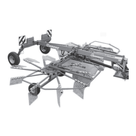
Rotary swather
Swadro 700
Swadro 800 /20
Swadro 800 /26
Swadro 900
(from Machine No. 585 170)
Table of
Contents
Previous
Page
Next
Page
1
2
3
4
5
Advertisement
Table of Contents
Need help?
Do you have a question about the Swadro 700 and is the answer not in the manual?
Ask a question
Questions and answers
Related Manuals for Krone Swadro 700
Farm Equipment Krone EASYCOLLECT 9000 Operating Instructions Manual
Maize header (52 pages)
Farm Equipment Krone EasyCollect 753 Operating Instructions Manual
Maize header (84 pages)
Farm Equipment Krone Swadro TS 620 Original Operating Instructions
Rotary rake (148 pages)
Farm Equipment Krone Swadro 807 Original Operating Instructions
Rotary swather (94 pages)
Farm Equipment Krone Swadro 35 Operating Instructions Manual
Rotary swather (38 pages)
Farm Equipment Krone Swadro TC 680 Original Operating Instructions
Rotary swather, from serial no.: 890 251 (102 pages)
Farm Equipment Krone Swadro 38 T Original Operating Instructions
Rotary swather (66 pages)
Farm Equipment Krone Swadro 38 T Original Operating Instructions
Rotary swather (66 pages)
Farm Equipment Krone Swadro 355 Operating Instructions Manual
(26 pages)
Farm Equipment Krone Swadro TC 880 Original Operating Instructions
Rotary swather (104 pages)
Farm Equipment Krone Swadro TC 680 Original Operating Instructions
Rotary rake (116 pages)
Farm Equipment Krone Swadro 2000 Original Operating Instructions
Rotary swather (262 pages)
Farm Equipment Krone EasyCut 280 Original Operating Instructions
Disc mower (80 pages)
Farm Equipment Krone Comprima F 155 Original Operating Instructions
(276 pages)
Farm Equipment Krone BiG Pack 1290 HDP VC Original Operating Instructions
Large square baler (404 pages)
Farm Equipment Krone Bellima F 125 Operating Instructions Manual
Round baler (124 pages)
This manual is also suitable for:
Swadro 800/20
Swadro 800/26
Swadro 900
Table of Contents
Print
Rename the bookmark
Delete bookmark?
Delete from my manuals?
Login
Sign In
OR
Sign in with Facebook
Sign in with Google
Upload manual
Upload from disk
Upload from URL


Need help?
Do you have a question about the Swadro 700 and is the answer not in the manual?
Questions and answers