
Related Manuals for Krone Swadro 2000


Summary of Contents for Krone Swadro 2000
- Page 1 Rotary Swather Swadro 2000 (from serial no.: 845 530) Order no.: 150 000 115 02 en 20.02.2012...
-
Page 2: Table Of Contents
Table of Contents Pos : 1 /BA/Konfor mitäts er kl ärungen/Sc hwader/N eu ab 2010/Swadro 2000 @ 39\mod_1268811690211_78.doc @ 361972 @ @ 1 EC Declaration of Conformity Maschinenfabrik Bernard Krone GmbH Heinrich-Krone-Str. 10, D-48480 Spelle hereby declare as manufacturer of the product named below, on our sole responsibility,... -
Page 3: Table Of Contents
Table of Contents Pos : 4 /Ü berschriften/Ü bers chriften 1/F-J/Inhal ts verzeic hnis @ 31\mod_1251969952727_78.doc @ 302165 @ 1 @ 1 Table of Contents Pos : 5 /BA/Inhalts verz eichnis Spr ac henneutr al @ 10\mod_1221574899104_0.doc @ 135495 @ @ 1 Table of Contents ...........................3 Foreword ...............................10 Introduction............................11... - Page 4 Mounting onto the Tractor........................ 33 PTO shaft............................34 5.7.1 Length adjustment ........................34 Height of tractor lower suspension arms ..................34 KRONE operation terminal Gamma....................35 Mounting the control unit ......................... 36 6.1.1 Electrical power supply ........................ 37 Overview ............................38 Description of the keys ........................
- Page 5 Table of Contents 6.10 Menu Level ............................59 6.10.1 Short overview ......................... 59 6.10.2 Bringing up a Menu Level ......................60 6.11 Main menu 1 - Settings........................62 6.11.1 Menu 1-2 "Zero Calibration Rotor Height" (Rotor Height Display Option)....... 63 6.11.1.1 Menu 1-3 "Overlap"......................
- Page 6 Adjust the front working width....................110 Alarm messages ..........................110 7.10 Malfunctions - Causes and Remedies................... 110 KRONE ISOBUS-Terminal CCI 100 ....................111 Installing the terminal into cabin ....................112 ISOBUS short cut button ....................... 113 8.2.1 Connecting the terminal (on tractors with integrated ISOBUS system)........115 8.2.2...
- Page 7 Attaching the ISOBUS terminal ..................... 174 9.1.1 Connection terminal to tractor....................174 9.1.2 Connection tractor to machine....................174 Differing functions to KRONE ISOBUS terminal CCI ..............175 9.2.1 Menu 4-7 “Diagnostics Auxiliary (AUX)” ..................176 Main menu 9 "ISO settings info" ....................177 9.3.1 Menu 9-1 "Softkeys ISO terminal"...
- Page 8 Table of Contents 10.2.1 Special Safety Instructions ....................184 10.2.2 Connecting the hydraulic lines....................185 10.3 Lighting connection........................186 10.4 Connecting the electrical controls....................187 10.5 Compressed Air Connections for the Compressed Air Brake ............188 10.5.1 Moving the machine without tractor ..................189 10.6 Hydraulic brake (Export) ........................
- Page 9 Table of Contents 14.8.1.2 Namur sensor d = 30 mm ....................214 Maintenance - hydraulic system .......................215 15.1 Load-sensing connection....................... 216 15.2 Adjusting the hydraulic system ...................... 217 15.3 Emergency manual activation ....................... 217 15.4 Preparing the machine for road travel (in emergency manual mode) ........... 219 15.4.1 Parallel offset .........................
-
Page 10: Foreword
Pos : 7.2 /BA/Vor wort/Sc hwader/Ver ehrter Kunde Sc hwader @ 1\mod_1202129116819_78.doc @ 57456 @ @ 1 Dear Customer, By purchasing your rotary rake, you have acquired a quality product from KRONE. We are grateful for the confidence you have invested in us in buying this machine. -
Page 11: Introduction
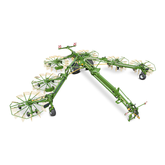
It is towed behind agricultural tractors of sufficient power that are also equipped with suitable interfaces for the installation and operation of the machine. The Swadro 2000 is a towed machine and is therefore equipped with its own running gear. The total of 6 rotors are attached to folding outrigger arms. -
Page 12: Information Required For Questions And Orders
Authentic KRONE spare parts and accessories authorised by the manufacturer help to ensure safety. The use of spare parts, accessories and other devices which are not manufactured, tested or approved by KRONE will result in the revoking of the liability for damages resulting thereof. -
Page 13: Intended Use
Introduction Pos : 9.12.1 /Übersc hriften/Übersc hriften 2/A-E/Besti mmungsgemäß er Gebrauch @ 0\mod_1196401545090_78.doc @ 7728 @ 2 @ 1 Intended Use Pos : 9.12.2 /BA/Einl eitung/Bes ti mmungsgemäßer Gebrauc h/Sc hwader /Besti mmungsgemäß er Gebr auch Sc hwader @ 1\mod_1202215704310_78.doc @ 57818 @ @ 1 The rotary rake is built exclusively for conventionaluse in agricultural work (intended use). -
Page 14: Machine Overview
Introduction Pos : 9.17 /Übersc hriften/Übersc hriften 2/K-O/Mas chi nenübersicht @ 0\mod_1195565731130_78.doc @ 555 @ 2 @ 1 Machine overview Pos : 9.18 /BA/Einl eitung/M asc hinenübersic ht/Sc hwader/M aschi nenübersic ht SW 2000 @ 39\mod_1267534448137_78.doc @ 355950 @ @ 1 SW2000067 Fig. -
Page 15: Technical Data
We reserve the right to make design changes at any time and without notification of reasons. Pos : 9.21 /BA/Einl eitung/T ec hnis che D aten/Sc hwader/Swadro 2000 @ 61\mod_1298885624861_78.doc @ 567686 @ @ 1 Type... -
Page 16: Safety
Safety Pos : 11.1 /Übersc hriften/Übersc hriften 1/P-T/Sicherheit @ 0\mod_1195566748646_78.doc @ 635 @ 1 @ 1 Safety Pos : 11.2 /BA/Sicher heit/Kennz eic hnung von Hi nweis en in der Betriebsanlei tung Ei nführ ungstext @ 0\mod_1195637804826_78.doc @ 1098 @ 2 @ 1 Identifying Symbols in the Operating Instructions The safety instructions contained in this manual which could result in personal injury if not followed are identified by the general danger sign:... -
Page 17: Personnel Qualification And Training Fehler! Textmarke Nicht Definiert
Safety Pos : 11.6 /BA/Sicher heit/Personalqualifi kati on und-Sc hul ung @ 0\mod_1195639383185_78.doc @ 1136 @ 3 @ 1 4.2.1 Personnel Qualification and Training Fehler! Textmarke nicht definiert. The machine may be used, maintained and repaired only by persons who are familiar with it and have been instructed about the dangers connected with it. -
Page 18: Safety Instructions And Accident Prevention Regulations
Safety Pos : 11.10 /BA/Sic herheit/Sicher heits- und Unfall verhütungs- Vorsc hriften Swadro_Ladewagen_Eas yC ut @ 73\mod_1308298589597_78.doc @ 655493 @ 2 @ 1 Safety Instructions and Accident Prevention Regulations Please follow all generally applicable safety and accident prevention regulations in addition to the safety instructions contained in these operating instructions! The attached warning and safety signs provide important information for safe operation. -
Page 19: Hitched Implements
Safety Parts operated by external power (e.g. hydraulically) can cause crushing and shearing injuries! Before leaving the tractor, lower the implement onto the ground, apply the parking brake, switch off the engine and remove the ignition key! Pos : 11.11 /BA/Sic herheit/Ang ehängte Geräte/Ger äte ang ehängt @ 0\mod_1199699679381_78.doc @ 33245 @ 2 @ 1 Hitched Implements 1... -
Page 20: Pto Operation
Safety Pos : 11.13 /BA/Sic herheit/Z apfwellenbetrieb Tr aktor @ 0\mod_1199699899350_78.doc @ 33264 @ 2 @ 1 PTO operation 1 Use only PTO shafts specified by the manufacturer! 2 The guard tube and guard cone of the PTO shaft and the PTO guard must be attached and in good working condition (on the implement side, too)! 3... -
Page 21: Hydraulic System
8 Replacement parts must at least comply with the technical requirements set by the manufacturer of the implements! This is guaranteed by original KRONE spare parts! Pos : 11.20 /BA/-----Seitenumbruc h------ @ 0\mod_1196175311226_0.doc @ 4165 @ @ 1... -
Page 22: Unauthorised Conversion/Modification And Spare Parts Production
Safety Pos : 11.21 /BA/Sic herheit/Eigenmäc htiger U mbau und Ers atz teil hers tell ung @ 1\mod_1201937705539_78.doc @ 55745 @ 2 @ 1 Unauthorised Conversion/Modification and Spare Parts Production Conversions or modifications of the machine are permitted only with prior consultation with the manufacturer. -
Page 23: Position Of The Adhesive Safety Stickers On The Machine
Safety Pos : 11.24 /Ü berschriften/Ü berschriften 2/K-O/Lage der Sic her hei tsaufkl eber an der M asc hine @ 0\mod_1195634967326_78.doc @ 1020 @ 2 @ 1 4.11 Position of the Adhesive Safety Stickers on the Machine Pos : 11.25 /BA/Sic herheit/Beschädigte oder unles bare Aufkleber @ 0\mod_1195567214115_78.doc @ 674 @ @ 1 Danger! - Danger zone of the machine Effect: Danger to life or serious injuries. - Page 24 Safety Pos : 11.29 /BA/Sic herheit/Aufkleber/Sc hwader/Sicherheits aufkl eber Schwader 2000 @ 61\mod_1298389016782_78.doc @ 566179 @ @ 1 SW2000021_1 Fig. 3 LH = left-hand side of the machine RH = right-hand side of the machine...
- Page 25 Safety Before starting the machine, The PTO speeds must not exceed 540 read and observe the rpm! The operating pressure of the operating instructions and hydraulic system must not exceed 200 safety instructions. bar! Order no. 939 471-1 (1x) 939 100-4 540/ MAX.
-
Page 26: Position Of The General Information Labels On The Machine
Safety Pos : 11.31 /Ü berschriften/Ü berschriften 2/K-O/Lage der allgemeinen Hinweisaufkl eber an der M asc hine @ 0\mod_1195635067920_78.doc @ 1039 @ 2 @ 1 4.14 Position of the General Information Labels on the Machine Pos : 11.32 /BA/Sic herheit/Aufkleber/Sc hwader/Hi nweis aufkl eber Schwader 2000 @ 99\mod_1329920708004_78.doc @ 885730 @ @ 1 Fig. - Page 27 Safety 1.8 bar 3.1) 1.1) 27 002 188 0 (1x) 90 mm 942 295 0 (1x) 90 mm 942 432 0 (24x) 1.8 bar 1.2) 27 002 156 0 (2x) 140 mm 3.2) 939 170 1 (2x) 2.0 bar 1.3) 27 002 157 0 (2x) 253 mm 942 301 0 (2x) 140 mm 441 071 2 (2x) 3.0 bar 3.3)
-
Page 28: Re-Ordering The Adhesive Safety And Information Labels
Pos : 11.35 /Ü berschriften/Ü berschriften 3/A-E/Anspr ec hpartner @ 0\mod_1195569394286_78.doc @ 839 @ 3 @ 1 4.14.3 Contact Pos : 11.36 /Adress en/Adr ess e Maschi nenfabri k KR ONE Spelle @ 0\mod_1195568531083_78.doc @ 734 @ @ 1 Maschinenfabrik Bernard Krone GmbH Heinrich-Krone-Strasse 10 D-48480 Spelle (Germany) Telephone: + 49 (0) 59 77/935-0 (Head Office) Fax.: + 49 (0) 59 77/935-339 (Head Office) -
Page 29: Commissioning
Commissioning Pos : 14.1 /Übersc hriften/Übersc hriften 1/A-E/Ers tinbetriebnahme @ 0\mod_1196314201498_78.doc @ 5855 @ 1 @ 1 Commissioning Pos : 14.2 /BA/Sicher heit/Gefahr enhinweis e/F ehl erhafter Z us ammenbau @ 1\mod_1202224212591_78.doc @ 58171 @ @ 1 Danger! - Incorrect assembly Effect: Danger to life, serious injuries or serious damage to the machine. -
Page 30: Fitting The Protective Frames/Hoop Guards On The 6 Rotors
Commissioning Pos : 14.8 /BA/Ersti nbetriebnahme/Schwader/Swadro 2000/Montage der Sc hutz büg els an den Kr eisel @ 61\mod_1299240759998_78.doc @ 571225 @ 2 @ 1 Fitting the Protective Frames/Hoop Guards on the 6 Rotors Before the machine can be used, all protective frames and hoop guards must be fitted on the 6 rotors. - Page 31 • Tighten tine arms exterting a torque of 105 Nm on washers (4,6) and nuts (7). Pos : 14.11 /BA/Ers tinbetriebnahme/Sc hwader/Swadro 2000/Hi nweis Zinkenar me gleic hz eitig monti eren @ 38\mod_1266477168187_78.doc @ 352641 @ @ 1 Note In order to fit the rotor arms for the rear rotor, the last two tine arms must be mounted at the same time.
-
Page 32: Requirements On The Tractor
Commissioning Pos : 14.13 /BA/Inbetri ebnahme/Schwader/Hi nweis M aschi ne befindet sic h in Trans portstellung @ 2\mod_1202388231928_78.doc @ 59050 @ @ 1 Note The description below assumes that the swather is in transport position, following final assembly. Pos : 14.14 /BA/Ers tinbetriebnahme/Sc hwader/Allgemeine Vorraussetzung am Traktor (Kat. II und III) @ 21\mod_1239191440533_78.doc @ 231556 @ 2 @ 1 Requirements on the tractor The swather features a locating drawbar for the three-point linkage (Cat. -
Page 33: Electrical Power Supply
Commissioning Pos : 14.17 /Ü berschriften/Ü berschriften 2/P-T/Spannungs versorgung @ 28\mod_1250578107003_78.doc @ 275490 @ 2 @ 1 Electrical power supply Pos : 14.18 /BA/Ers tinbetriebnahme/Spannungs vers orgung/Dauerstroms tec kdos e Bild @ 36\mod_1260454934575_78.doc @ 336632 @ @ 1 SW2000058 Fig. 8 Pos : 14.19 /BA/Ers tinbetriebnahme/Spannungs vers orgung/Stec kdos e an di e 12V Batteri e des Sc hl eppers ansc hließ... -
Page 34: Pto Shaft
Commissioning Pos : 14.23.1 /Ü berschriften/Ü berschriften 2/F-J/Gelenkwell e @ 0\mod_1199781879794_78.doc @ 34542 @ 2 @ 1 PTO shaft Pos : 14.23.2 /Ü berschriften/Ü berschriften 3/K-O/Längenanpass ung @ 1\mod_1201687632810_78.doc @ 53589 @ 3 @ 1 5.7.1 Length adjustment Pos : 14.23.3 /BA/Ers tinbetriebnahme/Gelenkwell e/Schwader/Läng enanpass ung Bild Sc hwader @ 2\mod_1202364902991_78.doc @ 58848 @ @ 1 SW9070007 Fig. -
Page 35: Krone Operation Terminal Gamma
KRONE operation terminal Gamma Pos : 16.1 /Übersc hriften/Übersc hriften 1/K-O/KR ONE Bedi enter mi nal Gamma @ 47\mod_1285222236593_78.doc @ 455915 @ 1 @ 1 KRONE operation terminal Gamma Pos : 16.2 /BA/Sicher heit/Gefahr enhinweis e/Bedieneinhei t sc hütz en @ 0\mod_1200308247867_78.doc @ 39598 @ @ 1 Caution! - Protect Control Unit. -
Page 36: Mounting The Control Unit
KRONE operation terminal Gamma Pos : 16.3.3 /BA/Info-C enter/Ladewag en/Anbau @ 36\mod_1260362759020_78.doc @ 336453 @ 2 @ 1 Mounting the control unit Fig. 13 Direct fastening • Fasten the retainer (1) using the drill holes (2) already present. The control unit (3) is fixed by the magnetic plate (4) on the retainer (1). -
Page 37: Electrical Power Supply
KRONE operation terminal Gamma Pos : 16.3.6 /Übersc hriften/Übersc hriften 3/P-T/Spannungs vers orgung @ 6\mod_1215061768540_78.doc @ 98174 @ 3 @ 1 6.1.1 Electrical power supply Pos : 16.3.7 /BA/Sicherheit/Gefahr enhinweis e/Aus fall der Bedienei nheit @ 6\mod_1215061997306_78.doc @ 98196 @ @ 1 Danger! - Failure of control unit Effect: Danger to life, injuries or damage to the machine. -
Page 38: Overview
KRONE operation terminal Gamma Overview Figure 15: 1• On/Off key 2• Display 3• Keys (1 - 8) 4 Rotary potentiometer 5. Esc key (F) 6. Menu key (E) 7. Keys A-D Pos : 16.4.2 /BA/-----Seitenumbruc h------ @ 0\mod_1196175311226_0.doc @ 4165 @ @ 1... -
Page 39: Description Of The Keys
KRONE operation terminal Gamma Pos : 16.4.3 /Übersc hriften/Übersc hriften 2/A-E/Besc hrei bung der T asten @ 6\mod_1215069821134_78.doc @ 98445 @ 2 @ 1 Description of the keys Pos : 16.4.4 /BA/Info-C enter/Sc hwader /Bedi enei nheit - Komfort/Besc hr eibung der Tas ten 1-8 Bil d SW 2000 @ 22\mod_1240206403615_78.doc @ 235411 @ @ 1... - Page 40 KRONE operation terminal Gamma Pos : 16.4.7 /BA/Info-C enter/Sc hwader /Bedi enei nheit - Komfort/Besc hr eibung der Tas ten A-F Bild SW 2000 @ 22\mod_1240206946099_78.doc @ 235462 @ @ 1 STOP SW2000028 Fig. 17 Pos : 16.4.8 /BA/Info-C enter/Beschr eibung der T asten A-F @ 6\mod_1215069984165_78.doc @ 98485 @ @ 1 Keys A-D The keys A-D are used to activate the softkeys located in the line just above them.
-
Page 41: Operational Readiness
KRONE operation terminal Gamma Pos : 16.4.10 /BA/Info-Center/Schwader/Bedi eneinheit - Komfort/Ei nsc halten Bedieneinheit SW 1400 @ 88\mod_1321358348915_78.doc @ 752705 @ 2 @ 1 Operational Readiness Switching ON Fig. 18 • Press the key. After you have switched the unit on, the connection to the job computer is established. If it is not possible to set up a connection, data connection is interrupted and the message shown on the right appears in the display. -
Page 42: Display Areas On The Screen
KRONE operation terminal Gamma Pos : 16.6.1 /BA/Info-C enter/Sc hwader /Bedi enei nheit - Komfort/SW 2000/Anz eigebereic he i m Dis play SW 2000 @ 22\mod_1240207284458_78.doc @ 235513 @ 2 @ 1 Display Areas on the Screen 12.5 15,1m 1,8m... - Page 43 KRONE operation terminal Gamma Self steer switched on (active) Auxiliary control active Auxiliary control inactive Operating hours counter deactivated Operating hours counter activated Pos : 16.6.4 /BA/-----Seitenumbruc h------ @ 0\mod_1196175311226_0.doc @ 4165 @ @ 1...
-
Page 44: Displays In The Main Window (Ii)
KRONE operation terminal Gamma Pos : 16.6.5 /BA/Info-C enter/Sc hwader /Bedi enei nheit - Komfort/SW 2000/Anz eigen im Hauptfenster (II) SW 2000 @ 90\mod_1323100442613_78.doc @ 768303 @ 3 @ 1 6.5.2 Displays in the main window (II) 12.5 15,1m 1,8m... -
Page 45: Softkeys Area (Iii)
KRONE operation terminal Gamma Pos : 16.6.7 /BA/Info-C enter/Sc hwader /Bedi enei nheit - Komfort/SW 2000/Softkeys Bereic h (III) SW 2000 @ 22\mod_1240211883286_78.doc @ 235757 @ 3 @ 1 6.5.3 Softkeys area (III) 12.5 15,1m 1,8m STOP SW2000031 Figure. 22 Pressing the key under the softkey brings up the basic screen "Lifting... -
Page 46: Softkeys Area (Iv)
KRONE operation terminal Gamma Pos : 16.6.9 /BA/Info-C enter/Sc hwader /Bedi enei nheit - Komfort/SW 2000/Softkeys Bereic h (IV) SW 2000 @ 22\mod_1240213045568_78.doc @ 235782 @ 3 @ 1 6.5.4 Softkeys area (IV) 12.5 15,1m 1,8m STOP SW2000032 Fig.23 The following functions can be performed on all 3 basic screen pages :... - Page 47 KRONE operation terminal Gamma Pos : 16.6.12 /BA/Info-Center/Schwader/Bedi eneinheit - Komfort/Swadr o 1400/Anz eigenbereic he Dis play/Gr undbil d „Br eitenverstellung“ @ 9\mod_1221037416184_78.doc @ 131406 @ @ 1 Basic screen "Width distributions" Pos : 16.6.13 /BA/Info-Center/Schwader/Bedi eneinheit - Komfort/SW 2000/Grundbild Ar beitsbr eite SW 2000 @ 22\mod_1240214438208_78.doc @ 235911 @ @ 1...
-
Page 48: Road Travel" Basic Screen
KRONE operation terminal Gamma Pos : 16.8.1 /BA/Info-C enter/Sc hwader /Bedi enei nheit - Komfort/Swadro 1400/Anzeigenber eiche Dis pl ay/Gr undbild Str aßenfahrt @ 87\mod_1320930348944_78.doc @ 748506 @ 2 @ 1 "Road Travel" Basic Screen SW1400 146_2 Fig. 24 When the control unit has been switched on, the "Road travel" basic screen is displayed. -
Page 49: Basic Screen "Lifting The Rotors
KRONE operation terminal Gamma Pos : 16.8.3 /BA/Info-C enter/Sc hwader /Bedi enei nheit - Komfort/Swadro 1400/Grundbild 1/4 Kr eisel aushebung/Übersc hrift Grundbild „Kreis el aus hebung“ @ 9\mod_1221027482903_78.doc @ 131068 @ 2 @ 1 Basic screen "Lifting the rotors" Pos : 16.8.4 /BA/Info-C enter/Sc hwader /Bedi enei nheit - Komfort/Gefahr Sc hnells top durc h EIN/AU S T aste @ 36\mod_1263276960200_78.doc @ 338506 @ @ 1 DANGER! –... -
Page 50: Lowering The Rotors From The Headland Position To The Working Position
KRONE operation terminal Gamma Pos : 16.8.11 /Ü berschriften/Ü berschriften 3/A-E/Absenken der Kreis el von Vorgewens estellung- in Arbeits stell ung @ 23\mod_1240228540083_78.doc @ 236551 @ 3 @ 1 6.7.2 Lowering the Rotors from the Headland Position to the Working Position Pos : 16.8.12 /BA/Info-Center/Schwader/Bedi eneinheit - Komfort/Gefahr Sc hnellstop durc h EIN/AUS Tas te @ 36\mod_1263276960200_78.doc @ 338506 @ @ 1... -
Page 51: Adjusting The Automatic Time
KRONE operation terminal Gamma 6.7.3.3 Adjusting the Automatic Time <Lower Rotors> 12.5 15,1m -0,0 1,8m STOP SW2000073 Fig. 27 Time delay for lowering middle rotor (1) Time delay for lowering rear rotor (2) The set time (time delay) always relates to between the rotors (front / middle or middle / rear). -
Page 52: Raising The Rotors To Headland Position
KRONE operation terminal Gamma Pos : 16.8.19 /BA/Info-Center/Schwader/Bedi eneinheit - Komfort/Swadr o 1400/Gr undbild 1/4 Kreis elaus hebung/Ü berschrift Anheben der Kreis el in di e Vorgewendestellung @ 6\mod_1215148823920_78.doc @ 99735 @ 3 @ 1 6.7.4 Raising the Rotors to Headland Position Pos : 16.8.20 /BA/Info-Center/Schwader/Bedi eneinheit - Komfort/Gefahr Sc hnellstop durc h EIN/AUS Tas te @ 36\mod_1263276960200_78.doc @ 338506 @ @ 1... -
Page 53: Raising All Rotors From The Headland Position To The Transport Position
KRONE operation terminal Gamma Pos : 16.8.25 /Ü berschriften/Ü berschriften 3/A-E/Anheben aller Kreis el von Vorgewendes tell ung- i n Trans por tstellung @ 38\mod_1267427704146_78.doc @ 355171 @ 3 @ 1 6.7.5 Raising All Rotors from the Headland Position to the Transport Position Pos : 16.8.26 /BA/Info-Center/Schwader/Bedi eneinheit - Komfort/SW 2000/Grundbild 1 Kr eisel aus hebung/Hinweis Währ end des Ei nfahrens der Arbeistbrei tenz ylinders vorahren @ 38\mod_1267428342240_78.doc @ 355243 @ @ 1... -
Page 54: Basic Screen "Width Adjustments
KRONE operation terminal Gamma Pos : 16.10.1 /BA/Info-Center/Schwader/Bedi eneinheit - Komfort/Swadr o 1400/Gr undbild 2/4 Breitenverstell ung en/Übersc hrift Grundbild „Brei tenverstell ung en“ @ 9\mod_1221028124965_78.doc @ 131112 @ 2 @ 1 Basic screen "Width adjustments" Pos : 16.10.2 /Ü berschriften/Ü berschriften 3/A-E/Arbeits breite @ 10\mod_1221198093573_78.doc @ 132335 @ 3 @ 1 6.8.1... -
Page 55: Swath Width
KRONE operation terminal Gamma Pos : 16.12.1 /Ü berschriften/Ü berschriften 3/P-T/Schwadbrei te @ 10\mod_1221198255823_78.doc @ 132357 @ 3 @ 1 6.8.3 Swath width Pos : 16.12.2 /BA/Info-Center/Schwader/Bedi eneinheit - Komfort/Gefahr Sc hnellstop durc h EIN/AUS Tas te @ 36\mod_1263276960200_78.doc @ 338506 @ @ 1 DANGER! –... -
Page 56: Raise/Lower Rotors In Pairs
KRONE operation terminal Gamma Pos : 16.14 /Ü berschriften/Ü berschriften 3/K-O/Kreis el paar weis e heben/s enken @ 90\mod_1323254335779_78.doc @ 770128 @ 3 @ 1 6.8.5 Raise/lower rotors in pairs Pos : 16.15 /BA/Info-Center/Schwader/Bedi eneinheit - Komfort/SW 2000/Grundbild 2 Br eitenverstellungen/Gr undbild „ Arbeits breite / Schwadbrei te " Bil d SW 2000 @ 23\mod_1240232410083_78.doc @ 236702 @ @ 1 12.5... -
Page 57: Basic Screen "Working Height
KRONE operation terminal Gamma Pos : 16.19.1 /BA/Info-Center/Schwader/Bedi eneinheit - Komfort/Swadr o 1400/Gr undbild 4/4 Arbeits höhe/Ü bersc hrift Gr undbil d „Ar bei thöhe“ @ 9\mod_1221028453903_78.doc @ 131178 @ 2 @ 1 Basic screen "Working height" Pos : 16.19.2 /BA/Info-Center/Schwader/Bedi eneinheit - Komfort/Gefahr Sc hnellstop durc h EIN/AUS Tas te @ 36\mod_1263276960200_78.doc @ 338506 @ @ 1 DANGER! –... -
Page 58: Rotor Height Automatic Mode
KRONE operation terminal Gamma Pos : 16.21 /BA/Info-Center/Schwader/Bedi eneinheit - Komfort/SW 2000/Grundbild 3 Ar beitshöhe/Kreis elhöhenautomati k SW 2000 @ 23\mod_1240239305990_78.doc @ 237034 @ 3 @ 1 6.9.2 Rotor height automatic mode 12.5 12.5 15,1m 15,1m 1,8m 1,8m STOP STOP SW2000037 Fig. -
Page 59: Menu Level
KRONE operation terminal Gamma Pos : 16.24.1 /Ü berschriften/Ü berschriften 2/K-O/M enüebene Kurzüberblic k @ 33\mod_1255074316915_78.doc @ 321525 @ 23 @ 1 6.10 Menu Level 6.10.1 Short overview Pos : 16.24.2 /BA/Info-Center/Schwader/Bedi eneinheit - Komfort/SW 2000/H auptmenüs /Menüebene Kurz überblic k SW 2000 @ 90\mod_1323160424851_78.doc @ 769121 @ @ 1 Fig. -
Page 60: Bringing Up A Menu Level
KRONE operation terminal Gamma Pos : 16.24.4 /BA/Info-Center/Ladewagen/M enüebene aufr ufen @ 0\mod_1200656618584_78.doc @ 46496 @ 3 @ 1 6.10.2 Bringing up a Menu Level Fig. 35 Press the (1) key. The menu level is shown in the display. You can exit the menu level again with the (2) key. - Page 61 KRONE operation terminal Gamma Pos : 16.24.6 /BA/Info-Center/Schwader/Bedi eneinheit - Komfort/SW 2000/H auptmenüs /Hauptmenü 1 Eins ellungen/M enüebene Ü berblic k H auptmenüs @ 61\mod_1298902412283_78.doc @ 568136 @ @ 1 The menu level is divided into six main menus: SW2000039_2 Fig.
-
Page 62: Main Menu 1 - Settings
KRONE operation terminal Gamma Pos : 16.24.8 /BA/Info-Center/Schwader/Bedi eneinheit - Komfort/SW 2000/H auptmenüs /Hauptmenü 1 Eins ellungen/H auptmenü „Ei nstellungen“ @ 90\mod_1323161052076_78.doc @ 769177 @ 2 @ 1 6.11 Main menu 1 - Settings SW2000039_2 Fig. 37 • to call the menu level. -
Page 63: Menu 1-2 "Zero Calibration Rotor Height" (Rotor Height Display Option)
KRONE operation terminal Gamma Pos : 16.24.10 /BA/Info-C enter/Sc hwader/Bedienei nheit - Komfort/SW 2000/Hauptmenüs/H auptmenü 1 Ei ns ellung en/Menü 1- 2 „N ullabgleich Kr eisel höhe“ (Option Kreis elhöhenanz eige) SW 2000 @ 90\mod_1323169827156_78.doc @ 769296 @ 3 @ 1 6.11.1 Menu 1-2 "Zero Calibration Rotor Height"... -
Page 64: Menu 1-3 "Overlap
KRONE operation terminal Gamma Pos : 16.24.12 /BA/Info-C enter/Sc hwader/Bedienei nheit - Komfort/SW 2000/Hauptmenüs/H auptmenü 1 Ei ns ellung en/Menü 1- 3 Ü berl appung @ 90\mod_1323184501134_78.doc @ 769758 @ 4 @ 1 6.11.1.1 Menu 1-3 "Overlap" 1 - 3... -
Page 65: Menu 1-4 „Unit Of Measurement
KRONE operation terminal Gamma Pos : 16.24.14 /BA/Info-C enter/Sc hwader/Bedienei nheit - Komfort/SW 2000/Hauptmenüs/H auptmenü 1 Ei ns ellung en/Menü 1- 4 „M ass einheit“ @ 90\mod_1323175091364_78.doc @ 769435 @ 3 @ 1 6.11.2 Menu 1-4 „Unit of measurement“ 1 - 4 SW2000081 Fig. -
Page 66: Menu 1-5 "Contrast
KRONE operation terminal Gamma Pos : 16.24.16 /BA/Info-C enter/Sc hwader/Bedienei nheit - Komfort/SW 2000/Hauptmenüs/H auptmenü 1 Ei ns ellung en/Menü 1- 5 Kontras t 1/2 Übersc hrift/Bild @ 90\mod_1323178382734_78.doc @ 769496 @ 3 @ 1 6.11.3 Menu 1-5 "Contrast" 1 - 5 SW2000082 Fig. - Page 67 KRONE operation terminal Gamma Pos : 16.24.19 /BA/Info-C enter/Sc hwader/Bedienei nheit - Komfort/SW 2000/Hauptmenüs/H auptmenü 1 Ei ns ellung en/Menü 1- 5 Kontr ast 2/2 @ 90\mod_1323178497739_78.doc @ 769612 @ @ 1 Day/night design 1 - 5 1 - 5...
-
Page 68: Main Menu 2 - Counters
KRONE operation terminal Gamma Pos : 16.24.21 /BA/Info-C enter/Sc hwader/Bedienei nheit - Komfort/SW 2000/Hauptmenüs/H auptmenü 2 Zähl er/Hauptmenü 2 Z ähl er @ 61\mod_1298903223121_78.doc @ 568248 @ 2 @ 1 6.12 Main menu 2 – Counters SW2000041_2 Fig. 43 Calling the main menu •... - Page 69 KRONE operation terminal Gamma Pos : 16.24.23 /BA/Info-C enter/Sc hwader/Bedienei nheit - Komfort/SW 2000/Hauptmenüs/H auptmenü 2 Zähl er/Kundenz ähler akti vi eren SW 2000 @ 23\mod_1240311796350_78.doc @ 237790 @ @ 1 Activating customer counter 12,1 126,1 423,5 402,2 206,8 1023,1...
- Page 70 KRONE operation terminal Gamma Pos : 16.24.25 /BA/Info-C enter/Sc hwader/Bedienei nheit - Komfort/SW 2000/Hauptmenüs/H auptmenü 2 Zähl er/Kundenz ähler l ösc hen SW 2000 @ 23\mod_1240312708506_78.doc @ 237865 @ @ 1 Deleting the customer counter 12,1 126,1 423,5 402,2 206,8...
-
Page 71: Menu 2-2 "Total Counters
KRONE operation terminal Gamma Pos : 16.24.27 /BA/Info-C enter/Sc hwader/Bedienei nheit - Komfort/SW 2000/Hauptmenüs/H auptmenü 2 Zähl er/Menü 2- 2 Ges amtz ähler SW 2000 @ 90\mod_1323260199778_78.doc @ 770156 @ 3 @ 1 6.12.1 Menu 2-2 "Total counters" 36,1 20,3... -
Page 72: Main Menu 3 „Manual Operation
KRONE operation terminal Gamma Pos : 16.24.29.1 /Ü bersc hriften/Ü bersc hriften 2/F-J/H auptmenü 3 H andbedi enung @ 55\mod_1292224852765_78.doc @ 517684 @ 2 @ 1 6.13 Main menu 3 „Manual operation“ Pos : 16.24.29.2 /BA/Info-C enter/Sc hwader/Bedienei nheit - Komfort/SW 2000/Hauptmenüs/H auptmenü 3 Wartung / H andbetrieb/War nung H andbetri eb @ 23\mod_1240323600491_78.doc @ 238645 @ @ 1 WARNING! –... - Page 73 KRONE operation terminal Gamma Pos : 16.24.29.6 /BA/Info-C enter/Sc hwader/Bedienei nheit - Komfort/Gefahr Schnellstop durch EIN /AU S T aste @ 36\mod_1263276960200_78.doc @ 338506 @ @ 1 DANGER! – Before swivelling the machine, ensure that nobody is within the swivel range.
-
Page 74: Selecting The Rotors For A Function
KRONE operation terminal Gamma Pos : 16.24.29.1 /BA/Info-C enter/Sc hwader/Bedienei nheit - Komfort/SW 2000/Hauptmenüs/H auptmenü 3 Wartung / H andbetrieb/Handbetri eb Grundbil d 1 Kr eisel aushebung @ 23\mod_1240381994708_78.doc @ 238974 @ @ 1 Basic screen 1 "Lifting the rotors"... -
Page 75: Adjust The Front Working Width
KRONE operation terminal Gamma Pos : 16.24.29.1 /BA/Info-C enter/Sc hwader/Bedienei nheit - Komfort/SW 2000/Hauptmenüs/H auptmenü 3 Wartung / H andbetrieb/Handbetri eb Grundbil d 2 „Ar beitsbr eite / Sc hwadbreite " Bild SW 2000 @ 23\mod_1240382297114_78.doc @ 239003 @ @ 1 Basic screen 2 "Working width/swath width/parallel offset"... -
Page 76: Adjusting The Swath Width
KRONE operation terminal Gamma Pos : 16.24.29.2 /BA/Info-C enter/Sc hwader/Bedienei nheit - Komfort/SW 2000/Hauptmenüs/H auptmenü 3 Wartung / H andbetrieb/Handbetri eb Grundbil d 2 „Ar beitsbr eite / Sc hwadbreite " Bild SW 2000 @ 23\mod_1240382297114_78.doc @ 239003 @ @ 1 Basic screen 2 "Working width/swath width/parallel offset"... -
Page 77: Adjusting The Parallel Offset
KRONE operation terminal Gamma Pos : 16.24.29.2 /BA/Info-C enter/Sc hwader/Bedienei nheit - Komfort/SW 2000/Hauptmenüs/H auptmenü 3 Wartung / H andbetrieb/Handbetri eb Grundbil d 2 „Ar beitsbr eite / Sc hwadbreite " Bild SW 2000 @ 23\mod_1240382297114_78.doc @ 239003 @ @ 1 Basic screen 2 "Working width/swath width/parallel offset"... - Page 78 KRONE operation terminal Gamma Pos : 16.24.29.3 /BA/Info-C enter/Sc hwader/Bedienei nheit - Komfort/SW 2000/Hauptmenüs/H auptmenü 3 Wartung / H andbetrieb/Handbetri eb Grundbil d 3 „Tasträder / Z wangslenkung" Bil d SW 2000 @ 23\mod_1240382949176_78.doc @ 239054 @ @ 1 Basic screen 3 "Guide wheels/self steer"...
-
Page 79: Main Menu 4 - Service
KRONE operation terminal Gamma Pos : 16.24.31 /BA/Info-C enter/Sc hwader/Bedienei nheit - Komfort/SW 2000/Hauptmenüs/H auptmenü 4 Ser vice/Hauptmenü 4 Ser vic e SW 2000 @ 61\mod_1298903430761_78.doc @ 568275 @ 2 @ 1 6.14 Main menu 4 – Service SW2000043_2 Fig. 53 Calling the main menu •... -
Page 80: Menu 4-2 "Manual Sensor Test
KRONE operation terminal Gamma Pos : 16.24.33 /BA/Info-C enter/Sc hwader/Bedienei nheit - Komfort/SW 2000/Hauptmenüs/H auptmenü 4 Ser vice/Menü 4-2 Sens ortest H and SW 2000 @ 61\mod_1298904084182_78.doc @ 568386 @ 3 @ 1 6.14.1 Menu 4-2 "Manual Sensor Test" SW2000074 SW2000045 Fig. - Page 81 KRONE operation terminal Gamma Pos : 16.24.37 /BA/Info-C enter/Sens or en/M ögliche Sens oren (je nac h Aus stattung der Mas chi ne) @ 19\mod_1238071336628_78.doc @ 214010 @ @ 1 Possible sensors (depending on how the machine is equipped) Pos : 16.24.38 /BA/Info-C enter/Sc hwader/Bedienei nheit - Komfort/SW 2000/Hauptmenüs/H auptmenü 4 Ser vice/Mögliche N amursens oren Aufzählung SW 2000 @ 36\mod_1260965256355_78.doc @ 337661 @ @ 1...
- Page 82 SW2000059_1 Fig. 55 Pos : 16.24.43 /BA/Info-C enter/C C-ISOBU S-Ter minal/CC I-Swadr o/Swadro 2000/H auptmenüs/H auptmenü 4 Ser vic e/Dr ehwi nkelsens or Ar bei tsbr eite prüfen und Eins tell en @ 90\mod_1323092929618_78.doc @ 767760 @ @ 1 Note The machine must be in the transport position before you test and adjust the angle of rotation sensor.
- Page 83 KRONE operation terminal Gamma Pos : 16.24.46 /BA/Info-C enter/Sc hwader/Bedienei nheit - Komfort/SW 2000/Hauptmenüs/H auptmenü 4 Ser vice/Drehwinkels ensor maxi mal e Arbeits breite @ 90\mod_1323250105060_78.doc @ 769922 @ @ 1 Setting the maximum working width (narrow bar on right) •...
- Page 84 KRONE operation terminal Gamma Pos : 16.24.51 /BA/Info-C enter/Sc hwader/Bedienei nheit - Komfort/SW 2000/Hauptmenüs/H auptmenü 4 Ser vice/Diag nos e Vers orgungsspannung en SW 2000 @ 36\mod_1260973165480_78.doc @ 337868 @ @ 1 Diagnostics - power supply voltages SW2000046_1 Fig. 56...
-
Page 85: Actuator Test
KRONE operation terminal Gamma Pos : 16.24.53 /Ü bersc hriften/Ü bersc hriften 3/A- E/Aktortes t @ 0\mod_1200916990791_78.doc @ 47833 @ 3 @ 1 6.14.2 Actuator test Pos : 16.24.54 /BA/Sic her hei t/Gefahrenhi nweis e/Aktortest @ 47\mod_1285134152781_78.doc @ 455729 @ @ 1 Danger! - Unexpected actions on the machine. -
Page 86: Menu 4-4 "Manual Actuator Test
KRONE operation terminal Gamma Pos : 16.24.56 /BA/Info-C enter/Sc hwader/Bedienei nheit - Komfort/Swadro 1400/Hauptmenüs/H auptmenü 4 Ser vice/Menü 4- 4 Aktortest H and @ 7\mod_1215417049746_78.doc @ 101179 @ 3 @ 1 6.14.3 Menu 4-4 "Manual Actuator Test" The actuator test is used to test the actuators installed on the machine. An actuator can only be tested if power is flowing through it. - Page 87 KRONE operation terminal Gamma Pos : 16.24.58 /BA/Info-C enter/Groß pac kenpresse/Hauptmenüs/H auptmenü 4 Ser vice/Diagnos e digital e Aktoren @ 19\mod_1238420315378_78.doc @ 217898 @ @ 1 Diagnostics – digital actuators Errors are only displayed if the actuator is turned on and a test is possible for the actuator (see the table called "Possible digital actuators").
- Page 88 KRONE operation terminal Gamma Sensor Description Sensor Description icon icon Function valve 1 Raise MR rotor arm Steering 1 MR rotor arm in float position Steering 2 Raise RR rotor arm Left guide wheel RR rotor arm in float position...
- Page 89 KRONE operation terminal Gamma Pos : 16.24.63 /BA/Info-C enter/Sens or en/Status anzeigen digital e Aktoren Versi on 1 ( 1,2,3,4,5) @ 24\mod_1240835189496_78.doc @ 241140 @ @ 1 State: Actuator on Actuator off General actuator error FUSE No power supply; fuse is probably defective Possible error condition Pos : 16.24.64 /BA/-----Seitenumbr uch------ @ 0\mod_1196175311226_0.doc @ 4165 @ @ 1...
-
Page 90: Main Menu 5 - Information
KRONE operation terminal Gamma Pos : 16.24.65 /BA/Info-C enter/Sc hwader/Bedienei nheit - Komfort/SW 2000/Hauptmenüs/H auptmenü 5 Info/H auptmenü 5 Info @ 23\mod_1240318768819_78.doc @ 238413 @ 2 @ 1 6.15 Main Menu 5 – Information 00002009491 1 : 150200094-00 SW2000047 Fig. 59 Calling the main menu •... -
Page 91: Main Menu 6 "Technician
KRONE operation terminal Gamma Pos : 16.24.67 /BA/Info-C enter/Ladewagen/H auptmenüs/H auptmenü 6 Monteur/Hauptmenü 6 M onteur @ 0\mod_1200929434744_78.doc @ 48759 @ 2 @ 1 6.16 Main menu 6 "Technician" Calling the main menu Figure. 60 • Call the menu level with the key. -
Page 92: Alarm Message
KRONE operation terminal Gamma Pos : 16.24.69 /BA/Info-C enter/Sc hwader/Bedienei nheit - Komfort/SW 2000/Hauptmenüs/Alar mmeldung en/Al armel dung allgemein Bil d SW 2000 @ 23\mod_1240320584725_78.doc @ 238520 @ 3 @ 1 6.16.1 Alarm Message 12.5 15,1m 1,8m STOP SW2000048 Fig. 61 Pos : 16.24.70 /BA/Info-C enter/Sc hwader/Bedienei nheit - Komfort/SW 2000/Hauptmenüs/Alar mmeldung en/Al armel dung allgemein Text @ 23\mod_1240320564928_78.doc @ 238495 @ @ 1... -
Page 93: Alarm Messages
KRONE operation terminal Gamma Pos : 16.24.72 /BA/Info-C enter/Sc hwader/Bedienei nheit - Komfort/Swadro 1400/Al armmeldung/Allgemeine Alar mmel dung en Tabell e SW 2000 @ 36\mod_1263292130184_78.doc @ 338667 @ 23 @ 1 6.17 Alarm messages 6.17.1 General alarms No. Screen Description... -
Page 94: Logical Alarms
KRONE operation terminal Gamma Pos : 16.24.74 /BA/Info-C enter/Sc hwader/Bedienei nheit - Komfort/SW 2000/Hauptmenüs/Alar mmeldung en/Logische Alar me SW 2000 1 bis 7 @ 36\mod_1261043261440_78.doc @ 337996 @ 3 @ 1 6.17.2 Logical alarms Left guide wheel When the swather is... - Page 95 KRONE operation terminal Gamma system, supporting wheel not extended Sensors incorrectly Check sensors' adjustment, Right supporting adjusted, linkage lower supporting wheel in wheel not fully jammed, incorrectly manual mode extended connected hydraulic system, supporting wheel not extended Pos : 16.24.76 /BA/Info-C enter/Sc hwader/Bedienei nheit - Komfort/SW 2000/Hauptmenüs/Alar mmeldung en/Logische Alar me SW 2000 13 @ 61\mod_1298970052439_78.doc @ 568776 @ @ 1...
-
Page 96: Physical Alarms
KRONE operation terminal Gamma Pos : 16.24.78 /BA/Info-C enter/Sc hwader/Bedienei nheit - Komfort/SW 2000/Hauptmenüs/Alar mmeldung en/Physi kalische Alar me @ 36\mod_1261043873175_78.doc @ 338020 @ 3 @ 1 6.17.3 Physical alarms Steering activated Steering deactivated Guide wheel in transport position left... - Page 97 KRONE operation terminal Gamma Left guide wheel in working position Right guide wheel in working position Angle of right outrigger Angle of left outrigger Right guide wheel setting Left guide wheel setting Wheel sensor acreage counter Sensor or supply - Perform a sensor...
- Page 98 KRONE operation terminal Gamma Pos : 18 /BA/Di es e Seite is t bewusst freig elass en worden. @ 1\mod_1201783680373_78.doc @ 54443 @ @ 1 This page has been left blank deliberately!! Pos : 19 /BA/-----Sei tenumbruch------ @ 0\mod_1196175311226_0.doc @ 4165 @ @ 1...
-
Page 99: Control Unit - Auxiliary Control
Control Unit – Auxiliary Control Pos : 20.1 /Übersc hriften/Übersc hriften 1/A-E/Bedienei nheit - Zus taztbedienung @ 23\mod_1240387195364_78.doc @ 239205 @ 1 @ 1 Control Unit – Auxiliary Control Pos : 20.2 /BA/Sicher heit/Gefahr enhinweis e/Bedieneinhei t sc hütz en @ 0\mod_1200308247867_78.doc @ 39598 @ @ 1 Caution! - Protect Control Unit. -
Page 100: Mounting
Control Unit – Auxiliary Control Pos : 20.3.3 /BA/Info-C enter/Sc hwader /Bedi enei nheit - M edium/Anbau @ 36\mod_1260880356866_78.doc @ 337134 @ 2 @ 1 Mounting Figure. 63 • Fasten the support (1) using the drill holes (2) already present. •... -
Page 101: Electrical Power Supply
Control Unit – Auxiliary Control Pos : 20.3.6 /Übersc hriften/Übersc hriften 3/P-T/Spannungs vers orgung @ 6\mod_1215061768540_78.doc @ 98174 @ 3 @ 1 7.1.1 Electrical power supply Pos : 20.3.7 /BA/Sicherheit/Gefahr enhinweis e/Aus fall der Bedienei nheit @ 6\mod_1215061997306_78.doc @ 98196 @ @ 1 Danger! - Failure of control unit Effect: Danger to life, injuries or damage to the machine. -
Page 102: Overview Of Auxiliary Control
Control Unit – Auxiliary Control Pos : 20.5 /BA/Info-C enter/Sc hwader/Bedi enei nheit - Komfort/SW 2000/Zus atzbedi enung/Übersic ht Z us atz bedi enung SW 2000 @ 36\mod_1260875445694_78.doc @ 336930 @ 2 @ 1 Overview of Auxiliary Control SW2000053_1 Fig. 65 Pos : 20.6 /BA/-----Seitenumbruch------ @ 0\mod_1196175311226_0.doc @ 4165 @ @ 1... - Page 103 Control Unit – Auxiliary Control Pos : 20.7 /BA/Info-C enter/Sc hwader/Bedi enei nheit - Komfort/SW 2000/Zus atzbedi enung/Übersic ht Beschr eibung der T asten und Kontrolll euc hten SW 2000 @ 61\mod_1298961157233_78.doc @ 568581 @ @ 1 Keys Pilot lamps Reduce front working width Reduce the working width Increase front working width...
-
Page 104: Operational Readiness
Control Unit – Auxiliary Control Pos : 20.9 /BA/Info-C enter/Sc hwader/Bedi enei nheit - Komfort/SW 2000/Zus atzbedi enung/Betri ebs bereits chaft Zusatzbedienung SW 2000 @ 23\mod_1240392733505_78.doc @ 239620 @ 2 @ 1 Operational Readiness SW2000054 Fig. 66 The control unit (4) is only possible in combination with the control unit (3). The control unit (3) must be switched on so that power is supplied to the control unit (4)! Once the control unit (4) has been activated, all functions that can be accessed from control unit (4) are blocked in control unit (3). -
Page 105: Lowering The Rotors From Transport To Headland Position
Control Unit – Auxiliary Control Pos : 20.11 /BA/Info-Center/Schwader/Bedi eneinheit - Komfort/SW 2000/Z us atz bedi enung/Absenken Kr eisel Trans port- i n Vorrgewendestellung Bil d SW 2000 @ 36\mod_1260879255522_78.doc @ 337009 @ 2 @ 1 Lowering the Rotors from Transport to Headland Position SW2000055_1 Fig. -
Page 106: Lowering The Rotors From The Headland Position To The Working Position
Control Unit – Auxiliary Control Pos : 20.14 /BA/Info-Center/Schwader/Bedi eneinheit - Komfort/SW 2000/Z us atz bedi enung/Absenken Kr eisel Vorgewend- i n Arbeitsstellung Bil d SW 2000 @ 36\mod_1260879527881_78.doc @ 337034 @ 2 @ 1 Lowering the Rotors from the Headland Position to the Working Position SW2000056 Fig. - Page 107 Control Unit – Auxiliary Control Pos : 20.19 /BA/Diese Seite ist bewusst freigel ass en wor den. @ 1\mod_1201783680373_78.doc @ 54443 @ @ 1 This page has been left blank deliberately!! Pos : 20.20 /BA/-----Seitenumbruc h------ @ 0\mod_1196175311226_0.doc @ 4165 @ @ 1...
-
Page 108: Raising The Rotors From The Working Position To The Headland Position
Control Unit – Auxiliary Control Pos : 20.21 /BA/Info-Center/Schwader/Bedi eneinheit - Komfort/SW 2000/Z us atz bedi enung/Anheben Kreis el Ar bei ts- in Vorrgewendes tell ung Bild SW 2000 @ 36\mod_1260879620475_78.doc @ 337059 @ 2 @ 1 Raising the Rotors from the Working Position to the Headland Position SW2000056_1 Fig. -
Page 109: Raising All Rotors From The Headland Position To The Transport Position
Control Unit – Auxiliary Control Pos : 20.26 /BA/Info-Center/Schwader/Bedi eneinheit - Komfort/SW 2000/Z us atz bedi enung/Anheben aller Kreis el Vorgewende- in Trans ports tell ung SW 2000 @ 23\mod_1240403385567_78.doc @ 240042 @ 2 @ 1 Raising All Rotors from the Headland Position to the Transport Position Pressing the key raises all rotors to the transport position. -
Page 110: Adjusting The Working Width
Control Unit – Auxiliary Control Pos : 20.28 /BA/Info-Center/Schwader/Bedi eneinheit - Komfort/SW 2000/Z us atz bedi enung/Arbeits brei te ei nstellen SW 2000 @ 36\mod_1260879697022_78.doc @ 337085 @ 23 @ 1 Adjusting the Working Width SW2000056 Fig. 70 7.8.1 Adjust the front working width To increase the working width: Press the To reduce the working width:... -
Page 111: Krone Isobus-Terminal Cci 100
For mounting and repair jobs, especially for welding jobs on the machine, disconnect the power supply to the control unit. Overvoltage can damage the control unit. Pos : 22.1.4 /BA/Info-C enter/CC-ISOBU S-Ter minal/CCI- Swadro/Swadro 2000/Allgemei ne Besc hrei bung Bil d SW 2000 @ 86\mod_1320047236955_78.doc @ 740823 @ @ 1 CCS00050 CC000013 Fig. -
Page 112: Installing The Terminal Into Cabin
KRONE ISOBUS-Terminal CCI 100 Pos : 22.1.7 /Übersc hriften/Übersc hriften 2/P-T/T er minal in Kabine einbauen @ 47\mod_1285163419265_78.doc @ 455855 @ 2 @ 1 Installing the terminal into cabin Pos : 22.1.8 /BA/Info-C enter/CC-ISOBU S-Ter minal/Hinweis zu Anbau in Kabine @ 47\mod_1285163596984_78.doc @ 455881 @ @ 1... -
Page 113: Isobus Short Cut Button
KRONE ISOBUS-Terminal CCI 100 Pos : 22.1.10.1 /Ü berschriften/Ü berschriften 2/F-J/ISOBU S Short C ut Button @ 47\mod_1285564773000_78.doc @ 456410 @ 2 @ 1 ISOBUS short cut button Pos : 22.1.10.2 /BA/Info-Center/CC-ISOBUS-T ermi nal /Modul e für Bei pac k/ISOBU S Short C ut Button_2 Gefahr @ 46\mod_1282643782875_78.doc @ 447376 @ @ 1 DANGER! –... - Page 114 KRONE ISOBUS-Terminal CCI 100 If the ISOBUS short cut button is deactivated again, the following message will appear in the display of the terminal: CC000071 Fig. 74 The alarm mask is left by pressing the function key . It is only now that all functions of the machine are available again.
-
Page 115: Connecting The Terminal (On Tractors With Integrated Isobus System)
Note The connection of terminal to tractor takes place via a special cable set (5) which can be ordered by stating the KRONE article no. 20 081 223 0. • Connect plug (2) of cable set (5) with socket (1) (CAN1-IN) of the terminal •... -
Page 116: Connecting The Terminal (On Tractors Without Isobus System)
KRONE ISOBUS-Terminal CCI 100 Pos : 22.1.14 /BA/Info-Center/CC-ISOBUS-T ermi nal /CCI-Bi G Pac k/T ermi nal ansc hließ en( ohne ISO Sc hl epper) @ 43\mod_1274882231640_78.doc @ 387925 @ 3 @ 1 8.2.2 Connecting the terminal (on tractors without ISOBUS system) CC00015 Fig. -
Page 117: Connecting The Multi-Function Lever To The Cci Terminal
Note The terminal is connected to the multi-function lever via a special cable set (9) which can be ordered by stating the Krone product no. 20 081 676 0. • Connect plug (2) of cable set (9) with the socket (1) (CAN1-IN) of the terminal •... -
Page 118: Switching The Terminal On / Off When The Machine Is Not Connected
KRONE ISOBUS-Terminal CCI 100 Pos : 22.1.18 /Ü berschriften/Ü berschriften 3/A-E/Ein- Aussc hal ten des T ermi nals bei nicht ang esc hloss ener M asc hine @ 43\mod_1275290766562_78.doc @ 389835 @ 3 @ 1 8.2.4 Switching the terminal on / off when the machine is not connected Pos : 22.1.19 /BA/Info-Center/CC-ISOBUS-T ermi nal /CCI-Bi G Pac k/Ei n- Auss chalten Bil d mit nic ht ang esc hloss ener M asc hine @ 43\mod_1275291241781_78.doc @ 389860 @ @ 1... -
Page 119: Switching The Terminal On / Off When The Machine Is Connected
KRONE ISOBUS-Terminal CCI 100 Pos : 22.1.23 /Ü berschriften/Ü berschriften 3/A-E/Ein- Aussc hal ten des T ermi nals bei ang esc hloss ener M asc hi ne @ 43\mod_1274866210140_78.doc @ 387724 @ 3 @ 1 8.2.5 Switching the terminal on / off when the machine is connected Pos : 22.1.24 /BA/Info-Center/CC-ISOBUS-T ermi nal /CCI-Swadro/Swadr o 2000/Ei n- Auss chalten Bild mit ang esc hloss ener M asc hi ne SW 2000 @ 90\mod_1323098893931_78.doc @ 768216 @ @ 1... -
Page 120: Display Areas On The Screen
KRONE ISOBUS-Terminal CCI 100 Pos : 22.1.31.1 /BA/Info-Center/CC-ISOBUS-T ermi nal /CCI-Swadro/Swadr o 2000/Anz eigenbereic he Displ ay/Anzeigebereic he im Displ ay SW 2000 @ 86\mod_1320240801243_78.doc @ 742832 @ 2 @ 1 Display Areas on the Screen 19.0m 2.4m CCS00051 Fig. 81 Pos : 22.1.31.2 /BA/Info-Center/Schwader/Bedieneinhei t - Komfort/SW 2000/Hi nweis Erläuterung Gr undbild Brei tenverstell ung en @ 23\mod_1240316895944_78.doc @ 238173 @ @ 1... -
Page 121: Status Line Area (I)
KRONE ISOBUS-Terminal CCI 100 Pos : 22.1.31.4 /BA/Info-Center/CC-ISOBUS-T ermi nal /CCI-Swadro/Swadr o 2000/Anz eigenbereic he Displ ay/Statusz eile Bereic h (I) Bild @ 86\mod_1320240879351_78.doc @ 742860 @ 3 @ 1 8.3.1 Status line area (I) 19.0m 2.4m CCS00052 Fig. 82 Pos : 22.1.31.5 /BA/Info-Center/CC-ISOBUS-T ermi nal /CCI-Swadro/Swadr o 2000/Anz eigenbereic he Displ ay/Statusz eile Bereic h (I) @ 87\mod_1321276526687_78.doc @ 751765 @ @ 1... -
Page 122: Displays In The Main Window (Ii)
1 = Operating hours counter, current customer counter 1 = Surface counter Pos : 22.1.31.10 /BA/Info-C enter/CC- ISOBU S-Ter minal/CC I-Swadr o/Swadro 2000/Anzeigenber eiche Dis play/Anz eigen i m H auptfenster mögliche Status meldungen @ 90\mod_1322751766850_78.doc @ 766256 @ @ 1 Possible status messages: = Rotor in float setting;... - Page 123 Description of the symbols (III) for the function keys (F1 to F12) Pos : 22.1.31.13 /BA/Info-C enter/CC- ISOBU S-Ter minal/CC I-Swadr o/Swadro 2000/Anzeigenber eiche Dis play/F unktionstasten F 1 bis F 12 (III) Bil d @ 86\mod_1320241532923_78.doc @ 742944 @ @ 1 Fig.
- Page 124 KRONE ISOBUS-Terminal CCI 100 Pos : 22.1.31.21 /BA/Info-C enter/CC- ISOBU S-Ter minal/CC I-Swadr o/Swadro 2000/Anzeigenber eiche Dis play/F unktionstasten F 1 bis F 12 (III) Bil d @ 86\mod_1320241532923_78.doc @ 742944 @ @ 1 Fig. 85 Pos : 22.1.31.22 /BA/Info-C enter/CC- ISOBU S-Ter minal/CC I-Swadr o/Swadro 2000/Grundbild 2 Br eitenverstellungen/Arbeits breite vorne eins tell en SW 2000 @ 88\mod_1321354469608_78.doc @ 752530 @ @ 1...
-
Page 125: Basic Screen "Width Adjustments
KRONE ISOBUS-Terminal CCI 100 Pos : 22.1.33.1 /BA/Info-Center/Schwader/Bedieneinhei t - Komfort/Swadr o 1400/Gr undbild 2/4 Breitenvers tell ung en/Übersc hrift Grundbild „Breitenverstell ung en“ @ 9\mod_1221028124965_78.doc @ 131112 @ 2 @ 1 Basic screen "Width adjustments" Pos : 22.1.33.2 /BA/Info-Center/CC-ISOBUS-T ermi nal /CCI-Swadro/Swadr o 2000/Anz eigenbereic he Displ ay/F 1 Aufruf der Grundbilder @ 87\mod_1321277064622_78.doc @ 751820 @ @ 1 Calling of "Width adjustment", "Working height"... -
Page 126: Swath Width
Pos : 22.1.33.10 /BA/Info-C enter/CC- ISOBU S-Ter minal/CC I-Swadr o/Swadro 2000/Grundbild 2 Br eitenverstellungen/Gr undbild „ Arbeits breite / Schwadbr eite“ Bild @ 88\mod_1321354530499_78.doc @ 752558 @ @ 1 Fig. 87 Pos : 22.1.33.11 /BA/Info-C enter/CC- ISOBU S-Ter minal/CC I-Swadr o/Swadro 2000/Grundbild 2 Br eitenverstellungen/Schwadbr eite ei nstellen SW 2000 @ 88\mod_1321354606142_78.doc @ 752586 @ @ 1... -
Page 127: Basic Screen "Working Height
KRONE ISOBUS-Terminal CCI 100 Pos : 22.1.35.1 /BA/Info-Center/Schwader/Bedieneinhei t - Komfort/Swadr o 1400/Gr undbild 4/4 Arbeits höhe/Ü bersc hrift Gr undbil d „Ar bei thöhe“ @ 9\mod_1221028453903_78.doc @ 131178 @ 2 @ 1 Basic screen "Working height" Pos : 22.1.35.2 /BA/Info-Center/CC-ISOBUS-T ermi nal /CCI-Swadro/Swadr o 1400/Gefahr Sc hnellstop @ 56\mod_1295362873734_78.doc @ 542364 @ @ 1 DANGER! - Before swivelling the machine, ensure that nobody is within the swivel range. -
Page 128: Basic Screen „Lifting The Rotors
KRONE ISOBUS-Terminal CCI 100 Pos : 22.1.37.1 /Ü berschriften/Ü berschriften 2/F-J/Grundbild Kr eisel aushebung @ 56\mod_1295354299046_78.doc @ 541986 @ 2 @ 1 Basic Screen „Lifting The Rotors“ Pos : 22.1.37.2 /BA/Info-Center/CC-ISOBUS-T ermi nal /CCI-Swadro/Swadr o 1400/Gefahr Sc hnellstop @ 56\mod_1295362873734_78.doc @ 542364 @ @ 1 DANGER! - Before swivelling the machine, ensure that nobody is within the swivel range. -
Page 129: Lowering The Rotors From The Headland Position To The Working Position
Pos : 22.1.37.13 /BA/Info-C enter/CC- ISOBU S-Ter minal/CC I-Swadr o/Swadro 2000/Grundbild 1 Kr eisel aushebung/Abs enken aller Kreis el in di e Arbeitss tell ung Automati kbetrieb SW 2000 @ 88\mod_1321434093011_78.doc @ 753686 @ 4 @ 1 8.6.2.3... -
Page 130: Adjusting The Automatic Time
KRONE ISOBUS-Terminal CCI 100 Pos : 22.1.37.15 /BA/Info-C enter/CC- ISOBU S-Ter minal/CC I-Swadr o/Swadro 2000/Grundbild 1 Kr eisel aushebung/Ei nstellen der Automati kzeit <Kr eisel senken> ÜS / Bild @ 88\mod_1321434160151_78.doc @ 753713 @ 3 @ 1 8.6.3 Adjusting the Automatic Time <Lower Rotors>... -
Page 131: Raising The Rotors To Headland Position
CCS00055 Fig. 91 Pos : 22.1.37.22 /BA/Info-C enter/CC- ISOBU S-Ter minal/CC I-Swadr o/Swadro 2000/Grundbild 1 Kr eisel aushebung/Anheben einzel ner Kreis el i n die Vorgewendes tell ung SW 2000 @ 88\mod_1321434303244_78.doc @ 753770 @ 4 @ 1 8.6.4.1 Raising Individual Rotors to the Headland Position... -
Page 132: Raising All Rotors To The Headland Position (Automatic Mode)
KRONE ISOBUS-Terminal CCI 100 Pos : 22.1.37.25 /BA/Info-C enter/CC- ISOBU S-Ter minal/CC I-Swadr o/Swadro 2000/Grundbild 1 Kr eisel aushebung/Anheben aller Kreis el i n die Vorgewendes tell ung Automati kbetrieb SW 2000 @ 88\mod_1321434380978_78.doc @ 753826 @ 4 @ 1 8.6.4.3... -
Page 133: Raising All Rotors From The Headland Position To The Transport Position
Finally, the rotors are raised. Pos : 22.1.37.33 /BA/Info-C enter/CC- ISOBU S-Ter minal/CC I-Swadr o/Swadro 2000/Grundbild 1 Kr eisel aushebung/Anheben aller Kreis el von Vorgewende- in Trans ports tell ung F ehler mel dungen SW 2000 @ 89\mod_1322570114853_78.doc @ 764555 @ @ 1 If the rotor arms do not raise into the transport position, there are two possible causes (a corresponding error message appears in the display). - Page 134 KRONE ISOBUS-Terminal CCI 100 Pos : 22.3 /BA/Di es e Seite is t bewusst freig elass en worden. @ 1\mod_1201783680373_78.doc @ 54443 @ @ 1 This page has been left blank deliberately!! Pos : 22.4 /BA/-----Seitenumbruch------ @ 0\mod_1196175311226_0.doc @ 4165 @ @ 1...
-
Page 135: Menu Level
KRONE ISOBUS-Terminal CCI 100 Pos : 22.5.1 /BA/Info-C enter/CC-ISOBU S-Ter minal/CCI- Swadro/Swadro 2000/H auptmenüs /Menüebene Kurz überblic k @ 88\mod_1321599937914_78.doc @ 754678 @ 23 @ 1 Menu Level 8.7.1 Brief Overview Fig. 94 1 Settings Service Manual sensor test 1-2 Zero calibration rotor height... -
Page 136: Calling Up The Menu Level
The menu level is shown in the display. Pos : 22.5.6 /BA/Info-C enter/CC-ISOBU S-Ter minal/CCI- Swadro/Swadro 2000/H auptmenüs /Menüebene Ü ber blic k H auptmenüs @ 88\mod_1321614236723_78.doc @ 754796 @ @ 1 The menu level is divided into six main menus: = Main menu 1 "Settings"... -
Page 137: Main Menu 1 "Settings
KRONE ISOBUS-Terminal CCI 100 Pos : 22.5.8 /BA/Info-C enter/CC-ISOBU S-Ter minal/CCI- Swadro/Swadro 2000/H auptmenüs /Hauptmenü 1 Einstellungen/H auptmenü 1 „Ei nstellungen“ @ 88\mod_1321615224982_78.doc @ 754853 @ 2 @ 1 Main menu 1 "Settings" CCS00062 CCS00063 Fig. 96 • Press function key to access the menu level via the basic screen •... -
Page 138: Menu 1-2 "Zero Calibration Rotor Height" (Rotor Height Display Option)
KRONE ISOBUS-Terminal CCI 100 Pos : 22.5.10 /BA/Info-Center/CC-ISOBUS-T ermi nal /CCI-Swadro/Swadr o 2000/Hauptmenüs/H auptmenü 1 Ei nstellungen/M enü 1-2 „N ullabgleic h Kr eis elhöhe“ (Opti on Kr eisel höhenanzeige) @ 88\mod_1321857873366_78.doc @ 754976 @ 3 @ 1 8.8.1 Menu 1-2 "Zero Calibration Rotor Height" (Rotor Height Display Option) -
Page 139: Menu 1-3 "Overlap
KRONE ISOBUS-Terminal CCI 100 Pos : 22.5.12 /BA/Info-Center/CC-ISOBUS-T ermi nal /CCI-Swadro/Swadr o 2000/Hauptmenüs/H auptmenü 1 Ei nstellungen/M enü 1-3 Ü berlappung @ 89\mod_1322556720822_78.doc @ 763612 @ 3 @ 1 8.8.2 Menu 1-3 "Overlap" 1- 4 CCS00083 CCS00084 Fig. 98 In this menu, the overlap can be used to set the accuracy of the counter for total surface. -
Page 140: Main Menu 2 "Counters
KRONE ISOBUS-Terminal CCI 100 Pos : 22.5.14 /BA/Info-Center/CC-ISOBUS-T ermi nal /CCI-Swadro/Swadr o 2000/Hauptmenüs/H auptmenü 2 Zähler /Hauptmenü 2 Z ähl er @ 88\mod_1321860557500_78.doc @ 755130 @ 2 @ 1 Main menu 2 "Counters" CCS00066 Fig. 99 Calling the main menu •... -
Page 141: Menu 2-1 "Customer Counter
KRONE ISOBUS-Terminal CCI 100 Pos : 22.5.16 /BA/Info-Center/CC-ISOBUS-T ermi nal /CCI-Swadro/Swadr o 2000/Hauptmenüs/H auptmenü 2 Zähler /Menü 2- 1 Kundenz ähl er @ 88\mod_1321863764026_78.doc @ 755307 @ 3 @ 1 8.9.1 Menu 2-1 "Customer counter" CCS00067 CCS00068 Fig. 100 Calling the menu Main menu 2 "Counters"... - Page 142 KRONE ISOBUS-Terminal CCI 100 Pos : 22.5.18 /BA/Info-Center/CC-ISOBUS-T ermi nal /CCI-Swadro/Swadr o 2000/Hauptmenüs/H auptmenü 2 Zähler /Kundenz ähler akti vi eren @ 88\mod_1321870221916_78.doc @ 755683 @ @ 1 Activating customer counter CCS00069 Fig. 101 • Set the desired customer counter between the two crossbars by pressing the function key...
- Page 143 KRONE ISOBUS-Terminal CCI 100 Pos : 22.5.20 /BA/Info-Center/CC-ISOBUS-T ermi nal /CCI-Swadro/Swadr o 2000/Hauptmenüs/H auptmenü 2 Zähler /Kundenz ähler l ösc hen @ 88\mod_1321870804165_78.doc @ 755711 @ @ 1 Deleting the customer counter CCS00069 Fig. 102 • Press the function key...
-
Page 144: Menu 2-2 "Total Counters
KRONE ISOBUS-Terminal CCI 100 Pos : 22.5.22 /BA/Info-Center/CC-ISOBUS-T ermi nal /CCI-Swadro/Swadr o 2000/Hauptmenüs/H auptmenü 2 Zähler /Menü 2- 2 Ges amtz ähler @ 88\mod_1321871623953_78.doc @ 755735 @ 3 @ 1 8.9.2 Menu 2-2 "Total counters" 12.0 CCS00070 CCS00071 Fig. 103 Calling the menu Main menu 2 "Counters"... -
Page 145: Main Menu 3 „Manual Operation
KRONE ISOBUS-Terminal CCI 100 8.10 Main menu 3 „Manual operation“ Pos : 22.5.27.2 /BA/Info-Center/Schwader/Bedieneinhei t - Komfort/SW 2000/H auptmenüs /Hauptmenü 3 War tung / H andbetrieb/Warnung H andbetrieb @ 23\mod_1240323600491_78.doc @ 238645 @ @ 1 WARNING! – Manual operation! Effect: Serious damage to the machine Manual operation takes place while the tractor motor is running! •... - Page 146 KRONE ISOBUS-Terminal CCI 100 Pos : 22.5.27.6 /BA/Info-Center/CC-ISOBUS-T ermi nal /CCI-Swadro/Swadr o 1400/Gefahr Sc hnellstop @ 56\mod_1295362873734_78.doc @ 542364 @ @ 1 DANGER! - Before swivelling the machine, ensure that nobody is within the swivel range. Effect: Danger to life or serious injuries.
-
Page 147: Manual Mode "Working Width / Swath Width / Parallel Offset
KRONE ISOBUS-Terminal CCI 100 Pos : 22.5.27.10 /BA/Info-C enter/CC- ISOBU S-Ter minal/CC I-Swadr o/Swadro 2000/H auptmenüs/H auptmenü 3 Wartung / Handbetrieb/H andbetrieb „Ar bei tsbr eite / Sc hwadbreite / Par allel verschi ebung ÜS @ 89\mod_1322563238381_78.doc @ 763819 @ 3 @ 1 8.10.1 Manual mode "Working width / Swath width / Parallel offset"... -
Page 148: Adjusting The Parallel Offset
Press the function key for Pos : 22.5.27.17 /BA/Info-C enter/CC- ISOBU S-Ter minal/CC I-Swadr o/Swadro 2000/H auptmenüs/H auptmenü 3 Wartung / Handbetrieb/Parallel versc hiebung eins tell en SW 2000 @ 88\mod_1321955340303_78.doc @ 756534 @ 4 @ 1 8.10.1.1 Adjusting the parallel offset... -
Page 149: Manual Mode "Guide Wheels / Self Steer
KRONE ISOBUS-Terminal CCI 100 Pos : 22.5.27.19 /BA/Info-C enter/CC- ISOBU S-Ter minal/CC I-Swadr o/Swadro 2000/H auptmenüs/H auptmenü 3 Wartung / Handbetrieb/H andbetrieb T astr äder / Z wangslenkung Ü S @ 89\mod_1322563516178_78.doc @ 763846 @ 3 @ 1 8.10.2 Manual mode "Guide wheels / Self steer"... -
Page 150: Manual Mode "Lifting The Rotors
Pos : 22.5.27.30 /BA/Info-C enter/CC- ISOBU S-Ter minal/CC I-Swadr o/Swadro 2000/H auptmenüs/H auptmenü 3 Wartung / Handbetrieb/Kreis el für eine F unkti on Vorwählen @ 88\mod_1321951563411_78.doc @ 756398 @ 3 @ 1 8.10.4 Selecting the Rotors for a Function... -
Page 151: Main Menu 4 "Service
KRONE ISOBUS-Terminal CCI 100 Pos : 22.5.29 /Ü berschriften/Ü berschriften 2/F-J/H auptmenü 4 Ser vic e @ 34\mod_1255339497523_78.doc @ 322336 @ 2 @ 1 8.11 Main menu 4 "Service" Pos : 22.5.30 /BA/Info-Center/CC-ISOBUS-T ermi nal /CCI-Swadro/Swadr o 2000/Hauptmenüs/H auptmenü 4 Ser vice/Hauptmenü 4 Ser vic e @ 89\mod_1321963905607_78.doc @ 757193 @ @ 1... -
Page 152: Menu 4-2 "Manual Sensor Test
KRONE ISOBUS-Terminal CCI 100 Pos : 22.5.32 /Ü berschriften/Ü berschriften 3/K-O/M enü 4-2 Sensortes t H and @ 34\mod_1255414500878_78.doc @ 322861 @ 3 @ 1 8.11.1 Menu 4-2 "Manual Sensor Test" Pos : 22.5.33 /BA/Info-Center/CC-ISOBUS-T ermi nal /CCI-Swadro/Swadr o 2000/Hauptmenüs/H auptmenü 4 Ser vice/Menü 4- 2 Sens ortest H and (1) Bild @ 89\mod_1321968289198_78.doc @ 757396 @ @ 1... - Page 153 KRONE ISOBUS-Terminal CCI 100 Pos : 22.5.40 /BA/Info-Center/Sensor en/Diag nos e N amursens oren @ 19\mod_1238072125300_78.doc @ 214095 @ @ 1 Diagnostics – Namur sensors Pos : 22.5.41 /BA/Info-Center/Sensor en/Möglic he Sens or en (j e nac h Ausstattung der M asc hine) @ 19\mod_1238071336628_78.doc @ 214010 @ @ 1 Possible sensors (depending on how the machine is equipped) Pos : 22.5.42 /BA/Info-Center/CC-ISOBUS-T ermi nal /CCI-Swadro/Swadr o 2000/Hauptmenüs/H auptmenü...
- Page 154 KRONE ISOBUS-Terminal CCI 100 Pos : 22.5.45.1 /BA/Info-Center/Sensor en/Diag nos e anal oge Sens oren @ 19\mod_1238132263369_78.doc @ 214965 @ @ 1 Diagnostics – analogue sensors Pos : 22.5.45.2 /BA/Info-Center/CC-ISOBUS-T ermi nal /CCI-Swadro/Swadr o 2000/Hauptmenüs/H auptmenü 4 Ser vice/Diagnos e anal oge Sens oren Bild SW 2000 @ 90\mod_1323092706657_78.doc @ 767702 @ @ 1 5.1V...
- Page 155 KRONE ISOBUS-Terminal CCI 100 Pos : 22.5.45.6 /BA/Info-Center/CC-ISOBUS-T ermi nal /CCI-Swadro/Swadr o 2000/Hauptmenüs/H auptmenü 4 Ser vice/Drehwinkels ens or maxi mal e Arbeits breite @ 90\mod_1323096563520_78.doc @ 768051 @ @ 1 Setting the maximum working width (narrow bar on right) •...
- Page 156 KRONE ISOBUS-Terminal CCI 100 Pos : 22.5.47 /BA/Info-Center/CC-ISOBUS-T ermi nal /CCI-Bi G Pac k/Hauptmenüs/H auptmenü 4 Ser vice/Diag nos e Vers orgungsspannung en @ 44\mod_1275633269890_78.doc @ 393329 @ @ 1 Diagnostics power supply voltages CC000045 Fig. 111 Sensor symbol Description...
-
Page 157: Actuator Test
KRONE ISOBUS-Terminal CCI 100 Pos : 22.5.50 /Ü berschriften/Ü berschriften 3/A-E/Aktortest @ 0\mod_1200916990791_78.doc @ 47833 @ 3 @ 1 8.11.2 Actuator test Pos : 22.5.51 /BA/Sic herheit/Gefahrenhinweise/Aktortes t @ 47\mod_1285134152781_78.doc @ 455729 @ @ 1 Danger! - Unexpected actions on the machine. -
Page 158: Menu 4-4 „Manual Actuator Test
KRONE ISOBUS-Terminal CCI 100 Pos : 22.5.54 /Ü berschriften/Ü berschriften 3/K-O/M enü 4-4 Aktortes t H and @ 44\mod_1275637010843_78.doc @ 393380 @ 3 @ 1 8.11.3 Menu 4-4 „Manual actuator test“ Pos : 22.5.55 /BA/Info-Center/Gr oßpac kenpr ess e/H auptmenüs /Hauptmenü 4 Ser vic e/M enü 4-4 Aktortest Hand Ei nführungstext @ 44\mod_1275637366437_78.doc @ 393405 @ @ 1 The actuator test is used to test the actuators installed on the machine. - Page 159 Pos : 22.5.61 /BA/Info-Center/Sensor en/Möglic he digital e Aktoren (je nac h Ausstattung der Maschi ne) @ 19\mod_1238420935128_78.doc @ 217969 @ @ 1 Possible digital actuators (depending on how the machine is equipped) Pos: 22.5.62 /BA/Info-Center/CC-ISOBUS-Terminal/CCI-Swadro/Swadro 2000/Hauptmenüs/Hauptmenü 4 Service/Auflistung aller digitalen Aktoren @ 89\mod_1322116746402_78.doc @ 760269 @ @ 1...
- Page 160 KRONE ISOBUS-Terminal CCI 100 State: Actuator on Actuator off General actuator error FUSE No power supply; fuse is probably defective Possible error condition Pos : 22.5.66 /BA/-----Seitenumbruc h------ @ 0\mod_1196175311226_0.doc @ 4165 @ @ 1...
- Page 161 KRONE ISOBUS-Terminal CCI 100 Pos : 22.5.67 /BA/Info-Center/CC-ISOBUS-T ermi nal /CCI-Swadro/Swadr o 2000/Hauptmenüs/H auptmenü 4 Ser vice/Mögliche M otoren @ 89\mod_1322137287028_78.doc @ 762370 @ @ 1 Engines Note The motor switches on automatically as soon as one of the function keys for pressed.
-
Page 162: Main Menu 5 "Information
KRONE ISOBUS-Terminal CCI 100 Pos : 22.5.70 /BA/Info-Center/CC-ISOBUS-T ermi nal /CCI-Swadro/Swadr o 2000/Hauptmenüs/H auptmenü 5/Hauptmenü 5 Info @ 89\mod_1322139473283_78.doc @ 762485 @ 2 @ 1 8.12 Main menu 5 "Information" 200812072 1:150200094_12 2:150200370_02 CCS00082 CCS00022 Fig. 114 Calling the main menu •... -
Page 163: Main Menu 6 „Fitter
KRONE ISOBUS-Terminal CCI 100 Pos : 22.5.72 /BA/Info-Center/CC-ISOBUS-T ermi nal /CCI-Bi G Pac k/Hauptmenüs/H auptmenü 6 Monteur /Hauptmenü 6 Monteur @ 44\mod_1275911522500_78.doc @ 394042 @ 2 @ 1 8.13 Main menu 6 „Fitter“ Calling the main menu 0000 054536 CC000051 CC000052 Fig. -
Page 164: Main Menu 9 "Iso Settings Info
KRONE ISOBUS-Terminal CCI 100 Pos : 22.5.74 /BA/Info-Center/CC-ISOBUS-T ermi nal /CCI-Ladewagen/H auptmenüs /Hauptmenü 9 ISO- Eins tell ung en/Hauptmenü 9 ISO- Einstellungen @ 83\mod_1317125969482_78.doc @ 727355 @ 2 @ 1 8.14 Main menu 9 "ISO settings info" CC000484 Fig. 116 Calling the main menu •... -
Page 165: Menu 9-1 "Softkeys Iso Terminal
KRONE ISOBUS-Terminal CCI 100 Pos : 22.5.76 /BA/Info-Center/CC-ISOBUS-T ermi nal /CCI-Ladewagen/H auptmenüs /Hauptmenü 9 ISO- Eins tell ung en/M enü 9- 1 Softkeys ISO-Ter minal wenig er 10 T asten @ 83\mod_1317116511667_78.doc @ 727008 @ 3 @ 1 8.14.1 Menu 9-1 "Softkeys ISO terminal"... -
Page 166: Menu 9-2 "Switching Between Terminals
KRONE ISOBUS-Terminal CCI 100 Pos : 22.5.79 /BA/Info-Center/CC-ISOBUS-T ermi nal /CCI-Ladewagen/H auptmenüs /Hauptmenü 9 ISO- Eins tell ung en/M enü 9- 2 T ermi nalwec hs el @ 83\mod_1317118279972_78.doc @ 727093 @ 3 @ 1 8.14.2 Menu 9-2 "Switching between terminals"... -
Page 167: Alarm Message
KRONE ISOBUS-Terminal CCI 100 Pos : 22.5.81 /BA/Info-Center/CC-ISOBUS-T ermi nal /CCI-Bi G Pac k/Hauptmenüs/Alar mmeldung en/Al armel dung allgemein @ 44\mod_1275973892718_78.doc @ 394126 @ 2 @ 1 8.15 Alarm message CC000053 Fig. 119 Alarm message If a malfunction occurs in the machine an alarm message appears in the display and an audio signal is heard at the same time (continuous acoustic alarm signal). -
Page 168: Alarm Messages
KRONE ISOBUS-Terminal CCI 100 Pos : 22.5.83 /BA/Info-Center/Schwader/Bedi eneinheit - Komfort/Swadr o 1400/Alar mmel dung/Allgemei ne Al armmeldungen T abelle SW 2000 @ 36\mod_1263292130184_78.doc @ 338667 @ 23 @ 1 8.16 Alarm messages 8.16.1 General alarms Screen Description Possible cause... -
Page 169: Logical Alarms
KRONE ISOBUS-Terminal CCI 100 Pos : 22.5.85 /BA/Info-Center/Schwader/Bedi eneinheit - Komfort/SW 2000/H auptmenüs /Al armmel dungen/Logisc he Al arme SW 2000 1 bis 7 @ 36\mod_1261043261440_78.doc @ 337996 @ 3 @ 1 8.16.2 Logical alarms Left guide wheel When the swather is... -
Page 170: Physical Alarms
KRONE ISOBUS-Terminal CCI 100 system, supporting wheel not extended Sensors incorrectly Check sensors' adjustment, Right supporting adjusted, linkage lower supporting wheel in wheel not fully jammed, incorrectly manual mode extended connected hydraulic system, supporting wheel not extended Pos : 22.5.87 /BA/Info-Center/Schwader/Bedi eneinheit - Komfort/SW 2000/H auptmenüs /Al armmel dungen/Logisc he Al arme SW 2000 13 @ 61\mod_1298970052439_78.doc @ 568776 @ @ 1... - Page 171 KRONE ISOBUS-Terminal CCI 100 Middle right (MR) rotor height Rear right (RR) rotor Rear right (RR) rotor height...
- Page 172 KRONE ISOBUS-Terminal CCI 100 Left guide wheel in working position Right guide wheel in working position Angle of right outrigger Angle of left outrigger Right guide wheel setting Left guide wheel setting Wheel sensor acreage counter Sensor or supply - Perform a sensor...
-
Page 173: Isobus Operation
Pos : 24.3 /BA/Info-C enter/Iso- Bedienung/Gefahr durc h nic ht von KR ON E gelieferte Ter minals / Bedieneinheiten @ 48\mod_1286197403750_78.doc @ 459766 @ @ 1 DANGER! When using terminals and other control units which have not been delivered by KRONE mind that the user: •... -
Page 174: Attaching The Isobus Terminal
ISOBUS operation Pos : 24.5 /BA/Info-C enter/Iso- Bedienung/BigPac k/ISO-Bedi enung_Anbau @ 48\mod_1286438957000_78.doc @ 461353 @ 233 @ 1 Attaching the ISOBUS terminal Fig. 120 CAUTION! Failure of control unit. When attaching the control unit, take care that the connection cables are not stretched and cannot come in contact with the tractor wheels. -
Page 175: Differing Functions To Krone Isobus Terminal Cci
Pos : 24.9 /BA/Info-C enter/Iso- Bedienung/Abweic hende Funkti onen CC I_T er m Menüpunkt 1-4 „Kontras t“ @ 48\mod_1286276672656_78.doc @ 460458 @ @ 1 Note Menu item 1-4 "Contrast" of the KRONE control cannot be called up on the ISO terminal. A setting is performed directly via the ISO terminal (if applicable) (refer to operating instructions of the ISO terminal manufacturer). -
Page 176: Menu 4-7 "Diagnostics Auxiliary (Aux)
ISOBUS operation Pos : 24.11 /BA/Info-Center/Is o-Bedienung/Ladewagen/M enü 4- 7 Diag nos e Auxillar y Bel egung am Multifunkti ons hebel @ 48\mod_1286350819750_78.doc @ 461253 @ 3 @ 1 9.2.1 Menu 4-7 “Diagnostics Auxiliary (AUX)” ZX400058 Fig. 121 Call up main menu "Maintenance" with the key •... -
Page 177: Main Menu 9 "Iso Settings Info
ISOBUS operation Pos : 24.13 /BA/Info-Center/CC-ISOBUS-T ermi nal/CCI-Ladewagen/H auptmenüs /Hauptmenü 9 ISO- Eins tell ung en/Hauptmenü 9 ISO- Eins tellungen @ 83\mod_1317125969482_78.doc @ 727355 @ 2 @ 1 Main menu 9 "ISO settings info" CC000484 Fig. 122 Calling the main menu •... -
Page 178: Menu 9-1 "Softkeys Iso Terminal
ISOBUS operation Pos : 24.15 /BA/Info-Center/CC-ISOBUS-T ermi nal/CCI-Ladewagen/H auptmenüs /Hauptmenü 9 ISO- Eins tell ung en/Menü 9- 1 Softkeys ISO-Ter minal wenig er 10 T asten @ 83\mod_1317116511667_78.doc @ 727008 @ 3 @ 1 9.3.1 Menu 9-1 "Softkeys ISO terminal" Note The menu 9-1 only appears on ISO terminals with less than 10 keys In menu 9-1, the basic screen (for ISO terminals with less than 10 keys) is set to 5 or 10 softkey... -
Page 179: Menu 9-2 "Switching Between Terminals
ISOBUS operation Pos : 24.18 /BA/Info-Center/CC-ISOBUS-T ermi nal/CCI-Ladewagen/H auptmenüs /Hauptmenü 9 ISO- Eins tell ung en/Menü 9- 2 T ermi nalwec hs el @ 83\mod_1317118279972_78.doc @ 727093 @ 3 @ 1 9.3.2 Menu 9-2 "Switching between terminals" Note • Menu 9-2 appears only if multiple ISO terminals are connected. •... -
Page 180: Isobus „Auxiliary"-Function (Aux)
Please note that some auxiliary functions are configured with a double occupancy. The function to be performed depends on the preselected mode (the basic screens are the preselected „ mode for KRONE operation terminal)„ (see chapter “Overview of Auxiliary Functions). - Page 181 ISOBUS operation Increase swath width Reduce swath width Rotor preselection “next rotor” Rotor preselection “previous rotor” Pos : 24.24 /BA/Info-Center/Is o-Bedienung/Hinweis Für weitere Vorgaben bi tte die Betriebs anl eitung des verwendeten T ermi nals beachten @ 87\mod_1321000865882_78.doc @ 750002 @ @ 1 Note For further guidelines, please refer to the operating instructions of the terminal being used.
-
Page 182: Example Of A Joystick Assignment For Fendt (Default Setting)
ISOBUS operation Pos : 24.26 /BA/Info-Center/Is o-Bedienung/Schwader/Bei spi el ei ner Joystic k- Bel egung bei F endt (Default-Ei nstellung) Swadr o 2000 @ 99\mod_1329822382890_78.doc @ 882756 @ 3 @ 1 9.4.1 Example of a Joystick Assignment for Fendt (Default Setting) Note For further specifications consider the operating instructions of the used terminal. -
Page 183: Start-Up
Start-up Pos : 26.1 /Übersc hriften/Übersc hriften 1/F-J/Inbetri ebnahme @ 0\mod_1196327075811_78.doc @ 6375 @ 1 @ 1 10 Start-up Pos : 26.2 /BA/Sicher heit/Gefahr enhinweis e/Schwader/An-/ Abau der M asc hine gezogene Schwader @ 2\mod_1202363265522_78.doc @ 58675 @ @ 1 Danger! - Assembling / dismantling the machine Effect: Danger to life or serious injuries. -
Page 184: Hydraulics
Start-up Pos : 26.8 /Übersc hriften/Übersc hriften 2/F-J/H ydrauli k @ 0\mod_1199776034950_78.doc @ 34205 @ 2 @ 1 10.2 Hydraulics Pos : 26.9 /Übersc hriften/Übersc hriften 3/P-T/Spezi elle Sic her heitshi nweis e @ 0\mod_1197301069931_78.doc @ 17662 @ 3 @ 1 10.2.1 Special Safety Instructions Pos : 26.10 /BA/Sic herheit/H ydrauli k/Gefahr Ans chl uss der H ydraulikl eitung en @ 0\mod_1199776548685_78.doc @ 34225 @ @ 1... -
Page 185: Connecting The Hydraulic Lines
Start-up Pos : 26.13 /Ü berschriften/Ü berschriften 3/A-E/Anschl uss der H ydrauli kleitungen @ 0\mod_1199777037794_78.doc @ 34244 @ 3 @ 1 10.2.2 Connecting the hydraulic lines Pos : 26.14 /BA/Inbetri ebnahme/Schwader/H ydr auli kanschl uss /H ydr auli kansc hluss Bil d Schwadr o 2000 @ 61\mod_1298560941603_78.doc @ 567201 @ @ 1 SW2000004_1 Fig. -
Page 186: Lighting Connection
Start-up Pos : 26.19 /Ü berschriften/Ü berschriften 2/A-E/Anschl uss Beleuc htung @ 33\mod_1254385308979_78.doc @ 319105 @ 2 @ 1 10.3 Lighting connection Pos : 26.20 /BA/Inbetri ebnahme/Schwader/Ansc hluss Beleuc htung/Ansc hluss Beleuc htung Bild SW 2000 @ 36\mod_1260783364093_78.doc @ 336693 @ @ 1 SW2000005_1 Fig. -
Page 187: Connecting The Electrical Controls
Start-up Pos : 26.25 /Ü berschriften/Ü berschriften 2/A-E/Anschl uß der el ektrisc hen Bedi enung @ 2\mod_1202396974288_78.doc @ 59195 @ 2 @ 1 10.4 Connecting the electrical controls Pos : 26.26 /BA/Inbetri ebnahme/Schwader/Ansc hluss el ektrisc he Bedienung/Ans chl uss elektrisc he Bedi enung SW 2000 @ 36\mod_1260784954108_78.doc @ 336768 @ @ 1 SW2000006_1 Fig. -
Page 188: Compressed Air Connections For The Compressed Air Brake
Start-up Pos : 26.29.1 /Ü berschriften/Ü berschriften 2/A-E/Dr uc kl uftanschl üss e bei Druc kl uftbremse @ 0\mod_1201161304258_78.doc @ 51103 @ 2 @ 1 10.5 Compressed Air Connections for the Compressed Air Brake Pos : 26.29.2 /BA/Sic herheit/Brems en/Vers agen der Dr uc kluftbrems anl age @ 5\mod_1213795576997_78.doc @ 89573 @ @ 1 Danger! - Failure of the brake system Effect: Danger to life, injuries or damage to the machine. -
Page 189: Moving The Machine Without Tractor
Start-up Pos : 26.29.6 /Ü berschriften/Ü berschriften 3/P-T/Rangier en der Maschi ne ohne Traktor @ 5\mod_1213853540760_78.doc @ 89749 @ 3 @ 1 10.5.1 Moving the machine without tractor Pos : 26.29.7 /BA/Sic herheit/Gefahrenhinweise/Lös eventil betätigen @ 5\mod_1213853141401_78.doc @ 89707 @ @ 1 Danger! - Accidental start-up of machine and rolling. -
Page 190: Install The Pto Shaft
Start-up Pos : 26.32 /Ü berschriften/Ü berschriften 2/F-J/Gelenkwelle montier en @ 2\mod_1202398342788_78.doc @ 59253 @ 2 @ 1 10.7 Install the PTO shaft Pos : 26.33 /BA/Sic herheit/Gel enkwell e/Sich dr ehende Gel enkwelle_2 @ 0\mod_1199781692950_78.doc @ 34523 @ @ 1 Danger! - Rotating PTO shaft Effect: Danger to life or serious injuries •... -
Page 191: Parking Brake
Start-up Pos : 26.38.1 /Ü berschriften/Ü berschriften 2/F-J/Fes tstellbremse @ 6\mod_1214898864996_78.doc @ 96776 @ 2 @ 1 10.8 Parking Brake Pos : 26.38.2 /BA/Inbetri ebnahme/F ests tell brems e/F eststell brems e Bild SW 2000 @ 22\mod_1239697428166_78.doc @ 232356 @ @ 1 SW2000003 Fig. -
Page 192: Driving And Transport
Effect: Danger to life, injuries or damage to the machine. • The lower suspension arms must be locked. Pos : 28.4 /BA/F ahren und Tr ans port/Sc hwader /Vorbereitung für den Trans port Swadro 2000 @ 99\mod_1329926460933_78.doc @ 886118 @ @ 1 SW2000010_1 Fig. 134 •... -
Page 193: Operation
Pos : 30.3.1 /Übersc hriften/Übersc hriften 2/U-Z /Überlas tsicher ung @ 2\mod_1202465560433_78.doc @ 59567 @ 2 @ 1 12.1 Overload protection Pos : 30.3.2 /BA/Bedi enung /Sc hwader/Ü berl astsic herung/Überlas tsicherung Bild Swadro 2000 @ 22\mod_1239713846573_78.doc @ 232647 @ @ 1 SW2000009 Fig. -
Page 194: From Transport Into Working Position
Operation Pos : 30.5 /Übersc hriften/Übersc hriften 2/U-Z/Von Trans port in Ar beitsstellung @ 2\mod_1202466185276_78.doc @ 59662 @ 2 @ 1 12.2 From transport into working position Pos : 30.6 /BA/Sicher heit/Gefahr enhinweis e/Schwader/Gefahr Kreis el abs enken SW1400 Pl us,SW 2000 @ 22\mod_1239718494151_78.doc @ 232724 @ @ 1 DANGER! –... -
Page 195: Adjusting The Raking Height
Operation Pos : 30.10 /BA/Bedienung /Sc hwader/Ei nstellen der Arbeits tiefe - Medium/Komfort SW 1400 @ 4\mod_1212067918483_78.doc @ 85146 @ 2 @ 1 12.4 Adjusting the raking height The raking height of the rotors is adjusted by electric motors above the rotors. The tine tips should lightly touch the ground. -
Page 196: Auxiliary Steering
Operation Pos : 30.12.1 /Ü berschriften/Ü berschriften 2/F-J/Hilfslenkung @ 38\mod_1266393025330_78.doc @ 352099 @ 2 @ 1 12.5 Auxiliary steering Pos : 30.12.2 /BA/Bedienung /Sc hwader/Hilfslenkung/Gefahrhi nweis Hilfsl enkung @ 61\mod_1298441643272_78.doc @ 566261 @ @ 1 DANGER! – Road travel/lateral offset of the machine in relation to the tractor Effect: Danger to life, injuries or damage to the machine. -
Page 197: Travelling On An Incline
Operation Pos : 30.14 /BA/Bedienung /Sc hwader/Fahren i m Hangbereic h @ 2\mod_1202724671955_78.doc @ 60415 @ 2 @ 1 12.6 Travelling on an incline Danger! - Travelling on an incline (danger of turning over!). Effect: Danger to life, injuries or damage to the machine. •... -
Page 198: Switching From Working Position To Transport Position
Operation Pos : 30.18 /Ü berschriften/Ü berschriften 2/U-Z/Von Arbeits stellung i n Tr ansportstellung @ 2\mod_1202466246542_78.doc @ 59681 @ 2 @ 1 12.8 Switching from working position to transport position Pos : 30.19 /BA/Sic herheit/Gefahrenhinweise/Ei nstellar beiten Gefahr mit Bedi eneinheit @ 0\mod_1199869097987_78.doc @ 36160 @ @ 1 Danger! - Unexpected movements of the machine Effect: Danger to life, injuries or damage to the machine. -
Page 199: Protecting The Tine Tips (Transport Position And Swather Switched Off)
Operation Pos : 30.23 /BA/Bedienung /Sc hwader/Zinken / Zinkenar me/Zi nkensc hutz e anbringen SW 2000 @ 22\mod_1239780603941_78.doc @ 233035 @ 2 @ 1 12.10 Protecting the tine tips (transport position and swather switched off) SW700007 SW2000012 Fig. 141 The tines must be fitted with guards which are positioned at less than 2 m in transport position or when the machine is switched off. -
Page 200: Parking
Operation Pos : 30.25.1 /Ü berschriften/Ü berschriften 2/A-E/Abstellen @ 0\mod_1199801980622_78.doc @ 35320 @ 2 @ 1 12.11 Parking Pos : 30.25.2 /BA/Sic herheit/Gefahrenhinweise/Sc hwader/M asc hine abs tell en gez ogene Geräte SW 2000 @ 61\mod_1298386312683_78.doc @ 565876 @ @ 1 DANGER! –... - Page 201 Operation Pos : 30.25.6 /BA/Bedienung /Sc hwader/Abbau/Abbau vom Traktor 2 Bild SW 2000 @ 61\mod_1298449168585_78.doc @ 566410 @ @ 1 SW2000069 Fig. 143 Pos : 30.25.7 /BA/Bedienung /Sc hwader/Abbau/Abbau vom Traktor SW 2000 2/3 @ 61\mod_1298449242367_78.doc @ 566437 @ @ 1 •...
-
Page 202: Settings
Settings Pos : 32 /Ü bersc hriften/Übersc hriften 1/A-E/Ei nstellungen @ 0\mod_1199868783862_78.doc @ 36141 @ 1 @ 1 13 Settings Pos : 33 /BA/Sic her heit/Gefahr enhi nweis e/Eins tell arbeiten Gefahr mit Bedi enei nheit @ 0\mod_1199869097987_78.doc @ 36160 @ @ 1 Danger! - Unexpected movements of the machine Effect: Danger to life, injuries or damage to the machine. -
Page 203: Setting The Lifting Height In Headland Position
Settings Pos : 36 /BA/Einstell ung en/Sc hwader/Eins tell en der Aus hubhöhe in Vorgewendestellung SW 2000 @ 22\mod_1239784801254_78.doc @ 233265 @ 2 @ 1 13.2 Setting the lifting height in headland position SW2000015 Fig. 146 The lifting height of the rotor in the headland position is determined by the position of the sensor (1) on each outrigger arm. -
Page 204: Adjustable Throttles
Settings Pos : 38.1 /Übersc hriften/Übersc hriften 2/A-E/Ei nstellbare Dross eln @ 0\mod_1197295892260_78.doc @ 17199 @ 2 @ 1 13.3 Adjustable throttles Pos : 38.2 /BA/Eins tell ung en/Dross el/Dr oss eln einstellen allgemei ner T ext SW 2000 @ 61\mod_1298452653304_78.doc @ 566602 @ @ 1 You can use the adjustable throttles to adjust the lowering speeds of the rotors on the machine. -
Page 205: Maintenance
Effect: Danger to life, serious injuries or loss of warranty claims as well as exclusion of liability • Use only authentic KRONE spare parts and accessories authorised by the manufacturer. The use of spare parts, accessories or additional equipment not manufactured, tested or approved by KRONE will exclude any liability for consequential damage. -
Page 206: Tightening Torques
Maintenance Pos : 40.8 /Übersc hriften/Übersc hriften 2/A-E/Anz ugsdr ehmomente @ 45\mod_1277103093968_78.doc @ 410970 @ 2 @ 1 14.3 Tightening Torques Pos : 40.9 /BA/Wartung/Drehmomente / Anz ugs momente/Drehmomente @ 45\mod_1277102920578_78.doc @ 410945 @ @ 1 A = Thread size The tightening torque M is stated in Nm (The stability class can be seen on the head of the... -
Page 207: Tightening Torques (Countersunk Screws)
Maintenance Pos : 40.12 /Ü berschriften/Ü berschriften 2/A-E/Anzugs drehmomente über Innensechs kant @ 45\mod_1277106415765_78.doc @ 411230 @ 2 @ 1 14.4 Tightening Torques (Countersunk Screws) Pos : 40.13 /BA/Wartung/Drehmomente / Anzugs momente/Dr ehmomente über Innens ec hs kant @ 45\mod_1277106232328_78.doc @ 411205 @ @ 1 A = Thread size The tightening torque M is stated in Nm... -
Page 208: Tyres
If tyres are not correctly fitted, it could explode when pumped up. This can cause serious injury. If you do not have sufficient experience of fitting tyres, have tyres fitted by the KRONE dealer or a qualified tyre specialist. •... - Page 209 Maintenance Pos : 40.17.6 /BA/Wartung/Reifen/Schwader/R eifen- Luftdruc k T abelle Sc hwader 2000 @ 22\mod_1239786575316_78.doc @ 233441 @ @ 1 Tyre identification Tyre pressure [bar] 16x6.50-8 4PR 500/50-17 10 PR 560/45 22.5 (optional) Pos : 40.17.7 /BA/Wartung/Reifen/Anzi ehdr ehmoment @ 0\mod_1199955905460_78.doc @ 37340 @ @ 1 Tightening Torque Threading Key size in...
-
Page 210: Replacing The Tine Arms(In Case Of Repair)
Maintenance Pos : 40.19 /Ü berschriften/Ü berschriften 2/A-E/Austaus ch der Zinkenarme (i m R eparaturfall) @ 36\mod_1262854646297_78.doc @ 338320 @ 2 @ 1 14.7 Replacing the tine arms(in case of repair) Pos : 40.20 /BA/Wartung/Sc hwader/Zi nkenarme/Austaus ch der Zi nkenarme (i m R eparaturfall) Bil d auß er SW 907_1000 @ 3\mod_1204871743515_78.doc @ 73425 @ @ 1 SW700041 Fig. - Page 211 Maintenance Pos : 40.25 /BA/Wartung/Sc hwader/Zi nkenarme/KLeben der Zinkenar me @ 3\mod_1204276891493_78.doc @ 70234 @ @ 1 In case of repairs, the tine arms can be removed and replaced individually. • Unscrew the screws (1) of the tine arm • Loosen the bolts (2) on the nearby tine arms •...
-
Page 212: Position Of The Sensors
Maintenance Pos : 40.27 /BA/Wartung/Sc hwader/Sens oren/Aktoren/Sens oren/Aktoren Aufstellung Swadr o 2000 @ 38\mod_1266397096720_78.doc @ 352300 @ 2 @ 1 14.8 Position of the Sensors SW2000016_1 Fig. 152: LH = left-hand side of the machine RH = right-hand side of the machine... - Page 213 Maintenance SW2000017 Fig. 153 Pos. Sensor Designation Tightening torque Pivoting arm in transport position 10 Nm Self steer 10 Nm Supporting wheel swung forward 10 Nm Working height for all rotors 10 Nm Working width 10 Nm Swath width 10 Nm Transport position for travelling carriages 10 Nm Position of front supporting wheel...
-
Page 214: Adjusting The Sensors
Maintenance Pos : 40.29 /Ü berschriften/Ü berschriften 3/A-E/Einstell ung der Sensor en @ 0\mod_1199962173428_78.doc @ 37635 @ 3 @ 1 14.8.1 Adjusting the Sensors Pos : 40.30 /BA/Wartung/Sensor en/Namursens or d = 12 mm @ 0\mod_1199962247038_78.doc @ 37654 @ 4 @ 1 14.8.1.1 Namur sensor d = 12 mm BP-VFS-088-1 Figure 154... -
Page 215: Maintenance - Hydraulic System
• Repair work on the hydraulic system must only be performed by authorised KRONE professional workshops. Pos : 40.33.3 /BA/Sic herheit/H ydrauli k/H ydrauli ksc hlauc hleitungen unterlieg en ei ner Alterung @ 2\mod_1202746238361_78.doc @ 61083 @ @ 1... -
Page 216: Load-Sensing Connection
Pos : 40.33.5.1 /Ü berschriften/Ü berschriften 2/K-O/Load-Sensi ng-Ansc hluss @ 1\mod_1201241225401_78.doc @ 51955 @ 2 @ 1 15.1 Load-sensing connection Pos : 40.33.5.2 /BA/Wartung/Load-Sensing/SW 2000/Bil d Load-Sensi ng Ansc hluss Swadro 2000 @ 38\mod_1267437073177_78.doc @ 355323 @ @ 1 Y1 Y3... -
Page 217: Adjusting The Hydraulic System
Pos : 40.33.5.7 /Ü berschriften/Ü berschriften 2/K-O/N ot-H andbetätigung @ 38\mod_1267440251396_78.doc @ 355374 @ 2 @ 1 15.3 Emergency manual activation Pos : 40.33.5.8 /BA/Wartung/Load-Sensing/SW 2000/N ot-Handbetätigung Swadro 2000 @ 38\mod_1267440632786_78.doc @ 355399 @ @ 1 The electromagnetic valve block (I) is located at the front left on the main frame of the machine under the guard. - Page 218 Maintenance - hydraulic system Pos : 40.33.5.10 /BA/Di es e Seite is t bewuss t fr eigelas sen worden. @ 1\mod_1201783680373_78.doc @ 54443 @ @ 1 This page has been left blank deliberately!! Pos : 40.33.5.11 /BA/-----Sei tenumbr uch------ @ 0\mod_1196175311226_0.doc @ 4165 @ @ 1...
-
Page 219: Preparing The Machine For Road Travel (In Emergency Manual Mode)
Maintenance - hydraulic system Pos : 40.33.5.12 /Ü bersc hriften/Ü bersc hriften 2/K-O/Maschi ne für di e Str aßenfahr t vorbereiten (im Not-Handbetrieb) @ 39\mod_1267454320036_78.doc @ 355542 @ 2 @ 1 15.4 Preparing the machine for road travel (in emergency manual mode) Pos : 40.33.5.13 /BA/Sic her heit/Gefahr enhi nweis e/Ladewag en/Gefahr N ot-H and-Betätigung @ 0\mod_1199945455397_78.doc @ 36965 @ @ 1 Danger! - Unexpected actions on the machine. - Page 220 Maintenance - hydraulic system Pos : 40.33.5.15 /BA/Wartung/Load-Sensing/SW 2000/Bild Not-Hand- Betätigung Beispi ele Swadr o 2000 @ 61\mod_1298465542770_78.doc @ 566821 @ @ 1 In order to perform a function (e.g. moving the rotor arms from working to transport position), activate the appropriate valves. Y5 Y4 Y7 Y1 Y3 Y10 Y9 Y8...
-
Page 221: Parallel Offset
Maintenance - hydraulic system Pos : 40.33.5.18 /BA/Wartung/Load-Sensing/SW 2000/Ventilbesc hrei bung SW 2000 @ 39\mod_1267447357536_78.doc @ 355445 @ @ 1 Valve description Description Description Control valve (function 1) Middle left rotor arm Y2 / Y3 Steering Rear left rotor arm Y4 / Y8 Left supporting wheel Front right rotor arm... - Page 222 Maintenance - hydraulic system Pos : 40.33.5.24 /BA/Wartung/Load-Sensing/SW 2000/Bild Not-Hand- Betätigung Beispi ele Swadr o 2000 @ 61\mod_1298465542770_78.doc @ 566821 @ @ 1 In order to perform a function (e.g. moving the rotor arms from working to transport position), activate the appropriate valves. Y5 Y4 Y7 Y1 Y3 Y10 Y9 Y8...
-
Page 223: Retracting The Hydraulic Cylinder For The Working Width And For The Swath Width
Maintenance - hydraulic system Pos : 40.33.5.26 /BA/Wartung/Load-Sensing/SW 2000/U mstellen Ar bei tsbr eite und Sc hwadbr eite einfahren @ 61\mod_1298465966281_78.doc @ 566903 @ 3 @ 1 15.4.3 Retracting the hydraulic cylinder for the working width and for the swath width The following instructions must be strictly observed! •... -
Page 224: Hydraulic System Circuit Diagrams
Maintenance - hydraulic system Pos : 40.33.7 /Ü berschriften/Ü berschriften 2/F-J/H ydr auli ksc haltplan @ 11\mod_1223527787398_78.doc @ 147580 @ 2 @ 1 15.5 Hydraulic System Circuit Diagrams Pos : 40.33.8 /BA/Wartung/Sc hwader/H ydrauli k/H ydrauli ksc hal tpl an SW 2000 @ 61\mod_1298554213161_78.doc @ 567120 @ @ 1 Fig. - Page 225 Maintenance - hydraulic system Pos : 40.33.9 /BA/Wartung/Sc hwader/H ydrauli k/H ydrauli ksc hal tpl an SW 2000 Leg ende @ 61\mod_1298554154834_78.doc @ 567094 @ @ 1 1 Valve block 2 Steering 3 Front lift 4 Middle lift 5 Rear lift 6 Rear width adjustment 7 Drawn: Transport position 8 Lift left wheel...
-
Page 226: High-Pressure Filter
Maintenance - hydraulic system Pos : 40.33.11.1 /Ü bersc hriften/Ü bersc hriften 2/F-J/H ochdruc kfilter @ 26\mod_1245836423991_78.doc @ 264126 @ 2 @ 1 15.6 High-pressure filter Pos : 40.33.11.2 /BA/Wartung/H oc hdr uc kfilter/Mittel druc kfilter optisc he Versc hmutzungsanz eige @ 32\mod_1253092558858_78.doc @ 309853 @ @ 1 The filter takes up depositions of solid particles of the hydraulic system. -
Page 227: Maintenance - Lubrication Chart
Maintenance – lubrication chart Pos : 40.35.1 /Ü berschriften/Ü berschriften 1/U-Z/Wartung - Sc hmi erpl an @ 0\mod_1197359304198_78.doc @ 18232 @ 1 @ 1 16 Maintenance – lubrication chart Pos : 40.35.2 /BA/Wartung/Ac htung Das Absc hmier en der M asc hine nur i n Arbeits posi tion durc hführ en @ 61\mod_1298386452868_78.doc @ 565903 @ @ 1 CAUTION! Only lubricate the machine when it is in the working position. -
Page 228: Maintenance - Lubrication Chart
Maintenance – lubrication chart Pos : 40.35.8 /Ü berschriften/Ü berschriften 1/U-Z/Wartung - Sc hmi erpl an @ 0\mod_1197359304198_78.doc @ 18232 @ 1 @ 1 17 Maintenance – lubrication chart Pos : 40.35.9 /BA/Wartung/Hinweis aus Gr ünden der Ü bersic ht @ 2\mod_1202799283498_78.doc @ 61453 @ @ 1 Note To make the illustration easier to read, the greasing points have only been shown on one side of the machine. - Page 229 Maintenance – lubrication chart SW2000020_2 Fig. 163 Pos : 40.36 /BA/-----Seitenumbruc h------ @ 0\mod_1196175311226_0.doc @ 4165 @ @ 1...
-
Page 230: Maintenance - Gearbox
Maintenance - Gearbox Pos : 40.37 /Ü berschriften/Ü berschriften 1/U-Z/Wartung - Getriebe @ 2\mod_1203058202823_78.doc @ 64495 @ 1 @ 1 18 Maintenance - Gearbox Pos : 40.38 /Ü berschriften/Ü berschriften 2/F-J/Füll mengen und Sc hmier mittel bez eic hnungen der Getriebe @ 0\mod_1196951094046_78.doc @ 15335 @ 2 @ 1 18.1 Filling Quantities and Lubrication Designations for Gearboxes Pos : 40.39 /BA/Wartung/Tabellen_F üll mengen/Schwader/Tabell e F üllmengen für Schwader 2000 @ 22\mod_1239804002395_78.doc @ 234223 @ @ 1 Filling... -
Page 231: Rotor Gear
Maintenance - Gearbox Pos : 40.41.1 /BA/Wartung/Öl kontrolle_Wechsel/Sc hwader/Kr eiselgetriebe/Kr eiselgetriebe SW 1400 / SW 2000 @ 6\mod_1214834141277_78.doc @ 96306 @ 2 @ 1 18.2 Rotor gear The rotor gearboxes are maintenance-free. Pos : 40.41.2.1 /Ü berschriften/Ü berschriften 2/U-Z/Wi nkelgetriebe @ 0\mod_1197005918299_78.doc @ 15435 @ 2 @ 1 18.3 Angular gearbox Pos : 40.41.2.2 /BA/Wartung/Öl kontrolle_Wechsel/Sc hwader/Winkelgetri ebe/Winkelgetriebe für all e Kr eisel antriebe Bil d SW 2000 @ 22\mod_1239805211285_78.doc @ 234323 @ @ 1 SW2000018... -
Page 232: Maintenance - Brake System
• Irregularities or malfunctions in the brake system must be eliminated immediately. • No changes may be made to the brake system without the approval of KRONE. • Have the brakes checked regularly by a specialist workshop. •... -
Page 233: Air Filter For Pipe
Maintenance - Brake System Pos : 40.43.4 /Ü berschriften/Ü berschriften 2/K-O/Luftfilter für R ohrl eitung @ 6\mod_1214887444113_78.doc @ 96605 @ 2 @ 1 19.1 Air Filter for Pipe Pos : 40.43.5 /BA/Wartung/Br emsanlag e/Luftfilter/Luftfilter für R ohrl eitung Bil d SW 1400 @ 6\mod_1214887491754_78.doc @ 96671 @ @ 1 SW1350-037 Fig. -
Page 234: Compressed-Air Reservoir
Maintenance - Brake System Pos : 40.43.9 /Ü berschriften/Ü berschriften 2/A-E/Dr uc kl uftbehälter @ 12\mod_1224144256075_78.doc @ 150965 @ 2 @ 1 19.2 Compressed-air reservoir Pos : 40.43.10 /BA/Wartung/Dr uc kl uftbehälter /Druc kl uftbehälter_T ext 20 Betriebsstunden @ 0\mod_1200293406164_78.doc @ 39343 @ @ 1 The compressed-air reservoir stores the compressed air that is pumped by the compressor. -
Page 235: Special Equipment
Special equipment Pos : 42 /Ü bersc hriften/Übersc hriften 1/P-T/Sonder ausstattung @ 2\mod_1202808469779_78.doc @ 61649 @ 1 @ 1 20 Special equipment Pos : 43 /BA/Sic her heit/Gefahr enhi nweis e/Eins tell arbeiten g ezog ene M asc hinen @ 0\mod_1199717011038_78.doc @ 33980 @ @ 1 Danger! - Unexpected movements of the machine Effect: Danger to life or serious injuries. -
Page 236: Placing In Storage
Placing in Storage Pos : 46.1 /Übersc hriften/Übersc hriften 1/A-E/Ei nlager ung @ 0\mod_1197385459120_78.doc @ 19966 @ 1 @ 1 21 Placing in Storage Pos : 46.2 /Übersc hriften/Übersc hriften 2/P-T/Spezi elle Sic her heitshi nweis e @ 0\mod_1196660495760_78.doc @ 9134 @ 2 @ 1 21.1 Special Safety Instructions Pos : 46.3 /BA/Sicher heit/Gefahr enhinweis e/Ladewag en/Gefahr Wartung allgemei n @ 0\mod_1199884069862_78.doc @ 36704 @ @ 1... -
Page 237: At The End Of The Harvest Season
Perform the necessary repair tasks during the time immediately after the harvest season. Draw up a list of all replacement parts you will need. This will make it easier for your KRONE dealer to process your orders and you will be certain that your machine will be ready for use at the beginning of the next season. -
Page 238: Before The Start Of The New Season
Placing in Storage Pos : 46.8 /Übersc hriften/Übersc hriften 2/U-Z/Vor Beginn der neuen Sais on @ 0\mod_1197386024448_78.doc @ 20081 @ 2 @ 1 21.3 Before the Start of the New Season Pos : 46.9 /Übersc hriften/Übersc hriften 2/P-T/Spezi elle Sic her heitshi nweis e @ 0\mod_1196660495760_78.doc @ 9134 @ 2 @ 1 21.4 Special Safety Instructions Pos : 46.10 /BA/Sic herheit/Gefahrenhinweise/Ladewagen/Gefahr Wartung allgemein @ 0\mod_1199884069862_78.doc @ 36704 @ @ 1... -
Page 239: Malfunctions - Causes And Remedies
Malfunctions - Causes and Remedies Pos : 48.1 /Übersc hriften/Übersc hriften 1/P-T/Störungen - Urs achen und Behebung @ 0\mod_1200296925180_78.doc @ 39459 @ 1 @ 1 22 Malfunctions - Causes and Remedies Pos : 48.2 /Übersc hriften/Übersc hriften 2/P-T/Spezi elle Sic her heitshi nweis e @ 0\mod_1196660495760_78.doc @ 9134 @ 2 @ 1 22.1 Special Safety Instructions Pos : 48.3 /BA/Sicher heit/Gefahr enhinweis e/Ladewag en/Gefahr Wartung allgemei n @ 0\mod_1199884069862_78.doc @ 36704 @ @ 1... - Page 240 Malfunctions - Causes and Remedies Pos : 48.5 /BA/Störungen - Urs ac hen und Behebung/Sc hwader/T abellarisc he Auflis tung Sc hwader 2000 @ 22\mod_1239871406754_78.doc @ 234640 @ @ 1 Malfunction Possible cause Remedy Rotor not working neatly Raking height set too high Set raking height lower The working speed is too high.
-
Page 241: Electrical Circuit Diagram
Malfunctions - Causes and Remedies Pos : 50 /Ü bersc hriften/Übersc hriften 2/A-E/El ektr osc haltpl an @ 11\mod_1223544391539_78.doc @ 147914 @ 2 @ 1 22.2 Electrical circuit diagram Pos : 51 /BA/Anhang/Sc hwader/Im Anhang finden Sie den Schaltplan @ 2\mod_1202811415263_78.doc @ 61821 @ @ 1 The circuit diagram can be found in the Appendix. - Page 258 Diagnostics - power supply voltages ....85 Affixing the Adhesive Safety and Information Labels .............29 Diagnostics power supply voltages....158 Alarm message..........170 Differing functions to KRONE ISOBUS terminal CCI ............... 178 Alarm messages ..........111 Display Areas on the Screen ......121 Angular gearbox ..........234 Displays in the main window (II) ....
- Page 259 ISOBUS-Terminal CCI 100.......112 Manual mode Guide wheels ......151 Manual mode lifting the rotors ......75 Manual mode Lifting the rotors ......152 KRONE operation terminal Gamma ....36 Manual mode Parallel offset ......149 Manual mode self steer........79 Lighting connection...........189 Manual mode Self steer ........
- Page 260 Overview of Auxiliary Control ......103 Safety Instructions on the Machine....24 Safety-conscious work practices ....... 18 Setting the lifting height in headland position .. 206 Parking..............203 Settings ............205 Parking Brake ...........194 Softkeys area (IV) ..........47 Personnel Qualification and Training....18 Spare Parts ............
- Page 262 . . konsequent, kompetent Maschinenfabrik Bernard Krone GmbH Heinrich-Krone-Straße 10, D-48480 Spelle Postfach 11 63, D-48478 Spelle Phone +49 (0) 59 77/935-0 +49 (0) 59 77/935-339 Internet: http://www.krone.de eMail: info.ldm@krone.de...
Need help?
Do you have a question about the Swadro 2000 and is the answer not in the manual?
Questions and answers