Beckhoff AX8000 Series Operating Instructions Manual
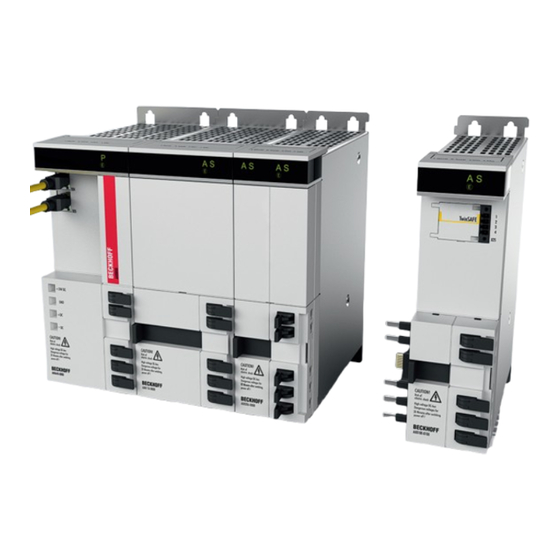
Multi-axis servo system
Hide thumbs
Also See for AX8000 Series:
- User information (246 pages) ,
- Operating instructions manual (146 pages) ,
- System manual (67 pages)

Subscribe to Our Youtube Channel
Related Manuals for Beckhoff AX8000 Series


Summary of Contents for Beckhoff AX8000 Series
- Page 1 AX8000 | Multi-axis servo system Operating instructions | EN 4/24/2020 | Version 1.1 Order No.: TDmlAX-8000-0000-0201...
-
Page 3: Table Of Contents
Version numbers............................... 7 Scope of the documentation .......................... 7 Staff qualification............................... 8 Safety and instruction ............................. 10 Explanation of symbols ........................... 10 Beckhoff Services ............................ 12 For your safety.............................. 13 Safety pictograms ............................ 13 General safety instructions .......................... 14 Product overview............................... 16 Power supply module............................ - Page 4 Table of content DC link ................................ 69 Fieldbus system .............................. 70 Multi-feedback.............................. 71 Motor feedback OCT............................ 74 Digital inputs .............................. 75 Supply networks.............................. 76 Fuse protection ............................... 77 Commissioning .............................. 81 Before commissioning............................. 81 During commissioning............................. 81 Prerequisites during operation ........................ 82 After operation ..............................
-
Page 5: Documentation Notes
1.1.2 and registrations in various other countries: • EP1590927 • EP1789857 • EP1456722 • EP2137893 • DE102015105702 ® EtherCAT is a registered trademark and patented technology, li- censed by Beckhoff Automation GmbH & Co. KG, Germany. Version: 1.1 AX8000 ───... - Page 6 • Use of untrained personnel • Use of unauthorized spare parts Copyright © Beckhoff Automation GmbH & Co. KG, Germany 1.1.4 The copying, distribution and utilization of this document as well as the communication of its contents to others without express autho- rization is prohibited.
-
Page 7: Version Numbers
Product features Only the product properties specified in the current operating in- structions are valid. Further information given on the product pages of the Beckhoff homepage, in emails or in other publications is not authoritative. Scope of the documen- Apart from these operating instructions, the following documents are... -
Page 8: Staff Qualification
Documentation notes Staff qualification These operating instructions are intended for trained control and au- tomation specialists with knowledge of the applicable and required standards and directives. Qualified personnel must have knowledge of drive technology and electrical equipment as well as knowledge of safe working on electri- cal systems and machines. - Page 9 • Assess the work environment • Independently optimize and carry out their work Customer service Customer service personnel and service personnel are verifiably trained and authorized by Beckhoff or the machine manufacturer for the work on the machine or plant. Version: 1.1 AX8000...
-
Page 10: Safety And Instruction
Documentation notes Safety and instruction Read the contents that refer to the activities you have to perform with the product. Always read the chapter For your safety in the op- erating instructions. Observe the warning notes in the chapters so that you can handle and work properly and safely with the product. - Page 11 Documentation notes Notes Notes are used for important information on the product. The possible consequences of failure to observe these include: • Malfunctions of the product • Damage to the product • Damage to the environment Informations This sign indicates information, tips and notes for dealing with the product or the software.
-
Page 12: Beckhoff Services
Beckhoff and the worldwide partner companies offer comprehensive support and service. Support The Beckhoff Support offers technical advice on the use of individ- ual Beckhoff products and system planning. Staff provide assistance 1.7.1 for programming and commissioning complex automation systems and offer a comprehensive training program. -
Page 13: For Your Safety
Safety pictograms On Beckhoff products you will find attached or lasered safety pic- tograms, which vary depending on the product. They serve to pro- tect people and to prevent damage to the products. Safety pic- tograms must not be removed and must be legible for the user. -
Page 14: General Safety Instructions
For your safety General safety instruc- This chapter provides you with instructions on safety when handling the product. This product is not capable of stand-alone operation tions and is therefore categorized as an incomplete machine. The product must be installed in a machine/plant by the machine manufacturer. Read the documentation prepared by the machine manufacturer. - Page 15 For your safety During operation Avoid contact with DC link DC+ and DC- 2.2.2 Measure the voltage on the DC link test contacts DC+ und DC-. Ob- serve the following delay times after disconnecting from the mains supply: • AX8620 and AX8640 30 minutes •...
-
Page 16: Product Overview
Product overview Number Explanation Housing Display; in case of 2-channel modules: left channel 1, right channel 2 Digital inputs X15, channel A and X25, channel B Feedback connection X21 and X22; optional Quick coupling 24 V ; AX bridge EtherCAT connection Quick coupling, DC link and protective earth PE;... -
Page 17: Power Supply Module
Product overview Power supply module Name plate 3.1.1 3.1.1 Number Explanation Order number Serial number Rated input voltage Rated input current Input frequency Maximum ambient temperature Rated output voltage Rated output current Date of manufacture QR code EtherCAT conformity cULus approval EAC conformity CE approval Version: 1.1... - Page 18 Product overview Type key 3.1.2 AX 8x yz - a b c d - 0000 Explanation Product line Servo drive Series AX8000 Supply In combination with "a" Rated output current 20 = 7 A - single-phase supply 20 = 20 A - three-phase supply 40 = 40 A - three-phase supply Supply 0 = three-phase 200 to 480 V...
-
Page 19: Axis Module
Phone: + 49 52 46 / 9 63 - 0 D-33415 Verl Fax. : + 49 52 46 / 9 63 - 198 Automation GmbH & Co. KG Germany www.beckhoff.com info@beckhoff.com Catalog No. 8206-0000-0000 Serial # : 000000100 Input rated voltage... - Page 20 Product overview Type key 3.2.2 AX 8x yz - a b c d - 0000 Explanation Product line Servo drive Series AX8000 Axis module 1 = single-channel servo axis 2 = two-channel servo axis Rated channel current 08 = 1 x 8 A 18 = 1 x 18 A 06 = 2 x 6 A DC link voltage 0 = 0 to 875 V...
-
Page 21: Capacitor Module
Product overview Capacitor module Name plate 3.3.1 3.3.1 Number Explanation Order number Serial number Rated input voltage Maximum ambient temperature DC link capacitance Date of manufacture QR code EtherCAT conformity cULus approval CE conformity Version: 1.1 AX8000 ───... - Page 22 Product overview Type key 3.3.2 AX 8 8 yz - a b c d - 0000 Explanation Product line Servo drive Series AX8000 Option module Option modules 10 = capacitor module Supply 0 = 0 to 875 V Reserved 0 = Standard Hardware features 0 = Standard Execution 0 = Standard ───...
-
Page 23: Product Characteristics
Product overview Product characteristics Short cycle times With the servo drive you can implement fast and highly dynamic po- sitioning tasks through the integrated control technology. EtherCAT enables the ideal connection to the PC-based control technology. With EtherCAT and the AX8000 multi-axis servo system you can achieve minimum cycle times, synchronicity and simultaneity in the drive technology. -
Page 24: Ordering Options
Product overview Ordering options Ordering options are defined via the type key and must be ordered separately. The listed components cannot be retrofitted. Multi-feedback interface The "multi-feedback interface", [Page 71] supports the digital feed- back system EnDat 2.2 or BiSS-C. 3.5.1 There are two further D-Sub 15-pin connectors behind the front cover of the axis module. - Page 25 Product overview The axis modules are optionally available with integrated safety functions . These conform to IEC 61800-5-2 and fulfill the following safety standards: • EN ISO 13849-1:2015, up to Cat 4, PL e • EN 61508:2010, up to SIL 3 •...
-
Page 26: Intended Use
Product overview Intended use The modules of the AX8000 multi-axis servo system may be oper- ated only for the intended activities defined in this documentation, taking into account the prescribed environmental conditions. The components are to be installed only in closed control cabinets in electrical plants or machines and put into operation only as inte- grated components of the plant or machine. -
Page 27: Dual Use
According to the published EU Regulation 1382/2014, commercially available frequency converters are categorized as products with a double purpose of use. The Beckhoff AX8000 multi-axis servo sys- tem thus newly belongs to the dual use products. The goods list, Annex 1 of the Dual Use directive 428/2009 has been amended accordingly: •... -
Page 28: Technical Data
The lifetime of the servo drive may be shortened at temperatures above 40 °C and with encapsulated installation. Beckhoff products are designed for operation under certain environ- mental conditions, which vary according to the product. The follow- ing specifications must be observed for operation and environment in order to achieve the optimum service life of the products. -
Page 29: Power Supply Modules
Technical data Power supply modules • 100 to 480 V Electrical data Single-phase Three-phase AX8620-0000 AX8620-0000 AX8640-0000 Mains supply Rated input current [A 17.5 Maximum rated input current [A Rated supply voltage [V 1 x 100 3 x 200 / 480 -10% -10% +10%... -
Page 30: Axis Modules
Technical data Axis modules • 0 to 875 V Electrical data Single-channel Two-channel AX8108-0000 AX8118-0000 AX8206-0000 Rated output current [A] Per channel: 6 24 V current consumption without holding brake [mA] Minimum rated output current with full current resolu- tion [A] Power loss Without holding brake [W+W/A] At 230 V... -
Page 31: Capacitor Module
Technical data Capacitor module Electrical data AX8810-0000 DC link Maximum voltage [V Capacitance [µF] 1755 Mechanical data AX8810-0000 Width [mm] Height without connectors [mm] Depth without connectors / accessories [mm] Weight [kg] Brake resistor [+] • Dimensions according to the chapter "Dimensional drawings", [Page 34] Electrical data AX2090-BW80-xxxx... -
Page 32: Dimensional Drawings
Technical data Dimensional drawings • Dimensions without connectors and cables • All figures in millimeters Narrow modules The following table provides you with information regarding which modules can be assigned to the dimensional drawing: 4.6.1 Power supply mod- Axis modules Capacitor modules ules AX8620... - Page 33 Technical data Wide modules The following table provides you with information regarding which modules can be assigned to the dimensional drawing: 4.6.2 Power supply modules Axis modules AX8640 AX8118 R2,75 R2,75 Version: 1.1 AX8000 ───...
- Page 34 Technical data Brake resistor [+] • All dimensions in millimeters according to tables 4.6.3 AX2090-BW80-1000 Dimensions according to the dimensional drawing O [mm] R [mm] H [mm] M [mm] U [mm] AX2090-BW80-1600 Dimensions according to the dimensional drawing O [mm] R [mm] H [mm] M [mm]...
- Page 35 Technical data AX209-BW80-2000 Dimensions according to the dimensional drawing O [mm] R [mm] H [mm] M [mm] U [mm] AX209-BW80-3200 Dimensions according to the dimensional drawing O [mm] R [mm] H [mm] M [mm] U [mm] Version: 1.1 AX8000 ───...
-
Page 36: Scope Of Supply
Scope of supply Check missing or damaged parts Check your delivery for completeness. If any parts are missing or became damaged during transport, contact the carrier, vendor or our service department immediately. The scope of delivery always includes the following documents: Translation of the original in- Instruction leaflet structions... -
Page 37: Packaging
Scope of supply Packaging Instructions for handling are printed on the packaging: Symbol Explanation That is the highest and lowest temperature at +55 °C which you may store. -25 °C This is the correct position for the packaging. The packaging must be protected from moisture. The contents are fragile. -
Page 38: Transport And Storage
Transport and storage WARNING Protect the servo drive against damage Protect the servo drive against damage during transport and stor- age and adhere to the conditions. Damage may result in hazardous voltages being present on the housing or exposed components and can lead to serious or even fatal injuries. -
Page 39: Transport
Transport and storage Transport Avoid high mechanical stresses Use suitable means of transport and secure servo drives against high mechanical stress. High mechanical stresses damage the servo drive and individual components. All modules can be transported without aids. Long-term storage Observe the maximum storage time Do not exceed a maximum storage time of five years. -
Page 40: Technical Description
Therefore, use so-called AC/DC-sensitive residual current circuit breakers type B, in which DC current is also accounted for. Beckhoff recommends residual current circuit breakers with switch-on delay. Safe system stop A power failure can lead to the uncontrolled run-out of the drive axes. -
Page 41: Wide Voltage Range
Technical description Wide voltage range Due to the wide voltage range of the power supply modules, the AX8000 multi-axis servo system can be operated worldwide on dif- ferent voltage systems. All networks with a grounded center point are permitted; TT / TN. Data are given below for the wide voltage range of the power supply modules for the different supply networks: Single-phase supply networks Three-phase supply networks... -
Page 42: Dimensioning
Technical description Dimensioning Important information on the DC link capacitance, the total motor ca- ble lengths and the dimensioning of the 24 V control voltage can be found below. Subsequently, there is a practical example. DC link capacitance Observe the maximum chargeable DC link capacitance 7.5.1 The maximum chargeable DC link capacitance must be considered when designing the machine or plant:... - Page 43 Technical description Total motor cable length In compliance with the EMC category C3, various total motor cable lengths apply to the AX8000 multi-axis servo system. 7.5.2 Without mains choke Motor cable length Total motor cable Number of axes per length drive system Maximum 25 m per Maximum 300 m per...
- Page 44 Technical description Practical example The configured 480 V drive system consists of: 7.5.3.1 Num- Component Servomotors from the AM8031-0D21 series with a cable length of 4 m, 10 m, 15 m and 22 m Servomotors from the AM8051-0G21 series with a cable length of 16 m, 18 m, 21 m and 25 m Dual-axis modules from the AX8206 series Power supply modules from the AX8620 series Total standstill current I...
-
Page 45: Display
Technical description Display Information about the states of the individual modules is shown on the display of the AX8000 multi-axis servo system. There are differ- ent symbols for each module. Display black: The module is switched off. Power supply module dis- Information about the meaning of the different symbols on the dis- play of the power supply module is given below: 7.6.1... - Page 46 Technical description Mains voltage P = Power supply Power symbol lights up green: The mains voltage is connected, and the DC link is charged. Symbol flashes green: The DC link is being charged / discharged. Fast blinking: DC link voltage > 48 V Slow flashing: DC link voltage ≤...
- Page 47 Technical description Axis module display In the case of a two-channel axis module, the display is vertically di- vided. The left column shows the symbols for channel A, the right 7.6.2 column shows the symbols for channel B. The EtherCAT symbol is shown in the center.
- Page 48 Technical description Information on the meaning of the different symbols on the display of the safety axis module is given below: Safety S = Safety Safety symbol lights up green: No safety error. Safety symbol lights up red: The axis is in state “STO”. Symbols of EtherCAT, axis module and safety light up green: The safety axis module is in the normal operating state.
-
Page 49: Capacitor Module
• AX8602 axis module; 2 x 6 A • AX8108; 8 A Beckhoff recommends that you place the optional capacitor module 2 directly adjacent to the power supply module 1. Construct the AX8000 multi-axis servo system in decreasing order from the high- est to the lowest rated output current. -
Page 50: Mechanical Installation
Mechanical installation Preparation WARNING Establish the voltage-free and de-energized condition Remove all fuses in the supply network and turn off the main switch on the control cabinet. Secure the control cabinet against being switched on again. Although a motor is no longer rotating, voltage on the control and power connections or a residual voltage in the capacitors of the servo drive can lead to serious injuries. - Page 51 Mechanical installation The following illustration contains recommended dimensions that you should observe when mounting the servo drive in the control cabinet: Number Explanation Control cabinet door Conductive and galvanized mounting plate Cable duct Cable duct Version: 1.1 AX8000 ───...
- Page 52 Mechanical installation Drilling pattern Beckhoff universal drilling pattern 8.1.1 You have the possibility – at any time and without having to drill new holes – to change the configuration of the servo drive modules if you provide the mounting plate with the universal drilling pattern.
-
Page 53: Modules
Mechanical installation Modules Mounting example This chapter provides information on the mounting of power supply modules and other modules. A power supply module and other axis modules are bayed as an example. Power supply modules ► Screw screws into the control cabinet mounting plate in accor- dance with the drilling pattern 8.2.1 ►... - Page 54 Mechanical installation ► Place the axis module 1 at the right side of the power supply module 2 onto the screw 3 and carefully press against the mounting plate 4 ► Once again, guide the screws 1 through the rectangular cut-outs in the module housing 2 ►...
- Page 55 Mechanical installation ► On all modules that you wish to connect, open the quick connec- tors 1 and place them in the 90° position ► Slide all bars 2 for the AX bridge to the left ► Close all quick connectors again The modules are now connected to one another.
-
Page 56: Electrical Installation
Electrical installation WARNING Avoid contact with DC link DC+ and DC- Measure the voltage on the DC link test contacts DC+ und DC-. Keep to the waiting times after disconnection from the supply net- work: • 30 minutes for AX8620 and AX8640 •... - Page 57 The Beckhoff software "TC Motion Designer" is avail- able for energy management purposes. Control cabinet structure You must dimension the control cabinet in such a way that you can install all components with the prescribed spacing.
-
Page 58: Block Diagrams
Electrical installation Block diagrams Sample connection scenarios are presented below using schematic connection diagrams for the power supply modules and axis mod- ules. AX8620 9.2.1 9.2.1 Number Explanation Connection socket for incoming EtherCAT cable Connection socket for outgoing EtherCAT cable Measuring and test contacts on the devices Quick coupling of the AX8000 multi-axis servo system;... - Page 59 Electrical installation AX8640 9.2.2 9.2.2 Number Explanation Connection socket for incoming EtherCAT cable Connection socket for outgoing EtherCAT cable Measuring and test contacts on the devices Quick coupling of the AX8000 multi-axis servo system; AX bridge Optional brake resistor When using an optional brake resistor on the AX8000 multi-axis servo system, the bridge of the 10-pin supply plug "X01"...
- Page 60 Electrical installation AX81x8 9.2.3 9.2.3 Number Explanation Quick coupling of the AX8000 multi-axis servo system; AX bridge ZK4800-80xx-xxxx motor cable; including OCT ─── AX8000 Version: 1.1...
- Page 61 Electrical installation AX8206 9.2.4 9.2.4 Number Explanation Quick coupling of the AX8000 multi-axis servo system; AX bridge ZK4800-80xx-xxxx motor cable; including OCT Version: 1.1 AX8000 ───...
-
Page 62: Grounding
Electrical installation Grounding The ground connection of all relevant components must be made with the largest possible cross-section, with a low impedance, over a wide area and via a short connection to a conductive fastener with a wide area. The shields have to be applied with a sufficiently large contact area on both sides. - Page 63 Electrical installation Module connection 9.3.1 9.3.1 The connection of the individual modules in a drive system takes place via the grounding hangers 1. These are each mechanically locked to the right-hand earthing bolt of the module and swiveled onto the left-hand earthing bolt of the adjacent module, where they are mechanically locked by the nuts and serrations.
- Page 64 Electrical installation ► Screw the nut 6 onto the earthing bolt 5 on top of the grounding hanger 1 ► Do not use a spring washer 7 ► Tighten both nuts firmly ► Observe tightening torques: Components Tightening torque [Nm] Hexagonal nut with serration ►...
- Page 65 Electrical installation Protective earth 9.3.2 9.3.2 The protective earth is established via the left-hand earthing bolt on the power supply module and the mounting plate on the control cab- inet. The connection is made via a cable with a ring-shaped cable lug and spring washer 1.
-
Page 66: Power Supply
Observe the order of connection The rated current of the device should reduce from the power sup- ply module. Beckhoff recommends the following order of connec- tion of the modules: • AX8640 – AX8118 – AX8206 – AX8108... -
Page 67: Voltage Input
Electrical installation Voltage input Do not remove the bridge between R and R Bint+ Proper commissioning is only possible if the bridge between the terminal points R and R is not removed. Alternatively, an exter- Bint+ nal brake resistor can be connected. Without this measure the AX8000 multi-axis servo system will be shut down with an error message. -
Page 68: Brake Chopper
Electrical installation Brake chopper Remove the bridge between contact points R and R Before connecting the external brake resistor, remove the bridge between the contacts R and R Establish the protective earth via the earthing bar Connect the protective earth of the external brake resistor to the earthing bar in the control cabinet. -
Page 69: Dc Link
Electrical installation DC link No external DC link group possible In order to avoid damaging the AX8000 multi-axis servo system, an external DC link group with a servo drive from the AX5000 series is not permissible. ZS4800-2001 9.7.1 AX8620 • X01 slot on AX8620 power supply modules Terminal point Connection n.c. -
Page 70: Fieldbus System
Electrical installation Fieldbus system The EtherCAT real-time Ethernet fieldbus is available in the AX8000 multi-axis servo system. EtherCAT 9.8.1 9.8.1 • X04 connection and X05 connection in case of AX8620 and AX8640 power supply modules Terminal point Connection X04 IN Incoming EtherCAT line X05 OUT Outgoing EtherCAT line... -
Page 71: Multi-Feedback
Electrical installation Multi-feedback An optional interface is available for the AX8xxx-0x10 modules. EnDat 2.2 or BiSS C You have the possibility to use the optional interface EnDat 2.2 and BiSS C in the following cases: 9.9.1 • As a commutation encoder, for example with linear motors •... - Page 72 Electrical installation Definition of slots X a b Explanation Name Slot Channel 1 = channel 1 2 = channel 2 Number of the connector 1 = first connector 2 = second connector AX81xx-0x10 Two D-Sub connections are available for the AX81xx-0x10 single- axis module: •...
- Page 73 Electrical installation AX82xx-0x10 A D-Sub slot is available in each case for the AX82xx-0x10 dual- axis module: • Left slot X11: assignment to the left axis channel 1 • Right connection X21: assignment to the right axis channel 2 EnDat 2.2 BiSS C n.c.
-
Page 74: Motor Feedback Oct
Motor feedback OCT For the axis modules AX81xx and AX8206 you need a combined motor connector and feedback connector. The connector is part of 9.10 the preassembled Beckhoff motor cable. ZS4800-2013 Maximum output current for the motor brake B- and B+ 9.10.1 AX8108 and AX8206 = 1 A... -
Page 75: Digital Inputs
Electrical installation Digital inputs You need a connector for the AX81xx and AX8206 axis modules. The use of terminal points 1 and 2 has a different function with the 9.11 AX8xxx-x0xx and AX8xxx-x1xx axis modules. ZS4800-2015 Support for safety functions STO and SS1 9.11.1 Before putting the axis modules with the order designation AX8xx- x1xx into operation, read the documentation for:... -
Page 76: Supply Networks
Electrical installation Supply networks Use an isolating transformer 9.12 Use an isolating transformer with asymmetrically grounded or un- grounded 100 – 480 V networks. The system will be damaged or destroyed if you do not use an iso- lating transformer under these circumstances. EMC law in Europe In Europe, the AX8000 multi-axis servo system may be operated on an IT network only with an isolating transformer on account of... -
Page 77: Fuse Protection
Electrical installation Fuse protection Observe fuses and data for operation and environment 9.13 The servo drives are equipped with integrated self-protection. The recommended fuses are used for line protection. Adhere to the di- mensioning according to the prescribed data for operation and en- vironment. - Page 78 Electrical installation UL-compliant Circuit breakers are not permitted 9.13.2 Circuit breakers are not permitted for external fusing of the UL net- work. Use exclusively the UL mains fuses specified in this chapter. Fuse holders with UL approval Before implementing a UL configuration, it is mandatory that you contact your UL certificate authority and discuss the necessary boundary conditions.
- Page 79 Electrical installation Device fusing The device fusing can be selected according to various methods: 9.13.3 Conservative Select the fusing in accordance with the maximum device fusing of the corresponding power supply module. Power supply modules Fuse AX8620-0000 Maximum 25 A AX8640-0000 Maximum 50 A Application-oriented Add together the motor currents of all connected servomotors.
- Page 80 Electrical installation Example of the design of the current-limiting circuit breakers in the system group Rated output current of the axis modules is 18 A for AX8118-0000 and 8 A for AX8108-0000 = 26 A Total rated output current = 26 A The system connection must be fused with at least 26 A.
-
Page 81: Commissioning
• Check protective measures against moving and live parts Configuration Beckhoff recommends the use of the latest TwinCAT version and the TwinCAT Drive Manager 2 for the configuration of new projects. • Create a new TwinCAT project and select the target system •... -
Page 82: Prerequisites During Operation
Commissioning Prerequisites during op- • Pay attention to atypical noise development 10.3 eration • Pay attention to smoke development • Always check drive surfaces and cables for dirt, leaks, moisture or dust • Check temperature development • Observe recommended maintenance intervals •... -
Page 83: Maintenance And Cleaning
Maintenance and cleaning WARNING Ensure safe condition for cleaning work Basically, electronic devices are not fail-safe. The condition is al- ways safe when the unit is switched off and not energized. For cleaning work, place the connected servo drives and the machine in a safe state. -
Page 84: Accessories
Accessories Use accessories with UL approval Accessories with UL approval are also required for the operation of the AX8000 in the USA or Canada. Brake resistor 12.1 12.1 Regenerative energy is converted into heat via the brake resistors of the AX2090-BW80 series when braking a servo motor. For further information on the brake resistor, read the translation of the original instructions for the brake resistors of the AX2090-BW80- xxxx series. -
Page 85: Decommissioning
Serious or even fatal injuries may result if this is ignored. Do not remove components from the products Only Beckhoff Automation GmbH & Co. KG is permitted to remove components. Contact Beckhoff Service if you have any questions. -
Page 86: Disposal
The trans- 13.2.1 port costs are borne by the sender. Send the used devices with the note "For disposal" to: Beckhoff Automation GmbH & Co. KG "Service" Building Stahlstrasse 31 D-33415 Verl You can also contact a certified waste disposal company in your area that deals with old electrical and electronic devices. -
Page 87: Guidelines And Standards
Guidelines and Standards Test procedures and certifications vary by product. Beckhoff prod- ucts are certified and tested according to the following directives and standards. Standards EN 6100-6-2:2005 "Electromagnetic compatibility (EMC). Generic standards. Immunity 14.1 for industrial environments" EN 61000-6-4:2007+A1:2011 "Electromagnetic compatibility (EMC). Generic standards. Emission standard for industrial environments"... -
Page 88: Guidelines
Guidelines and Standards Guidelines 2014/35/EU Low Voltage Directive 14.2 2011/65/EU RoHS Directive 2014/30/EU EMC Directive Installation with protective conductor connection When installing electrical systems and components, the protective conductors must be connected first. They must be disconnected last when uninstalling. Depending on the magnitude of the leakage currents, observe the following regulations for the implementation of the protective con- ductor connection:... -
Page 89: Test Centers
The cURus logo can be found on the name plate. EU conformity Placing at disposal 14.4 Beckhoff Automation GmbH & Co KG will be pleased to provide you with EU declarations of conformity and manufacturer's declara- tions for all products on request. Please send your request to: info@beckhoff.com Version: 1.1... -
Page 90: Ul Certification
Guidelines and Standards UL certification The modules may be used as components in a system with a UL- Listing test mark. 14.5 USA and Canada The English translation is binding 14.5.1 Note that all statements made in this chapter on UL certification are binding only in the English version. -
Page 91: Index
Index I n d e x Drive-integrated safety technology 25 Multi-feedback interface 24 Accessories Brake resistor 84 Pictograms 10 Power derating 28 Brake resistor [+] Documentation 84 Technical data 31 Safety 13 DC link capacitors 15 De-energized and voltage-free condition 15 Cable lengths 43... - Page 92 Beckhoff Automation GmbH & Co. KG Hülshorstweg 20 D-33415 Verl www.beckhoff.com info@beckhoff.com More Information: www.beckhoff.com/ax8000...
Need help?
Do you have a question about the AX8000 Series and is the answer not in the manual?
Questions and answers