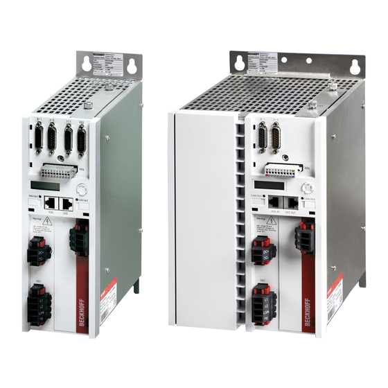
Beckhoff AX5000 Series Start-Up
Hide thumbs Also See for AX5000 Series:
Table of Contents

Advertisement

Startup
Servo Drive AX5000
(60 A – 170 A)
Please read this document carefully before installing and commissioning the servo drive.
Version: 2.5
BECKHOFF
Date: 2018-05-24
Language: English
Article no.: TDmlAX-5160-0000-0200

Advertisement

Table of Contents
loading

Summary of Contents for Beckhoff AX5000 Series

  • Page 1 Startup Servo Drive AX5000 (60 A – 170 A) Please read this document carefully before installing and commissioning the servo drive. Version: 2.5 BECKHOFF Date: 2018-05-24 Language: English Article no.: TDmlAX-5160-0000-0200...
  • Page 2 BECKHOFF 1 Foreword Drive Technology Notes: Version 2.5 AX5000...
  • Page 3: Table Of Contents

    BECKHOFF Drive Technology 1 Foreword Chapter Page Table of Contents – AX5000 Startup Foreword ....................... 5 Notes on the documentation ................5 Disclaimer ......................5 Trademarks ......................5 Patent Pending ....................5 Copyright ......................6 Documentation issue status ................6 Appropriate use ....................
  • Page 4 Energy management ..................38 EMC, earthing, screen connection and potential ..........39 Control cabinet ....................39 Appendix ......................40 Support and Service ..................40 8.1.1 Beckhoff's branch offices and representatives ..........40 8.1.2 Beckhoff Headquarters..................40 8.1.3 Beckhoff Support ....................40 8.1.4 Beckhoff Service ....................
  • Page 5: Foreword

    “AX5000 System manual” that can be CAUTION downloaded from our website at www.beckhoff.com. If you do not have access to the “AX5000 System manual” please refrain from working on the AX5000 and notify our support division.
  • Page 6: Copyright

    1 Foreword Drive Technology Copyright © Beckhoff Automation GmbH & Co. KG The reproduction, distribution and utilization of this document as well as the communication of its contents to others without express authorization are prohibited. Offenders will be held liable for the payment of damages. All rights reserved in the event of the grant of a patent, utility model or design.
  • Page 7: Appropriate Use

    The defect servo drive AX5203-0000-x0xx should be replaced with an AX5203-0000-x01x to avoid changes in the TC System Manager. When downgrading, the desired Firmware (FW v1.00 - FW v1.05) must also be requested from Beckhoff Automation GmbH & Co. KG. AX5000...
  • Page 8: For Your Safety

    Staff qualification Only technical personnel with knowledge of control and automation technology may carry out any of the illustrated work steps on the Beckhoff software and hardware, in particular on the servo drive AX5000. The technical personnel must have knowledge of drive technology and electrical systems and must also know to work safety on electrical equipment and machines.
  • Page 9: Description Of Symbols

    BECKHOFF Drive Technology 2 For your Safety Description of symbols The following safety symbols with a adjoining safety advise are used in this manual. You have to read the adjoining safety advice carefully and adhere it strictly. Symbols that warn of personal injury: Acute risk of injury! This is an extremely dangerous situation.
  • Page 10: Notes For The Servo Drive Ax5000

    The servo drives of the AX5000 series are not designed for stand-alone operation and must always be installed in a machine or system. After installation the additional documentation and safety instructions provided by the machine manufacturer must be read and followed.
  • Page 11 BECKHOFF Drive Technology 2 For your Safety Notes on operation of the servo drive AX5000: • Carefully read this manual before using the servo drive thoroughly, paying particular attention to the safety instructions. In the event of any NOTE uncertainties please notify your sales office immediately and refrain from working on the servo drive.
  • Page 12: Guidelines And Standards

    Drive Technology Guidelines and Standards CE conformity Supply of EC decleration of conformity: Beckhoff Automation GmbH & Co. KG will gladly provide you with the certificates and manufacturer's declaration for all products on request at: NOTE info@beckhoff.com. Hazard to individuals! Servo drives are not covered by the EC Machinery Directive.
  • Page 13: Ul-Listing In Usa And Canada

    BECKHOFF Drive Technology 3 Guidelines and Standards UL-Listing in USA and Canada The following servo drives from the AX5000 series have a UL-Listing and must bear the CUS symbol AX5000 with UL-Listing AX5160, AX5172, AX5190, AX5191, AX5192 und AX5193 on the name plate. If you wish to operate an AX5000 in USA or Canada , please check that there is a CUS symbol on the name plate.
  • Page 14: Electrical Isolation According To En 50178 / Vde 160

    BECKHOFF 3 Guidelines and Standards Drive Technology Drive intended for use over a range of motor sizes. Internal motor overload protection level is adjustable: The internal motor protection is parameterised via the IDN P-0-0062 “Thermal motor model”, based on the value of the IDN S-0-0111 “Motor continuous stall current”. The IDN P-0-0062 “Time constant”...
  • Page 15: Product Description

    4 Product description Product description The servo drives of the AX5000 series are available as single- or multi-channel versions and are optimised in terms of function and cost-effectiveness. In conjunction with EtherCAT, the real-time Ethernet system, the integrated control technology offers minimum cycle times and supports fast, highly dynamic positioning tasks.
  • Page 16: Accessories

    Drive Technology 4.2.2 Accessories A comprehensive list of accessories can be found in the complete Beckhoff catalogue or on our website at www.beckhoff.com. Accessories with UL-Listing! If you wish to operate an AX5000 in an economic area that requires a UL- Listing, please make sure that the accessories also have a UL-Listing.
  • Page 17: Technical Data

    In accordance with the WEEE 2012/96/EG Directives we take old devices and accessories back for professional disposal, provided the transport costs are taken over by the sender. Send the devices with the note “For disposal” to: Beckhoff Automation GmbH & Co. KG Huelshorstweg 20 D-33415 Verl AX5000 Version 2.5...
  • Page 18: Electrical Data

    BECKHOFF 4 Product description Drive Technology 4.4.2 Electrical data Electrical Data AX5160 AX5172 AX5190 AX5191 AX5192 AX5193 Rated output current 60 A 72 A 90 A 110 A 143 A 170 A Minimum rated motor current 25 A 40 A...
  • Page 19: General Overview (Ax5160 And Ax5172)

    BECKHOFF Drive Technology 4 Product description General overview (AX5160 and AX5172) The servo drive illustrated below is an AX5172; the AX5160 is structurally similar Item description: No Designation No Designation 1 X4x – optional slot for expansion cards 9 X01 – mains supply 400 – 480 V 2 X3x –...
  • Page 20: General Overview (Ax5190 And Ax5191)

    BECKHOFF 4 Product description Drive Technology General overview (AX5190 and AX5191) Item description: No Designation No Designation 1 X4x – optional slot for expansion cards 9 X14 – sensor for motor temperature and brake 2 X3x – optional slot for safety card...
  • Page 21: General Overview (Ax5192 And Ax5193)

    BECKHOFF Drive Technology 4 Product description General overview (AX5192 and AX5193) Item description: No Designation No Designation 1 X4x – optional slot for expansion cards 9 X14 – sensor for motor temperature and brake 2 X3x – optional slot for safety card 10 X07 –...
  • Page 22: Overview Of Connectors/Terminal Points

    BECKHOFF 4 Product description Drive Technology Overview of connectors/terminal points 4.8.1 X01 – voltage input 4.8.1.1 AX5160 and AX5172 Terminal point Connection Phase L1 Phase L2 Phase L3 Protective conductor 4.8.1.2 AX5190 and AX5191 Terminal point Connection Phase L1 Phase L2...
  • Page 23: X13 - Motor Connection

    BECKHOFF Drive Technology 4 Product description 4.8.2.2 AX5190 and AX5191 Terminal point Connection RB + External brake resistor + RB - External brake resistor - 4.8.2.3 AX5192 and AX5193 Terminal point Connection RB + External brake resistor + RB - External brake resistor - 4.8.3...
  • Page 24: X02 - Dc Link System

    BECKHOFF 4 Product description Drive Technology 4.8.3.3 AX5192 and AX5193 Terminal point Connection Motor connection U Motor connection V Motor connection W Protective conductor 4.8.4 X02 – DC link system Serious risk of injury through high electrical voltage! 875 V DC voltage at the DC link terminals. Dangerous voltage may be...
  • Page 25: X03 - 24 Vdc Supply

    BECKHOFF Drive Technology 4 Product description 4.8.4.3 AX5192 and AX5193 Terminal point Connection ZK + Zk + ZK – Zk – 4.8.5 X03 – 24 V supply Terminal Connection Current consumption point 24 V - periphery Depending on the connected DC -0/+25% (e.g.
  • Page 26: X11 - Feedback, High-Resolution

    BECKHOFF 4 Product description Drive Technology Terminal point Connection Output current Output voltage (U 24 V 1 A max. Input 0 Input 1 Input 2 Input 3 Input 4 Input 5 Input 6 Input 7 or output (configurable) (U 24 V 0.5 A max.
  • Page 27: X12 - Resolver/Hall

    BECKHOFF Drive Technology 4 Product description 4.8.9 X12 – resolver/hall Feedback system Resolver Analog Hall sensor Temperature n.c. (only PTC, Klixon or bimetal!) Switchpoint: 1300 Ω ± 3% AGND n.c. COS - (S3) n.c. SIN - (S4) n.c. REF - (R2) n.c.
  • Page 28: Dimensions

    BECKHOFF 4 Product description Drive Technology Dimensions The specified measurements relate to the actual device, without connectors and cables. The fitting dimensions for control cabinet installation can be found in section "Mechanical installation Installation examples". AX5160, AX5172, AX5190, AX5191, AX5192, AX5193...
  • Page 29: Installation

    BECKHOFF Drive Technology 5 Installation Installation Caution – Risk of injury! • The servo drives may only be installed by trained, qualified personnel. The qualified personnel must know and comply with the national accident WARNING prevention regulations. • Safety boots must be worn.
  • Page 30: Installation In The Control Cabinet

    BECKHOFF 5 Installation Drive Technology 5.1.1 Installation in the control cabinet [mm] [mm] [mm] ≥ 300 5160 and 5172 4 x M5 ≥ 300 5190 and 5191 4 x M8 ≥ 500 5192 and 5193 4 x M8 Caution - Risk of injury through electric shock! The mounting plate must be earthed according to the statutory regulations.
  • Page 31: Installation Example

    BECKHOFF Drive Technology 5 Installation 5.1.2 Installation example [mm] [mm] ≥ 180 5160 and 5172 ≥ 180 5190 and 5191 ≥ 180 5192 and 5193 AX5000 Version 2.5...
  • Page 32: Installation Of The Shroud (Optional)

    BECKHOFF 5 Installation Drive Technology 5.1.3 Installation of the shroud (optional) Remove the screws 1 (Don’t use again.) Position the shroud at the ground of the servo drive. Mount the shroud with the screws 2. (Take the new delivered screws.) Connect the lines at the terminals.
  • Page 33: Electrical Installation

    BECKHOFF Drive Technology 5 Installation Electrical installation UL-Listing! It is essential to observe chapter 3.3 if you wish to operate an AX5000 in an economic area that requires a UL-Listing. Serious risk of injury through electric shock! Due to the DC link capacitors dangerous voltage may persist at the DC link contacts “ZK+ and ZK-“...
  • Page 34: Mains Supply Connection (X01)

    5 Installation Drive Technology 5.2.1 Mains supply connection (X01) The servo drives of the AX5000 series are equipped with a wide voltage input "X01" and can be connected to voltage systems three-phase 400 V - 480 V AC -10% AC +10% Connection to the standard mains supply (TT/TN) with earthed centre is described below.
  • Page 35: Vdc - Supply Network Connection (X03)

    BECKHOFF Drive Technology 5 Installation 5.2.2 24 V - supply network connection (X03) The 24 V connection "X03" is used for supplying control electronics and periphery with DC voltage. The control electronics and the periphery can be supplied separately with two different voltage sources.
  • Page 36: Motors And Cables

    BECKHOFF 5 Installation Drive Technology Motors and cables With longer motor cables the resulting commutation currents can affect the control quality and lead to EMC faults. Use the tables below to check whether motor chokes or mains filters have to be used in your application. When selecting the control cabinet ensure that there is adequate space for motor chokes, mains filters, etc.
  • Page 37: Important Information For Commissioning

    BECKHOFF Drive Technology 6 Important information for commissioning Important information for commissioning Caution – Risk of injury! Electronic equipment is not fail-safe. The machine manufacturer is responsible for ensuring that the connected motors and the machine are WARNING brought into a safe state in the event of a fault in the drive system.
  • Page 38: Project Planning - Important Information

    BECKHOFF 7 Project planning – important information Drive Technology Project planning – important information The more thoroughly a machine or plant project is thought through in advance, the less risk there is of having to carry out expensive modifications during or after commissioning. This applies to both the mechanical and electrical design.
  • Page 39: Emc, Earthing, Screen Connection And Potential

    Use Beckhoff motor and feedback cables as these are optimally adapted to the drive system and reduce interference to a minimum. Ensure that the connectors and cables are properly connected.
  • Page 40: Appendix

    Beckhoff's branch offices and representatives Please contact your Beckhoff branch office or representative for local support and service Beckhoff products! The addresses of Beckhoff's branch offices and representatives round the world can be found on her internet pages: http://www.beckhoff.com You will also find further documentation for Beckhoff components there.

This manual is also suitable for:

Ax5172Ax5190Ax5191Ax5160Ax5192Ax5193

Table of Contents