Beckhoff AX8000 System Manual
Multi-axis servo system
Hide thumbs
Also See for AX8000:
- User information (246 pages) ,
- Operating instructions manual (146 pages) ,
- Manual (51 pages)

Related Manuals for Beckhoff AX8000


Summary of Contents for Beckhoff AX8000
- Page 1 All manuals and user guides at all-guides.com Documentation AX8000 - system manual Multi-axis servo system AX8000 Version: Date: 2017-09-11...
- Page 1 Documentation AX8000 - system manual Multi-axis servo system AX8000 Version: Date: 2017-09-11...
- Page 2 All manuals and user guides at all-guides.com...
-
Page 3: Documented Modules
All manuals and user guides at all-guides.com Documented modules Documented modules This documentation describes the following modules of the AX8000 multi-axis servo system: Supply modules: Axis modules: Option modules: AX8620, AX8640 AX8108, AX8118, AX8206 AX8810 (capacitor module) AX8000 - system manual... -
Page 3: Documented Modules
Documented modules Documented modules This documentation describes the following modules of the AX8000 multi-axis servo system: Supply modules: Axis modules: Option modules: AX8620, AX8640 AX8108, AX8118, AX8206 AX8810 (capacitor module) AX8000 - system manual Version: 1.0... -
Page 4: Table Of Contents
UL-specific chapter ...................... 12 3.3.2 UL-specific notes...................... 12 4 For your safety............................ 13 Staff qualification .......................... 13 Description of symbols........................ 14 Notes on the AX8000 multi-axis servo system ................ 15 5 Handling .............................. 17 Transport ............................ 17 Storage ............................ 17 Disposal ............................ 18 6 Product overview............................. 19 Scope of supply .......................... -
Page 4: Table Of Contents
UL-specific chapter ...................... 12 3.3.2 UL-specific notes...................... 12 4 For your safety............................ 13 Staff qualification .......................... 13 Description of symbols........................ 14 Notes on the AX8000 multi-axis servo system ................ 15 5 Handling .............................. 17 Transport ............................ 17 Storage ............................ 17 Disposal ............................ 18 6 Product overview............................. 19 Scope of supply .......................... - Page 5 Brake resistor - AX2090-BW80..................... 59 12.1.1 Device description...................... 59 12.1.2 Intended use ........................ 59 12.1.3 Special safety notes on brake resistors ................ 60 12.1.4 Product identification...................... 61 12.1.5 Mechanical installation ..................... 61 12.1.6 Electrical installation...................... 62 12.1.7 Technical data........................ 66 13 Support and Service.......................... 67 AX8000 - system manual Version: 1.0...
- Page 5 Brake resistor - AX2090-BW80..................... 59 12.1.1 Device description...................... 59 12.1.2 Intended use ........................ 59 12.1.3 Special safety notes on brake resistors ................ 60 12.1.4 Product identification...................... 61 12.1.5 Mechanical installation ..................... 61 12.1.6 Electrical installation...................... 62 12.1.7 Technical data........................ 66 13 Support and Service.......................... 67 AX8000 - system manual Version: 1.0...
- Page 6 All manuals and user guides at all-guides.com Table of content Version: 1.0 AX8000 - system manual...
- Page 6 Table of content Version: 1.0 AX8000 - system manual...
-
Page 7: Foreword
EP0851348, US6167425 with corresponding applications or registrations in various other countries. ® EtherCAT is registered trademark and patented technology, licensed by Beckhoff Automation GmbH, Germany Copyright © Beckhoff Automation GmbH & Co. KG, Germany. The reproduction, distribution and utilization of this document as well as the communication of its contents to others without express authorization are prohibited. -
Page 8: Documentation Issue Status
The supply, axis and capacitor modules of the AX8000 multi-axis servo system are installed exclusively as components in electrical systems or machines. They may only be put into operation as integrated components of the system. -
Page 8: Documentation Issue Status
The supply, axis and capacitor modules of the AX8000 multi-axis servo system are installed exclusively as components in electrical systems or machines. They may only be put into operation as integrated components of the system. -
Page 9: Dual Use (Eu1382/2014)
The goods list, Annex I of the Dual Use directive 428/2009 has been amended accordingly: • Frequency converters (listed in goods list position 3A225) ≥ 600 Hz are subject to export control. • Frequency converters (AX8000 multi-axis servo system) with a rotary field frequency of 599 Hz are not subject to export control. -
Page 10: Guidelines And Standards
CAUTION manufacturers has provided evidence of CE conformity of the complete machine or system. EU Declaration of Conformity Beckhoff Automation GmbH & Co. KG Hülshorstweg 20 33415 Verl Germany... -
Page 10: Guidelines And Standards
CAUTION manufacturers has provided evidence of CE conformity of the complete machine or system. EU Declaration of Conformity Beckhoff Automation GmbH & Co. KG Hülshorstweg 20 33415 Verl Germany... -
Page 11: Electromagnetic Compatibility (Emc)
The above components are permitted to bear the certification logo on the type plate. If you wish to operate a servo drive from the AX8000 series in the USA or Canadian economic areas, please check whether the cULus sign appears on the type plate. -
Page 11: Electromagnetic Compatibility (Emc)
The above components are permitted to bear the certification logo on the type plate. If you wish to operate a servo drive from the AX8000 series in the USA or Canadian economic areas, please check whether the cULus sign appears on the type plate. -
Page 12: Ul-Specific Chapter
Components of the AX8000 multi-axis servo system must be operated on mains supplies that can supply a maximum current carrying capacity of 5 kA at 480 V UL circuit breakers of class "J"... -
Page 12: Ul-Specific Chapter
Components of the AX8000 multi-axis servo system must be operated on mains supplies that can supply a maximum current carrying capacity of 5 kA at 480 V UL circuit breakers of class "J"... -
Page 13: For Your Safety
Liability limitations All the components of the AX8000 multi-axis servo system are supplied in certain hardware and software configurations appropriate for the conditions of the application. Unauthorized modifications to the hardware and/or software configurations other than those described in the documentation are not permitted, and nullify the liability of Beckhoff Automation GmbH &... -
Page 14: Description Of Symbols
This notice provides important information that will be of assistance in dealing with the product or software. There is no immediate danger to product, people or environment. Note UL note! This symbol indicates important information regarding UL certification. Version: 1.0 AX8000 - system manual... -
Page 15: Notes On The Ax8000 Multi-Axis Servo System
They must be followed during installation, commissioning, production, troubleshooting, maintenance and trial or test assemblies. The multi-axis servo system from the AX8000 series is not capable of running alone. It must always be installed in a machine or system. After installation the additional documentation and safety instructions provided by the machine manufacturer must be read and followed. -
Page 15: Notes On The Ax8000 Multi-Axis Servo System
They must be followed during installation, commissioning, production, troubleshooting, maintenance and trial or test assemblies. The multi-axis servo system from the AX8000 series is not capable of running alone. It must always be installed in a machine or system. After installation the additional documentation and safety instructions provided by the machine manufacturer must be read and followed. - Page 16 ð Avoid contact with highly insulating materials (synthetic fibers, plastic film etc.). ð Place the servo drive on a conductive surface. ð Do not touch the motor connector while the AX8000 is in operation. Version: 1.0 AX8000 - system manual...
- Page 16 ð Avoid contact with highly insulating materials (synthetic fibers, plastic film etc.). ð Place the servo drive on a conductive surface. ð Do not touch the motor connector while the AX8000 is in operation. Version: 1.0 AX8000 - system manual...
-
Page 17: Handling
Forming: Capacitors must be reformed before putting the servo drive into operation. Release all electrical connections and feed the servo drive for about 30 minutes with 230 V (single-phase) at terminals L1/L2 or L2/L3. AX8000 - system manual Version: 1.0... -
Page 17: Handling
Forming: Capacitors must be reformed before putting the servo drive into operation. Release all electrical connections and feed the servo drive for about 30 minutes with 230 V (single-phase) at terminals L1/L2 or L2/L3. AX8000 - system manual Version: 1.0... -
Page 18: Disposal
In accordance with the WEEE 2012/96/EG Directives we take old devices and accessories back for professional disposal, provided the transport costs are taken over by the sender. Send the devices with the note “For disposal” to: Beckhoff Automation GmbH & Co. KG Huelshorstweg 20 D-33415 Verl Version: 1.0... -
Page 19: Product Overview
Product overview Product overview The servo drives from the AX8000 series have a modular design and offer the optimum in function and economy. The supply modules support several axis modules, which can be used in various ways. In conjunction with EtherCAT, the real-time Ethernet system, the integrated control technology offers minimum cycle times and supports fast, highly dynamic positioning tasks. -
Page 20: Name Plate And Type Key
Rated output current EAC approval Rated input voltage Date of manufacture Serial number sticker Rated input current QR code Attachment of the type plate Input frequency EtherCAT conformity Max. ambient temperature cULus certification Type key Version: 1.0 AX8000 - system manual... -
Page 21: Axis Modules
Serial number Output frequency range EAC approval Rated input voltage Date of manufacture CE conformity Max. ambient temperature QR code Serial number sticker Rated output voltage EtherCAT conformity Attachment of the type plate Type key AX8000 - system manual Version: 1.0... -
Page 22: Drive-Integrated Safety Technology
Product overview Drive-integrated safety technology The AX8000 axis modules are also optionally available with integrated safety functions. These correspond to IEC 61800-5-2 and meet the safety standards EN ISO 13849-1:2008 (up to Cat 4, PL e) and IEC 61508:2010 (SIL 3). -
Page 23: General Description
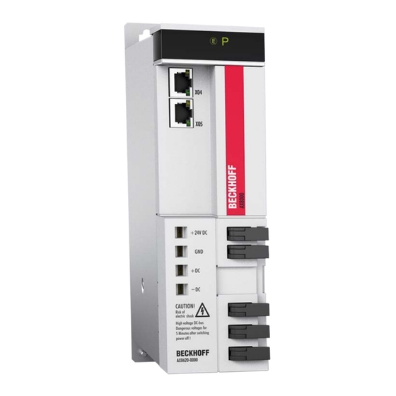
50 V Test contact -DC (DC link) Test contact +DC (DC link) Test contact GND Test contact + 24 V X05 - socket for EtherCAT output X04 - socket for EtherCAT input AX8000 - system manual Version: 1.0... -
Page 23: General Description
50 V Test contact -DC (DC link) Test contact +DC (DC link) Test contact GND Test contact + 24 V X05 - socket for EtherCAT output X04 - socket for EtherCAT input AX8000 - system manual Version: 1.0... -
Page 24: Supply Module - Ax8640
50 VDC. Test contact -DC (DC link) Test contact +DC (DC link) Test contact GND Test contact + 24 V X05 - socket for EtherCAT output X04 - socket for EtherCAT input Version: 1.0 AX8000 - system manual... -
Page 24: Supply Module - Ax8640
50 VDC. Test contact -DC (DC link) Test contact +DC (DC link) Test contact GND Test contact + 24 V X05 - socket for EtherCAT output X04 - socket for EtherCAT input Version: 1.0 AX8000 - system manual... -
Page 25: Axis Modules - Ax8108 And Ax8118
DC link rails (4 and 7). After disconnecting measure the voltage at the DC link rails. Safe working is only possible once the voltage has DANGER dropped below 50 V AX-Bridge: EtherCAT AX-Bridge: 24 V AX8000 - system manual Version: 1.0... -
Page 25: Axis Modules - Ax8108 And Ax8118
DC link rails (4 and 7). After disconnecting measure the voltage at the DC link rails. Safe working is only possible once the voltage has DANGER dropped below 50 V AX-Bridge: EtherCAT AX-Bridge: 24 V AX8000 - system manual Version: 1.0... -
Page 26: Axis Module - Ax8206
Information about our comprehensive range of accessories can be found in the main Beckhoff main catalog or online under http://www.beckhoff.de. Accessories with UL certification! If you want to operate an AX8000 in the US or Canada, please note that any accessories also require UL certification. Version: 1.0... -
Page 27: Technical Description
EtherCAT as a high-performance system communication enables ideal interfacing with PC- based control technology. The AX8000 system enables convenient and fast connection of the DC link of the supply module and several axis modules via an AX Bridge. The connection can be established without tools through spring-loaded terminals for DC link, control circuit and EtherCAT. -
Page 28: System Description
16 µs supports fast and highly dynamic positioning tasks. 7.1.1.1 Wide voltage range In order to simplify use on the most diverse voltage systems, the supply modules of the AX8000 multi-axis servo system are equipped with a wide voltage range. This covers the following different mains supplies: •... -
Page 29: Technical Data
Ambient and operating conditions UL-listed! If you wish to operate a component from the AX8000 multi-axis servo system in a US or Canadian economic area that requires cULus approval, be sure to read section 3.3: "UL ap- proval in the USA and Canada [} 11]". -
Page 29: Technical Data
Ambient and operating conditions UL-listed! If you wish to operate a component from the AX8000 multi-axis servo system in a US or Canadian economic area that requires cULus approval, be sure to read section 3.3: "UL ap- proval in the USA and Canada [} 11]". -
Page 30: Electrical Data - Supply Modules 100 - 240 Vac
Continuous braking power 1 kW (external brake resistor) Max. braking power 9.8 kW (external brake resistor) Mains filter Integrated (category "C3") SCCR value 5 kA for max. 5 s at 240 V mains voltage Version: 1.0 AX8000 - system manual... -
Page 30: Electrical Data - Supply Modules 100 - 240 Vac
Continuous braking power 1 kW (external brake resistor) Max. braking power 9.8 kW (external brake resistor) Mains filter Integrated (category "C3") SCCR value 5 kA for max. 5 s at 240 V mains voltage Version: 1.0 AX8000 - system manual... - Page 31 Continuous braking power 1 kW 2 kW (external brake resistor) Max. braking power 9.8 kW 22 kW (external brake resistor) Mains filter Integrated (category "C3") for up to 5 s at 240 V mains voltage AX8000 - system manual Version: 1.0...
- Page 31 Continuous braking power 1 kW 2 kW (external brake resistor) Max. braking power 9.8 kW 22 kW (external brake resistor) Mains filter Integrated (category "C3") for up to 5 s at 240 V mains voltage AX8000 - system manual Version: 1.0...
-
Page 32: Electrical Data - Supply Modules 400 - 480 Vac
+ 11 W / A at 480 V AC Minimum rated channel current at full current resolution Peak output current 400 V / 480 V 20 A / 18 A 40 A / 36 A for max. 5 s Mains voltage Version: 1.0 AX8000 - system manual... -
Page 32: Electrical Data - Supply Modules 400 - 480 Vac
+ 11 W / A at 480 V AC Minimum rated channel current at full current resolution Peak output current 400 V / 480 V 20 A / 18 A 40 A / 36 A for max. 5 s Mains voltage Version: 1.0 AX8000 - system manual... - Page 33 14 A / 14 A Peak output current / right channel (B), 400 V / 480 V 20 A / 18 A Peak output current as total device current 28 A for max. 5 s Mains voltage AX8000 - system manual Version: 1.0...
- Page 33 14 A / 14 A Peak output current / right channel (B), 400 V / 480 V 20 A / 18 A Peak output current as total device current 28 A for max. 5 s Mains voltage AX8000 - system manual Version: 1.0...
-
Page 34: Mechanical Data
230 mm 230 mm Depth without connectors / accessories 192 mm 192 mm Weight 2.0 kg 2.5 kg Option modules Mechanical data AX8810 Width 60 mm Height without plugs 230 mm Depth without connectors / accessories 192 mm Weight 1,9 kg Version: 1.0 AX8000 - system manual... -
Page 34: Mechanical Data
230 mm 230 mm Depth without connectors / accessories 192 mm 192 mm Weight 2.0 kg 2.5 kg Option modules Mechanical data AX8810 Width 60 mm Height without plugs 230 mm Depth without connectors / accessories 192 mm Weight 1,9 kg Version: 1.0 AX8000 - system manual... -
Page 35: Dimensions
7.2.6 Dimensions The AX8000 multi-axis servo system features only modules with two different dimensions – there are narrow modules and wide modules. The specified measurements refer to the actual devices, without plug connectors and cables. The fitting dimensions for control cabinet installation can be found in section "Mechanical installation [} 38]". -
Page 36: Display
All manuals and user guides at all-guides.com Technical description Display General The display of the AX8000 multi-axis servo system provides a quick overview of the states of the individual modules. Different symbols are used for the individual modules. Display Description Display black: •... -
Page 36: Display
Technical description Display General The display of the AX8000 multi-axis servo system provides a quick overview of the states of the individual modules. Different symbols are used for the individual modules. Display Description Display black: • The module is switched off. - Page 37 The display for the situation when the two-channel safety axis module has reached its operating state is shown below. Display Description EtherCAT, axis and safety symbols light up green: • The safety axis module is in normal operating state. AX8000 - system manual Version: 1.0...
- Page 37 The display for the situation when the two-channel safety axis module has reached its operating state is shown below. Display Description EtherCAT, axis and safety symbols light up green: • The safety axis module is in normal operating state. AX8000 - system manual Version: 1.0...
-
Page 38: Mechanical Installation
Destruction of the servo drive! Observe the following notes to avoid damage to or destruction of the components during the mechanical installation of the AX8000 multi-axis servo system: Attention • Always install the servo drive vertically. -
Page 38: Mechanical Installation
Destruction of the servo drive! Observe the following notes to avoid damage to or destruction of the components during the mechanical installation of the AX8000 multi-axis servo system: Attention • Always install the servo drive vertically. -
Page 39: Installation Conditions In The Control Cabinet
Appropriate space should be provided for these components, so that adequate ventilation is ensured. Cable duct R2,75 R2,75 Risk of injury through electric shock! The mounting plate must be earthed according to the statutory regulations. R2,75 R2,75 Cable duct AX8000 - system manual Version: 1.0... -
Page 40: Drilling Pattern And Installation Example
Mechanical Installation Drilling pattern and installation example Before you start with the installation, make the threaded holes in the mounting plate according to the universal drilling pattern for screwing on the AX8000 multi-axis servo system. Generic drilling template AX8620 AX8206... -
Page 41: Electrical Installation
60364-4-41:2005 and DIN VDE 0100-410:2007-06. Special features in a drive system: In a drive system, the individual components of the AX8000 multi-axis servo system must be connected via the earthing bolts. In addition, a standard-compliant PE connection must be installed on the start and end modules of the system. -
Page 42: Block Diagram - Ax8620 And Ax8640
Measuring and test contacts on the devices Fast connection of the AX8000 multi-axis servo system (AX bridge) Optional brake resistor Attention: When using the optional brake resistors with the AX8000 servo system, the bridge of the 10-pin supply plug "X01" (between R and R ) must be removed. -
Page 43: Block Diagram - Ax81Xx And Ax82Xx
All manuals and user guides at all-guides.com Electrical installation Block diagram - AX81xx and AX82xx Item no. Explanation Fast connection of the AX8000 multi-axis servo system (AX bridge) Motor cable: ZK4800-80xx-xxxx (including OCT) AX8000 - system manual Version: 1.0... -
Page 43: Block Diagram - Ax81Xx And Ax82Xx
Electrical installation Block diagram - AX81xx and AX82xx Item no. Explanation Fast connection of the AX8000 multi-axis servo system (AX bridge) Motor cable: ZK4800-80xx-xxxx (including OCT) AX8000 - system manual Version: 1.0... -
Page 44: Power Supply
, those for the AX8640 for a max. conductor cross-section of 16 9.3.1 Standard connection to the mains supply (X01) The supply modules of the AX8000 series are equipped with a wide voltage input X01 and can be connected to 1-phase voltage systems between 100 V and 240 V... -
Page 44: Power Supply
, those for the AX8640 for a max. conductor cross-section of 16 9.3.1 Standard connection to the mains supply (X01) The supply modules of the AX8000 series are equipped with a wide voltage input X01 and can be connected to 1-phase voltage systems between 100 V and 240 V... - Page 45 All manuals and user guides at all-guides.com Electrical installation X01 – input terminal AX8620 Commissioning Commissioning of the AX8000 is only possible if the terminal points “R +” and “R -” are bin´ bridged (delivery state) or an external brake resistor is connected to the terminal points “R Note +”...
- Page 45 Electrical installation X01 – input terminal AX8620 Commissioning Commissioning of the AX8000 is only possible if the terminal points “R +” and “R -” are bin´ bridged (delivery state) or an external brake resistor is connected to the terminal points “R Note +”...
-
Page 46: Further Types Of Connection
Connection to an IT network (100 - 240 V) without an isolating transformer EMC law in Europe! In Europe, the AX8000 multi-axis servo system may be operated on an IT network only with an isolating transformer on account of the electromagnetic emission. -
Page 46: Further Types Of Connection
Connection to an IT network (100 - 240 V) without an isolating transformer EMC law in Europe! In Europe, the AX8000 multi-axis servo system may be operated on an IT network only with an isolating transformer on account of the electromagnetic emission. - Page 47 Electrical installation Connection to other mains types (100 - 480 V) with isolating transformer Destruction of the AX8000 multi-axis servo system! The use of an isolating transformer is necessary in every case for asymmetric earthed or non-earthed 100 – 480 V networks.
- Page 47 Electrical installation Connection to other mains types (100 - 480 V) with isolating transformer Destruction of the AX8000 multi-axis servo system! The use of an isolating transformer is necessary in every case for asymmetric earthed or non-earthed 100 – 480 V networks.
-
Page 48: Vdc Supply (X01)
All manuals and user guides at all-guides.com Electrical installation 9.3.3 24 VDC supply (X01) The supply connection X01 is used for supplying the supply modules of the AX8000 with 24 V system voltage. Safe operation When connecting motors with holding brake it is essential to observe the voltage toler- ances. -
Page 48: Vdc Supply (X01)
Electrical installation 9.3.3 24 VDC supply (X01) The supply connection X01 is used for supplying the supply modules of the AX8000 with 24 V system voltage. Safe operation When connecting motors with holding brake it is essential to observe the voltage toler- ances. -
Page 49: Fusing, Ce-Compliant
A power failure can lead to the uncontrolled run-out of the drive axes: linear axis or lifting axes would hit the limit stop unbraked. The supply voltage for the control electronics can be buffered by the UPS of the Industrial PC until all axes have been safely stopped. AX8000 - system manual Version: 1.0... -
Page 50: Terminal Points - Supply Modules
9.4.1 DC link (external DC link-connection currently not permitted) Destruction of the equipment An “external” DC link connection (e.g. AX5000 with AX8000) is currently not permitted. Attention Danger to life due to high voltage on the DC link capacitors! The DC link capacitors RB+ and RB- and the test contacts DC+ and DC- on the... -
Page 51: External And Internal Brake Resistor
X01 – brake resistor terminal AX8620 Input terminal Terminal point Connection Max. wire cross- Tightening torque section Ext. brake resistor - 6 mm (AWG 8) 0.5 – 0.6 Nm (4.4 – 5.3 lbf in) Ext. brake resistor + AX8000 - system manual Version: 1.0... -
Page 51: External And Internal Brake Resistor
X01 – brake resistor terminal AX8620 Input terminal Terminal point Connection Max. wire cross- Tightening torque section Ext. brake resistor - 6 mm (AWG 8) 0.5 – 0.6 Nm (4.4 – 5.3 lbf in) Ext. brake resistor + AX8000 - system manual Version: 1.0... -
Page 52: Ethercat (X04 And X05)
(AWG 6) 1.2 – 1.5 Nm (10.6 – 13.3 lbf in) Ext. brake resistor + 9.4.3 EtherCAT (X04 and X05) Terminal Terminal point Connection X04 (IN) incoming EtherCAT line X05 (OUT) outgoing EtherCAT line Version: 1.0 AX8000 - system manual... -
Page 52: Ethercat (X04 And X05)
(AWG 6) 1.2 – 1.5 Nm (10.6 – 13.3 lbf in) Ext. brake resistor + 9.4.3 EtherCAT (X04 and X05) Terminal Terminal point Connection X04 (IN) incoming EtherCAT line X05 (OUT) outgoing EtherCAT line Version: 1.0 AX8000 - system manual... -
Page 53: Terminal Points - Axis Modules
STO (Safe Torque Off) and SS1 (Safe Stop 1). Attention Before putting the axis module into operation, read the documentation for: • AX8911 - TwinSAFE Drive option for AX8000 series servo drives. AX8000 - system manual Version: 1.0... -
Page 53: Terminal Points - Axis Modules
STO (Safe Torque Off) and SS1 (Safe Stop 1). Attention Before putting the axis module into operation, read the documentation for: • AX8911 - TwinSAFE Drive option for AX8000 series servo drives. AX8000 - system manual Version: 1.0... -
Page 54: Total Motor Cable Length
The 24 V current consumption of all components is: 5.88 A (≤ 50 A ) √ Requirement fulfilled Therefore no mains choke is required. *for the different capacitances, refer to section 7: "Electrical installation [} 41]". Version: 1.0 AX8000 - system manual... -
Page 54: Total Motor Cable Length
The 24 V current consumption of all components is: 5.88 A (≤ 50 A ) √ Requirement fulfilled Therefore no mains choke is required. *for the different capacitances, refer to section 7: "Electrical installation [} 41]". Version: 1.0 AX8000 - system manual... -
Page 55: Option Modules
AX8810-0000 Capacity 4420 µF 1755 µF Max. DC link voltage 425 V 875 V Height 230 mm 230 mm Width 60 mm 60 mm Depth 192 mm 192 mm Weight 1.9 kg 1.9 kg AX8000 - system manual Version: 1.0... -
Page 55: Option Modules
AX8810-0000 Capacity 4420 µF 1755 µF Max. DC link voltage 425 V 875 V Height 230 mm 230 mm Width 60 mm 60 mm Depth 192 mm 192 mm Weight 1.9 kg 1.9 kg AX8000 - system manual Version: 1.0... -
Page 56: Positioning Within The System
AX8620-1000 AX8206 AX8810-1000 AX8108 +24V DC AX8620-1000 AX8810-1000 AX8206 AX8108 +24V DC Supply voltage: 400 V – 480 V With this supply voltage the capacitor module AX8810-0000 can be positioned anywhere within the system. Version: 1.0 AX8000 - system manual... -
Page 57: Project Planning
With a positive tolerance for voltage fluctuation the upper limit value of the wide voltage input of the AX8000 needs to be taken into account. With a negative tolerance of the voltage fluctuation it must be checked whether the decrease in speed caused by the low voltage is permissible. -
Page 58: Control Cabinet
In addition, the control cabinet should have an earthed metal rear panel to which the AX8000 incl. periphery are attached so that safe earthing can be guaranteed. If you are unable to guarantee these conditions you need to earth the AX8000 and the relevant components using an approved cable of adequate size. -
Page 59: Accessories
AX2090-BW80 series are cUL and CSA approved. Absorption of the arising braking energy! The AX8000 multi-axis servo system offers the option of destroying arising braking energy through internal brake resistors. If the built-in resistors do not suffice, an external brake re- Attention sistor can be connected to the AX86xx supply module (terminal X01) 12.1.2... -
Page 60: Special Safety Notes On Brake Resistors
UL- recognized component The brake resistors from the AX2090-BW80 series are certified according to applicable UL and CSA safety requirements. They may therefore be used in products, plants or systems bearing the UL-Listing test mark. Version: 1.0 AX8000 - system manual... -
Page 61: Product Identification
Infographic Item no. Description Drive Technology Accessories BR = brake resistor Servo drives from the AX8000 series 1000 = AX8620-1000 and AX8640-0000, 1 kW, 18 Ω 1600 = AX8620-0000, 1.6 kW, 33 Ω 2000 = AX8640-1000, 2.0 kW, 18 Ω... -
Page 61: Product Identification
Infographic Item no. Description Drive Technology Accessories BR = brake resistor Servo drives from the AX8000 series 1000 = AX8620-1000 and AX8640-0000, 1 kW, 18 Ω 1600 = AX8620-0000, 1.6 kW, 33 Ω 2000 = AX8640-1000, 2.0 kW, 18 Ω... -
Page 62: Electrical Installation
Important notes Danger of injury through electrocution! Injuries can be sustained through electrocution during the mounting and commissioning of the AX8000 multi-axis servo system. WARNING The installation may only be carried out by trained and qualified technical personnel who are well-versed in electrical and automation technology. Furthermore, the national accident prevention regulations must be adhered to. -
Page 62: Electrical Installation
Important notes Danger of injury through electrocution! Injuries can be sustained through electrocution during the mounting and commissioning of the AX8000 multi-axis servo system. WARNING The installation may only be carried out by trained and qualified technical personnel who are well-versed in electrical and automation technology. Furthermore, the national accident prevention regulations must be adhered to. - Page 63 12.1.6.3 Cables Beckhoff Automation GmbH & Co. KG offers preassembled cables for safe, faster and flawless installation of the motors. Beckhoff cables have been tested with regard to the materials, shielding and connectors used. They ensure proper functioning and compliance with statutory regulations such as EMC, UL etc. The use of other cables may lead to unexpected interference and invalidate the warranty.
- Page 63 12.1.6.3 Cables Beckhoff Automation GmbH & Co. KG offers preassembled cables for safe, faster and flawless installation of the motors. Beckhoff cables have been tested with regard to the materials, shielding and connectors used. They ensure proper functioning and compliance with statutory regulations such as EMC, UL etc. The use of other cables may lead to unexpected interference and invalidate the warranty.
- Page 64 120 sec. is used in the calculation. Example 1 Example 2 = 60 s = 40 s Cycle time = 280 s Cycle time = 100 s Duty cycle = 50% Duty cycle = 40% Version: 1.0 AX8000 - system manual...
- Page 64 120 sec. is used in the calculation. Example 1 Example 2 = 60 s = 40 s Cycle time = 280 s Cycle time = 100 s Duty cycle = 50% Duty cycle = 40% Version: 1.0 AX8000 - system manual...
- Page 65 Destruction of the brake resistor and adjacent components! Always ensure adequate ventilation of the brake resistor, since the temperatures of the housing surface may exceed 200 °C. Attention AX8000 - system manual Version: 1.0...
- Page 65 Destruction of the brake resistor and adjacent components! Always ensure adequate ventilation of the brake resistor, since the temperatures of the housing surface may exceed 200 °C. Attention AX8000 - system manual Version: 1.0...
-
Page 66: Technical Data
[W] * at 40 °C [Ω] [mm] [mm] [mm] [mm] [mm] [kg] AX2090-BW80-1000 1000 AX8620-1000 AX8640-0000 AX2090-BW80-1600 1600 AX8620-0000 AX2090-BW80-2000 2000 AX8640-1000 AX2090-BW80-3200 3200 10.3 AX8640-0000 *) 4% output reduction per 10 K temperature difference Dimensional drawings Version: 1.0 AX8000 - system manual... -
Page 67: Support And Service
Beckhoff's branch offices and representatives Please contact your Beckhoff branch office or representative for local support and service on Beckhoff products! The addresses of Beckhoff's branch offices and representatives round the world can be found on her internet pages: http://www.beckhoff.com You will also find further documentation for Beckhoff components there. -
Page 67: Support And Service
Beckhoff's branch offices and representatives Please contact your Beckhoff branch office or representative for local support and service on Beckhoff products! The addresses of Beckhoff's branch offices and representatives round the world can be found on her internet pages: http://www.beckhoff.com You will also find further documentation for Beckhoff components there.
Need help?
Do you have a question about the AX8000 and is the answer not in the manual?
Questions and answers