Beckhoff AX5000 Series Startup Manual
Hide thumbs
Also See for AX5000 Series:
- Function manual (94 pages) ,
- Manual (49 pages) ,
- Start-up (40 pages)

Related Manuals for Beckhoff AX5000 Series


Summary of Contents for Beckhoff AX5000 Series
- Page 1 Startup Servo Drive AX5000 (1.5 A – 40 A) Please read this document carefully before installing and commissioning the servo drive. Version : 4.5 Date: 2015-04-01 BECKHOFF Language: English Article no.: TDmlAX-5000-0000-0200...
- Page 2 BECKHOFF 1 Foreword Drive Technology Notes: Version : 4.5 AX5000...
-
Page 3: Table Of Contents
BECKHOFF Drive Technology 1 Foreword Chapter Page Table of Contents - AX5000 Startup Foreword ....................... 5 Notes on the documentation ................5 Disclaimer ......................5 Trademarks ......................5 Patent Pending ....................5 Copyright ......................6 Documentation issue status ................6 Appropriate use .................... - Page 4 Energy management ..................44 EMC, earthing, screen connection and potential ..........45 Control cabinet ....................45 Appendix ......................46 Support and Service ..................46 8.1.1 Beckhoff's branch offices and representatives ..........46 8.1.2 Beckhoff Headquarters..................46 8.1.3 Beckhoff Support ....................46 8.1.4 Beckhoff Service ....................
-
Page 5: Foreword
“AX5000 User manual” on the enclosed CD or CAUTION can be downloaded from our website at www.beckhoff.com. If you do not have access to the “AX5000 User manual” please refrain from working on the AX5000 and notify our support division. -
Page 6: Copyright
1 Foreword Drive Technology Copyright © Beckhoff Automation GmbH & Co. KG The reproduction, distribution and utilization of this document as well as the communication of its contents to others without express authorization are prohibited. Offenders will be held liable for the payment of damages. All rights reserved in the event of the grant of a patent, utility model or design. -
Page 7: Appropriate Use
Appropriate use The servo drives of the AX5000 series are exclusively designed for torque, speed and position control of suitable asynchronous and synchronous three-phase current motors. The maximum permissible effective motor voltage must be at least equal the effective mains voltage fed into the servo drive. -
Page 8: Documented Servo Drives
BECKHOFF 1 Foreword Drive Technology Council Regulation 428/2009 has been changed accordingly, Frequency inverters (listed in item position 3A225) with „operating frequency of 600 Hz or more“ are now export controlled items. As a consequence some modifications have to be noticed. -
Page 9: Safety
All the components are supplied in particular hardware and software configurations appropriate for the application. Modifications to hardware or software configurations other than those described in the documentation are not permitted, and nullify the liability of Beckhoff Automation GmbH & Co. KG. 2.1.3 Description of safety symbols The following safety symbols with a adjoining safety advise are used in this manual. -
Page 10: Personnel Qualification
The servo drives of the AX5000 series are not designed for stand-alone operation and must always be installed in a machine or system. After installation the additional documentation and safety instructions provided by the machine manufacturer must be read and followed. - Page 11 BECKHOFF Drive Technology 2 Safety Hazard to individuals! • Carefully read this manual before using the servo drive thoroughly, paying particular attention to the safety instructions. In the event of any CAUTION uncertainties please notify your sales office immediately and refrain from working on the servo drive.
-
Page 12: Guidelines And Standards
BECKHOFF 3 Guidelines and Standards Drive Technology Guidelines and Standards CE conformity The servo drives of the AX5000 series comply with the • EC Low-Voltage Directive, 2006/95/EC Applied harmonised standards: 61800-5-1 Hazard to individuals! Servo drives are not covered by the EC Machinery Directive. Operation... -
Page 13: Ul-Listing In Usa And Canada
BECKHOFF Drive Technology 3 Guidelines and Standards UL-Listing in USA and Canada The following servo drives from the AX5000 series have a UL-Listing and must bear the CUS symbol AX5000 with UL-Listing AX5101, AX5103, AX5106, AX5112, AX5118, AX5125, AX5140, AX5201, AX5203 und AX5206 on the name plate. -
Page 14: Ul-Specific Notes
Canada! In Canada use only in combination with unit AX2090-TS50, manufactured by Beckhoff Automation. Electrical isolation according to EN 50178 / VDE 160 The power section (motor connection, DC link connection and mains connection) and the control unit are doubly insulated against each other, so that safe protection against accidental contact is ensured at all terminals of the control unit without additional measures. -
Page 15: Product Description
4 Product description Product description The servo drives of the AX5000 series are available as single- or multi-channel versions and are optimised in terms of function and cost-effectiveness. In conjunction with EtherCAT, the real-time Ethernet system, the integrated control technology offers minimum cycle times and supports fast, highly dynamic positioning tasks. -
Page 16: Accessories
Drive Technology 4.2.2 Accessories A comprehensive list of accessories can be found in the complete Beckhoff catalogue or on our website at www.beckhoff.com. Accessories with UL-Listing! If you wish to operate an AX5000 in USA or Canada , please make sure that the accessories also have a UL-Listing. -
Page 17: Technical Data
BECKHOFF Drive Technology 4 Product description Technical data UL-Listing! It is essential to observe chapter 3.3 if you wish to operate an AX5000 in USA or Canada. 4.4.1 Permissible ambient and operating conditions Ambient / operating conditions Permissible values Ambient temperature during operation 0 °C to +50 °C... -
Page 18: Three-Phase Connection
BECKHOFF 4 Product description Drive Technology Electrical data AX5101 AX5103 AX5106 S1 mode (selection) 120 V 0.3 kVA 0.6 kVA 1.2 kVA 230 V 0.6 kVA 1.2 kVA 2.4 kVA Power dissipation 35 W 50 W 85 W Max. continuous braking power... -
Page 19: Electrical Data - Two-Channel Servo Drive (Ax52Xx)
BECKHOFF Drive Technology 4 Product description 4.4.3 Electrical data - two-channel servo drive (AX52xx) 4.4.3.1 Single-phase connection Electrical data AX5201 AX5203 AX5206 Rated output current / channel 1.5 A Minimum channel current at full current 0.35 A resolution Maximum rated channel current 4.5 A... -
Page 20: Mechanical Data (Single-Channel Servo Drive)
BECKHOFF 4 Product description Drive Technology Electrical data AX5201 AX5203 AX5206 230 V 1.2 kVA 2.4 kVA 4.8 kVA 400 V 2.1 kVA 4.2 kVA 8.3 kVA 480 V 2.5 kVA 5.0 kVA 10.0 kVA Power dissipation 55 W 85 W 160 W Max. -
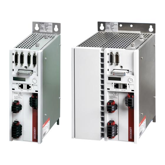
Page 21: General Overview (Ax5101 - Ax5112 And Ax520X)
BECKHOFF Drive Technology 4 Product description General overview (AX5101 – AX5112 and AX520x) The servo drive shown below is a two-channel device. Components that are only available for the second channel are identified in the item description. Item description: No Designation X11 –... -
Page 22: General Overview (Ax5118, Ax5125 Und Ax5140)
BECKHOFF Drive Technology 4 Product description General overview (AX5118, AX5125 und AX5140) The servo drive illustrated below is an AX5140; the devices with 18 A or 25 A are structurally similar apart from pos. 11 "X07" (external brake resistor). Item description:... -
Page 23: Overview Of Connectors/Terminal Points
BECKHOFF Drive Technology 4 Product description Overview of connectors/terminal points 4.7.1 X01 - wide voltage input Connection Tightening Terminal point torque 3-phase 1-phase Phase L1 Phase L1 Phase L2 not used 0,5 -0,6 Nm L3/ N Phase L3 Neutral conductor Protective conductor 4.7.2... -
Page 24: X04, X05 - Ethercat Connection
BECKHOFF 4 Product description Drive Technology 4.7.5 X04, X05 - EtherCAT connection Terminal point Connection X04 (IN) incoming EtherCAT line X05 (OUT) outgoing EtherCAT line 4.7.6 X06 – Digital I/Os Destruction of the AX5000! This connector is not designed for external power supply. It is supplied via the 24 V supply (U ) of connector X03. -
Page 25: X11 (Channel A) , X21 (Channel B) - Feedback, High-Resolution
BECKHOFF Drive Technology 4 Product description 4.7.7 X11 (channel A) , X21 (channel B) - feedback, high-resolution EnDAT / BiSS Hiperface Sin / Cos 1Vpp SIN + SIN + SIN + n.c. GND_5 V GND_9 V GND_5 V GND_5 V... -
Page 26: X13 (Channel A) , X23 (Channel B) - Motor Connection (Power)
BECKHOFF 4 Product description Drive Technology 4.7.9 X13 (channel A) , X23 (channel B) - motor connection (power) (AX5101 - AX5125 und AX520x) Terminal point Connection Motor connection U Motor connection V Motor connection W Protective conductor Shroud Screen 4.7.10... -
Page 27: X07 - Internal And External Brake Resistor
BECKHOFF Drive Technology 4 Product description AX5000-xxxx-0200 (Hardware 2) Terminal point Connection Output current OCT – and temperature OCT + and temperature Signal pair screen Brake GND Brake (U 2.2 A max. Output current The specified output current is the maximum value. The actual value depends on your current configuration. -
Page 28: Dimensions
BECKHOFF 4 Product description Drive Technology Dimensions The specified measurements relate to the actual device, without connectors and cables. The fitting dimensions for control cabinet installation can be found in section "Mechanical installation Installation examples". AX5118, AX5125 and AX5140 AX5101-AX5112 / AX5201-AX5206 All dimensions are in mm Version : 4.5... - Page 29 BECKHOFF Drive Technology 4 Product description AX5000 AX5000 without AX bridge with AX bridge All dimensions are in mm AX5000 Version : 4.5...
-
Page 30: Installation
BECKHOFF 5 Installation Drive Technology Installation Caution – Risk of injury! • The servo drives may only be installed by trained, qualified personnel. The qualified personnel must know and comply with the national accident WARNING prevention regulations. • Safety boots must be worn. -
Page 31: Installation Example - Ax5101-Ax5112 And Ax5201-Ax5206
BECKHOFF Drive Technology 5 Installation 5.1.1.1 Installation example - AX5101-AX5112 and AX5201-AX5206 5.1.1.2 Installation example - AX5118, AX5125 and AX5140 AX5000 Version : 4.5... -
Page 32: Electrical Installation
BECKHOFF 5 Installation Drive Technology Electrical installation UL-Listing! It is essential to observe chapter 3.3 if you wish to operate an AX5000 in USA or Canada. Serious risk of injury through electric shock! Due to the DC link capacitors dangerous voltage may persist at the DC link contacts "X02"... -
Page 33: Mains Supply Connection (X01)
Drive Technology 5 Installation 5.2.1 Mains supply connection (X01) The servo drives of the AX5000 series are equipped with a wide voltage input "X01" and can be connected to voltage systems between single-phase 100 V - 240 V AC -10%... -
Page 34: External Protection, Ul-Compliant
BECKHOFF 5 Installation Drive Technology 5.2.1.3 External protection, UL-compliant Integral solid state short circuit protection does not provide branch circuit protection. Branch circuit protection must be provided in accordance with the Manufacture Instructions, National Electrical Code and any additional local codes. -
Page 35: External Drive System Protection
BECKHOFF Drive Technology 5 Installation 5.2.1.5 External drive system protection Rule of thumb: Determine the total device rated current, multiply by correction factor and round it up to the next higher standard level. Example: 1 x AX5103 + 2 x AX5201 + 2 x AX5203 + 12 A = 21 x 1,1 = 23,1 A ... -
Page 36: Supply Network Connection (X03)
BECKHOFF 5 Installation Drive Technology 5.2.2 24 V - supply network connection (X03) The 24 V connection "X03" is used for supplying control electronics and periphery with DC voltage. The control electronics and the periphery can be supplied separately with two different voltage sources. -
Page 37: Connection Example - Module Ax5901 And Ax5911 (Ax Bridge)
BECKHOFF Drive Technology 5 Installation 5.2.3.1 Connection example - module AX5901 and AX5911 (AX Bridge) This connection option enables a safe system to be set up very quickly. The modules are attached to plug contacts X01, X02 and X03, the relevant slides are pushed to the left and screwed tight. -
Page 38: Connection Example - Wiring In Series Without Ax Bridge
BECKHOFF 5 Installation Drive Technology 5.2.3.2 Connection example - wiring in series without AX Bridge Wire the relevant connections using individual cables. Hazard to inviduals and equipment • Please ensure that the final supply network connection cable is adequately dimensioned. The dimensioning depends on the total rated CAUTION current and must comply with EN60204-1. -
Page 39: Configuration Example, General
BECKHOFF Drive Technology 5 Installation 5.2.4 Configuration example, general AX5000 Version : 4.5... -
Page 40: Connection Diagram Ax5101 - Ax5112 And Ax520X
BECKHOFF 5 Installation Drive Technology 5.2.5 Connection diagram AX5101 – AX5112 and AX520x Version : 4.5 AX5000... -
Page 41: Connection Diagram Ax5118, Ax5125 And Ax5140
BECKHOFF Drive Technology 5 Installation 5.2.6 Connection diagram AX5118, AX5125 and AX5140 AX5000 Version : 4.5... -
Page 42: Motors And Cables
BECKHOFF 5 Installation Drive Technology Motors and cables With longer motor cables the resulting commutation currents can affect the control quality and lead to EMC faults. Use the tables below to check whether motor chokes or mains filters have to be used in your application. When selecting the control cabinet ensure that there is adequate space for motor chokes, mains filters, etc. -
Page 43: Important Information For Commissioning
BECKHOFF Drive Technology 6 Important information for commissioning Important information for commissioning Caution – Risk of injury! Electronic equipment is not fail-safe. The machine manufacturer is responsible for ensuring that the connected motors and the machine are WARNING brought into a safe state in the event of a fault in the drive system. -
Page 44: Project Planning - Important Information
BECKHOFF 7 Project planning – important information Drive Technology Project planning – important information The more thoroughly a machine or plant project is thought through in advance, the less risk there is of having to carry out expensive modifications during or after commissioning. This applies to both the mechanical and electrical design. -
Page 45: Emc, Earthing, Screen Connection And Potential
Use pre-assembled Beckhoff motor and feedback cables as these are optimally adapted to the drive system and reduce interference to a minimum. Ensure that the connectors are properly connected: this applies to the motor connector in particular. -
Page 46: Appendix
Beckhoff's branch offices and representatives Please contact your Beckhoff branch office or representative for local support and service Beckhoff products! The addresses of Beckhoff's branch offices and representatives round the world can be found on her internet pages: http://www.beckhoff.com You will also find further documentation for Beckhoff components there.
Need help?
Do you have a question about the AX5000 Series and is the answer not in the manual?
Questions and answers