
Related Manuals for Beckhoff AX8-1 Series


Summary of Contents for Beckhoff AX8-1 Series
- Page 1 Documentation for AX8911 - TwinSAFE Drive Option TwinSAFE Drive Option for AX8xxx-x1xx Servo Drives Version: 1.0.0 Date: 2017-10-26...
-
Page 3: Table Of Contents
Table of contents Table of contents 1 Foreword .............................. 5 Notes on the documentation...................... 5 Safety instructions .......................... 6 1.2.1 Delivery state ........................ 6 1.2.2 Operator's obligation to exercise diligence ................ 6 1.2.3 Description of safety symbols .................... 7 Documentation issue status...................... 7 2 References .............................. 8 3 System description ........................... 9 The AX8000 multi-axis servo system ..................... - Page 4 Table of contents 8 Diagnostics .............................. 37 Diagnostic display of the AX8xxx axis module ................ 37 AX8xxx Diag history tab........................ 37 Diagnosis History.......................... 38 9 Maintenance............................. 41 10 Service life.............................. 42 11 Decommissioning............................ 43 12 Appendix .............................. 44 12.1 Support and Service ........................ 44 12.2 Certificates............................
-
Page 5: Foreword
Product features Only the product features specified in the current user documentation are valid. Further information given on the product pages of the Beckhoff homepage, in emails or in other publications is not authoritative. Disclaimer The documentation has been prepared with care. The products described are subject to cyclical revision. For that reason the documentation is not in every case checked for consistency with performance data, standards or other characteristics. -
Page 6: Safety Instructions
Offenders will be held liable for the payment of damages. All rights reserved in the event of the grant of a patent, utility model or design. Delivery conditions In addition, the general delivery conditions of the company Beckhoff Automation GmbH & Co. KG apply. Safety instructions 1.2.1... -
Page 7: Description Of Safety Symbols
Foreword 1.2.3 Description of safety symbols In these operating instructions the following symbols are used with an accompanying safety instruction or note. The safety instructions must be read carefully and followed without fail! Serious risk of injury! Failure to follow the safety instructions associated with this symbol directly endangers the life and health of persons. -
Page 8: References
References References Version Title / description 1.4.0 or newer AX8000 StartUp This documentation contains the description of the assembly, installation and operation of an AX8000. 1.4.1 or newer Operating instructions for EL6910 TwinSAFE logic module The document contains a description of the logic functions of the EL6910, and thus also of the AX8911, and their programming 3.1.0 or newer Documentation –... -
Page 9: System Description
System description System description The AX8000 multi-axis servo system Multi-channel drive solutions can be constructed with the AX8000 multi-axis servo system. The required number of single-channel or two-channel axis modules are attached to the central supply module. The modules are connected without screws or tools using the built-in AX-Bridge quick connection system, which is based on spring-loaded terminals. -
Page 10: Product Description
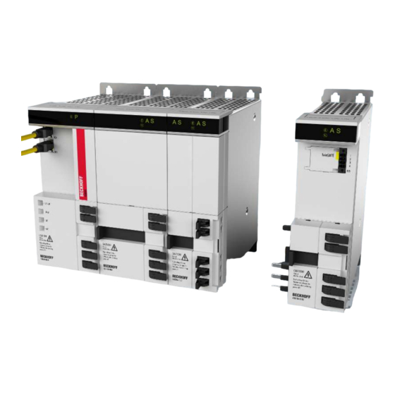
AX8911 - TwinSAFE drive option for AX8000 series servo drives The AX8911 TwinSAFE drive option is an optional extension of the Beckhoff AX8000 servo drive series. There are two versions of the AX8911 option. The first version provides only the STO function via the digital inputs of the AX8000 axis module or via a TwinSAFE (FSoE) connection. -
Page 11: Ax8911 With Safe Motion Functions (Ax8Xxx-X2Xx)
References [} 8]). Intended use The AX8911 TwinSAFE drive option card extends the field of use of the Beckhoff AX8000 servo drive by safety functions that allow it to also be used in the field of machine safety. Observe the intended use! - Page 12 Product description Parameterization Check the parameterization of the TwinSAFE drive option card! The TwinSAFE drive option card determines errors in the parameterization, but no logical testing of the parameters or the loaded safety program can take place. Hence, you must WARNING ensure by means of an acceptance test that the parameterization and the safety program are correct for the application.
- Page 13 Product description Diagnostics / faults Avoid line interruptions! Line interruptions can lead to switch-off. The AX8911 can switch the motors of the AX8000 servo drive torque-free according to the safety project used on it. Any motors that are still WARNING moving coast to a halt.
-
Page 14: Technical Data
Product description Technical data Product designation AX8911 (AX8xxx-x1xx) Number of inputs 2 digital inputs per channel (X15, X25) Status display "S" display on the AX8000 Minimum/maximum cycle time approx. 1 ms / according the project size Fault response time ≤ watchdog times Watchdog time min. -
Page 15: Safety Parameters
Product description Safety parameters Safety functions STO, SS1 Characteristic numbers AX8911 - STO, SS1 (AX8xxx-x1xx) Lifetime [a] Proof test interval [a] not required 3.04E-09 %SIL3 of PFH 3% of SIL3 9.20E-05 %SIL3 of PFD 9% of SIL3 MTTF high high, 99.5% >99% Performance level PL e... -
Page 16: Project Design Limits For Ax8911 (Ax8Xxx-X1Xx)
Product description Project design limits for AX8911 (AX8xxx-x1xx) Project design limits The maximum project design size of the AX8911 (AX8xxx-x1xx) is limited by the available memory. This is managed dynamically. The values specified in the following table are Note therefore only guide values and may differ from the actual values, depending on the safety project. -
Page 17: Operation
Operation Operation Environmental conditions Please ensure that the TwinSAFE components are only transported, stored and operated under the specified conditions (see technical data)! Risk of injury! The TwinSAFE components must not be used under the following operating conditions. • under the influence of ionizing radiation (that exceeds the level of the natural environ- WARNING mental radiation) •... -
Page 18: Electrical Installation
Operation 5.2.3.1 Control cabinet / terminal box The TwinSAFE components must be installed for operation in a control cabinet or terminal box with at least IP54 protection according to IEC 60529. 5.2.4 Electrical installation 5.2.4.1 Digital inputs X15, X25 With the AX8911 TwinSAFE drive option installed, the inputs X15 (axis "A") and X25 (axis "B") are used for the STO inputs of the axis or axes. - Page 19 Operation Wiring Wires with ferrules with plastic collars must be used when using the STO safety function via the STO inputs on X15 and X25. Attention 5.2.4.2 Setting the TwinSAFE address If a TwinSAFE connection is used instead of the digital inputs for the implementation of the safety functions or selection of the STO function, a safety address must be set on the axis module.
-
Page 20: Configuration Of The Option In Twincat
Operation Configuration of the option in TwinCAT 5.3.1 Adding an axis module When adding an axis module in TwinCAT 3, a distinction is made between a module with TwinSAFE drive option and a module without TwinSAFE drive option. After adding a supply module, an axis module can be added under the Drives category. -
Page 21: Fig. 3 Addition Of An Alias Device
Operation Fig. 3: Addition of an alias device Fig. 4: Dialog Add new item AX891x (Safe Drive Module) The STO signals can be used as safe outputs in the fail-safe user program. AX8911 - TwinSAFE Drive Option Version: 1.0.0... -
Page 22: Fig. 5 Dialog For Linking The Variables Of The Ax8911
Operation Fig. 5: Dialog for linking the variables of the AX8911 The variables are displayed with the corresponding designation in Variable Mapping. Version: 1.0.0 AX8911 - TwinSAFE Drive Option... -
Page 23: Fig. 6 Projects With Outputs To The Ax8911
Operation Fig. 6: Projects with outputs to the AX8911 AX8911 - TwinSAFE Drive Option Version: 1.0.0... -
Page 24: Use Of The Ax8911 With A Fail-Safe User Program
Operation 5.3.3 Use of the AX8911 with a fail-safe user program Target system For the use of the user-specific functions in the AX8911, a safety project is created in TwinCAT and the AX8911 or the axis module is selected as the target system. A safety project is added by right-clicking on the safety node and selecting Add new item... -
Page 25: Fig. 9 Ax8911 - Add New Item
Operation Fig. 9: AX8911 - Add new item Fig. 10: AX8911 - Add new item - Alias Device AX891x Fig. 11: AX8911 - Linking Mode local After changing the linking mode to local, all alias device settings that are not relevant are shown as disabled for input. -
Page 26: Fig. 12 Ax8911 - Safe Inputs Of The Local Alias Device
Operation Safe inputs and outputs within the safety logic The local inputs and outputs of the AX8911 and their meaning are listed in the following tables. Fig. 12: AX8911 – safe inputs of the local alias device Version: 1.0.0 AX8911 - TwinSAFE Drive Option... - Page 27 Operation Input (for each axis A and B) Data type Meaning FSOUT STO Module Fault BOOL STO module fault FSOUT BRAKE Module Fault BOOL currently not used (Brake module fault) FSOUT BRAKE Active BOOL currently not used (Activate brake) FSIN Channel1.Input BOOL Digital input 1 to X15 or X25 respectively FSIN Channel2.Input...
-
Page 28: Fig. 13 Ax8911 - Safe Outputs Of The Local Alias Device
Operation Fig. 13: AX8911 – safe outputs of the local alias device Version: 1.0.0 AX8911 - TwinSAFE Drive Option... - Page 29 Operation Output (for each axis A and Data type Meaning FSOUT STO BOOL STO switch-off path A Channel1.Output (all four switch-off paths and STO Active must be set to logic 1 in order to enable the axis and to logic 0 for the STO function) FSOUT STO BOOL STO switch-off path B...
-
Page 30: Creation Of Safety Functions
Operation 5.3.4 Creation of safety functions The creation of a fail-safe user program is explained in the documentation for the EL6910 and the FB description. The corresponding documents are listed under References [} 8]. Switching back to the default project If the entire project (safe logic, parameters and mapping) is deleted on the AX8911 Twin- SAFE drive option, the default project will be active again after restarting the AX8911. -
Page 31: Use Of The Sto Function
Use of the STO function Use of the STO function Restart lock The restart lock is to be implemented in the higher-level safety controller. Alternatively, this can be adapted by the user or the machine manufacturer by modifying CAUTION the fail-safe program on the AX8911. OSSD signals on X15 and X25 The test pulses must not exceed a length of 3.5 ms. -
Page 32: Fig. 15 Safe Outputs From A Third-Party Manufacturer Connected To Sto Inputs
Use of the STO function Using the STO inputs with a third-party safety controller It must also be ensured that test pulses are generated when using a third-party safety controller or safe output. The user must ensure that the test pulse length and frequency do not lead to a switch-off of the STO channels or the AX8911. -
Page 33: Default Sto Function In The Ax8911
Use of the STO function Use of the STO function via a TwinSAFE (FSoE) connection Additional wiring of the STO inputs is unnecessary if the AX8911 is connected to a TwinSAFE logic via EtherCAT and the Safety-over-EtherCAT protocol. Here, the signals of the connection to, for example, an EL6910 are used in the AX8911 logic in order to switch off the STO channels and the brake controller of the AX8911. -
Page 34: Fig. 18 Default Twinsafe Logic Program For Ax8911
Use of the STO function Hardware inputs / TwinSAFE signals Hardware inputs and signals via the TwinSAFE connection are equivalent. If one of the two supplies the enable signal to move the axis, the axis can be moved. Note If this does not suit the functionality desired by the user, the fail-safe program on the AX8911 can be replaced by the user or the machine manufacturer with a program suitable for the application case. -
Page 35: Process Image Of The Ax8Xxx-X1Xx
Use of the STO function 6.1.1 Process image of the AX8xxx-x1xx The process image of the AX8xxx-x1xx contains process data for the FSoE connection to the internal AX8911. The telegram length is 7 bytes and thus contains 2 bytes of safe user data. The STO signal for axis A is located in bit 0 in the first byte. -
Page 36: Implementation Of Safe Motion Functions
Implementation of Safe Motion functions Implementation of Safe Motion functions Safe inputs and outputs At present only the four switch-off channels for STO are usable within the logic. The two outputs for brake control are not currently used. Safety function STO Refer here to Use of the STO function [} 31]. -
Page 37: Diagnostics
Diagnostics Diagnostics Diagnostic display of the AX8xxx axis module Each axis module has an LED display that indicates the present status of each channel. In the case of axis modules with integrated AX8911 safety option, the present status is displayed with an "S". Fig. 20: AX8xxx axis module display The following table describes the information provided by the LED "S". -
Page 38: Diagnosis History
Diagnostics Fig. 22: Diag history – advanced settings Advanced Settings Setting Description Message Types • disable Info Messages with status Info are not stored in the diag history • disable Warnings Messages with status Warning are not stored in the diag history •... - Page 39 Diagnostics Index 10F3 Diagnosis History Index (hex) Name Meaning Data type Flags Default 10F3:0 Diagnosis History 10F3:01 Maximum Maximum number of stored messages. A UINT8 0x40 (64 Messages maximum of 64 messages can be stored. After that the respective oldest messages are overwritten.
-
Page 40: Fig. 23 Esi/Xml Message Text
Diagnostics Dynamic parameters in the diagnostic messages Type Data type Description Flags parameter 1 UINT16 Describes the type of parameter 1 Bits 12 to 15 = Bits 0 to 11 = data type of parameter 1 0x0001 - BOOLEAN 0x0002 - INT8 0x0003 - INT16 0x0004 - INT32 0x0005 - UINT8... -
Page 41: Maintenance
Maintenance Maintenance Maintenance The TwinSAFE components are maintenance-free! Environmental conditions Observe the specified environmental conditions! Please ensure that the TwinSAFE components are only stored and operated under the specified conditions (see technical data). WARNING If the TwinSAFE component is operated outside the permitted temperature range it will switch to Global Shutdown state. -
Page 42: Service Life
Service life Service life The TwinSAFE drive option has a service life of 20 years. Due to the high diagnostic coverage within the lifecycle no special proof tests are required. The internal TwinSAFE drive option has a unique serial number that can be read out over CoE. The date of manufacture and the serial number of the complete device can be read from the type plate on the AX8000 axis module. -
Page 43: Decommissioning
In accordance with the Directive 2012/19/EU on WEEE we take old devices and accessories back for professional disposal, provided the transport costs are taken over by the sender. Send the devices with the note ‘For disposal’ to the Beckhoff headquarters. You can find the address under Support and Service [} 44]. -
Page 44: Appendix
Beckhoff's branch offices and representatives Please contact your Beckhoff branch office or representative for local support and service on Beckhoff products! The addresses of Beckhoff's branch offices and representatives round the world can be found on her internet pages: http://www.beckhoff.com You will also find further documentation for Beckhoff components there. -
Page 45: Certificates
Appendix 12.2 Certificates AX8911 - TwinSAFE Drive Option Version: 1.0.0... - Page 46 Appendix Version: 1.0.0 AX8911 - TwinSAFE Drive Option...
- Page 47 List of figures List of figures Fig. 1 AX8911: Connection to X15 and X25 ..................Fig. 2 Addition of an axis module......................Fig. 3 Addition of an alias device ......................Fig. 4 Dialog Add new item AX891x (Safe Drive Module) ..............Fig.
Need help?
Do you have a question about the AX8-1 Series and is the answer not in the manual?
Questions and answers