Table of Contents
Advertisement
Advertisement
Table of Contents
Troubleshooting

Related Manuals for Agilent Technologies SPS 4


Summary of Contents for Agilent Technologies SPS 4
- Page 1 Agilent SPS 4 Autosampler User’s Guide Agilent Technologies...
- Page 2 Use, duplication or disclo- N O T E Printed in Malaysia sure of Software is subject to Agilent Tech- © Agilent Technologies, Inc. 2015 nologies' standard commercial license A NOTE contains helpful informa- terms, and non-DOD Departments and Warranty Agencies of the U.S.
-
Page 3: Table Of Contents
CE Compliance Environmental Conditions Electromagnetic Compatibility Introduction Overview Front and Rear Views Front View Rear View Intended Use Specifications Environmental Power Weights and Dimensions Key Specifications Options and Accessories Installation Installation Procedure Orientation Bench Requirements Agilent SPS 4 Autosampler User’s Guide... - Page 4 Loading Wash Pump Tubing Pressure Plate Adjustment Connecting the Power and the Communications Cable Confirming the Operation Setting up the Instrument Controlling Software for SPS 4 Notes on Lifting the Autosampler Operation Starting up the Autosampler Shutting Down the Autosampler...
- Page 5 Communication Problems Running the Calibration Wizard Before User Calibration Calibration Wizard Overview Performing User Calibration Error List Appendices Installing the Cover Kit Introduction Tools Required Unpacking your Autosampler Cover Installing your Autosampler Cover Door Operation Agilent SPS 4 Autosampler User’s Guide...
- Page 6 Contents Connections Care and Maintenance Preventing Earthquake Damage Default Rinse Materials Agilent SPS 4 Autosampler User’s Guide...
-
Page 7: Safety Practices And Hazards
Flammable Liquids Other Precautions Safety Symbols Your Agilent SPS 4 autosampler has been carefully designed so that when used properly you have an accurate, fast, flexible and safe analytical system. If the equipment is used in a manner not specified by Agilent, the protection provided by the equipment may be impaired. -
Page 8: Electrical Hazards
Safety Practices and Hazards Electrical Hazards The Agilent SPS 4 contains electrical circuits, devices, and components operating at dangerous voltages. Contact with these circuits, devices and components can cause death, serious injury, or painful electrical shock. To reduce the risks of electrical shock, this equipment employs a three- wire electrical cord and plug to ground the equipment. -
Page 9: Flammable Liquids
Careless, improper, or unskilled use of materials, solvents and solutions can create explosions, fire, toxicity and other hazards that can result in death, serious personal injury and damage to equipment and property. Agilent SPS 4 Autosampler User’s Guide... -
Page 10: Safety Symbols
The CE mark shows that the product complies with all applicable European Directives. The CSA mark is a registered trademark of the Canadian Standards Association. Agilent SPS 4 Autosampler User’s Guide... -
Page 11: Warning Symbols
The hazard they describe is also shown. A triangular symbol indicates the warning type. The meanings of the symbols that may appear alongside warnings in the documentation or on the instrument itself are as follows: Agilent SPS 4 Autosampler User’s Guide... -
Page 12: Ce Compliance
The "2" indicates a normal indoor atmosphere. The "Installation Category" indicates the regulation for impulse withstand voltage and is also known as the "Over Voltage Category". The "II" indicates electrical equipment. Agilent SPS 4 Autosampler User’s Guide... -
Page 13: Electromagnetic Compatibility
4 Ensure that all peripheral equipment is also certified. 5 Ensure that appropriate cables are used to connect the equipment to peripheral equipment. 6 Consult your equipment dealer, Agilent Technologies, or an experienced technician for assistance. Changes or modifications not expressly approved by Agilent Technologies could void the user's authority to operate the equipment. - Page 14 This ISM device complies with Canadian ICES- 001. Cet appareil ISM est conforme à la norme NMB- 001 du Canada. Sound Emission This device complies with Machinery Directive 2006/42/EC. Sound pressure Lp < 70 dB(A) Agilent SPS 4 Autosampler User’s Guide...
- Page 15 Agilent SPS 4 Autosampler User’s Guide Introduction Overview Front and Rear Views Intended Use Specifications Options and Accessories Agilent Technologies...
-
Page 16: Introduction
Introduction Overview The Agilent SPS 4 autosampler, represents the state- of- the- art in autosampler design and is the latest generation of autosamplers from Agilent. The Agilent SPS 4 is a random access, single probe autosampler, providing front- end automation for several Agilent instruments. -
Page 17: Front And Rear Views
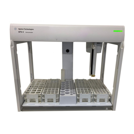
Figure 1 Front view of the Agilent SPS 4 1 Spill Tray The spill tray sits on the bottom base bars of the Agilent SPS 4, and catches any spills. 2 Rack Location Mat The rack location mat sits on top of the spill tray, and positions the sample racks, standards rack and fixed wash reservoir. - Page 18 The indicator lights change to red when an error occurs in the equipment. There are 4 error indicators and these illuminate in different combinations to indicate a specific error condition. See "Error Agilent SPS 4 Autosampler User’s Guide...
-
Page 19: Rear View
The power switch turns on/off the Agilent SPS 4. Power is ON. Power is OFF. When the Agilent SPS 4 is turned on, the initialization sequence runs to check the basic functions and set the probe position. If there are no errors, the power/error indicator turns green. - Page 20 Agilent instrument or in some cases, to the instrument directly, using the furnished standard USB Type A to B cable. The Agilent SPS 4 will appear as a virtual COM port under Windows. 4 Auxiliary Communications Port (AUX) The auxiliary communications port provides an RS485 interface, but is not used in current Agilent software.
-
Page 21: Intended Use
Introduction Intended Use The Agilent SPS 4 is designed to automate the presentation of liquid samples, drawn from tubes held in racks loaded on the rack location mat, to the instrument for analysis. The Agilent SPS 4 is controlled through software commands sent via a USB interface. -
Page 22: Specifications
Introduction Specifications Environmental Your Agilent SPS 4 is designed for indoor use only. It is suitable for Installation Category II and Pollution Degree 2. The site should be selected to avoid dusty or corrosive atmospheres. Table 1 Suitable environmental conditions for the Agilent SPS 4... -
Page 23: Weights And Dimensions
18.6 kg (41.0 lbs). To avoid injury to personnel or damage to equipment, always use a fork lift or other suitable lifting device when moving the instrument. If a fork lift is not available, the Agilent SPS 4 will need to be lifted by two people. Table 3... - Page 24 Host: USB (5 VDC, 100 mA Max.) – Auxiliary: RS485 (-8 12.5 VDC, 250 mA Max.) [not used] Host Interface Port USB (Type A to Type B) Auxiliary Port (not used) RS485 (DB9 Male connector) Agilent SPS 4 Autosampler User’s Guide...
-
Page 25: Options And Accessories
Introduction Options and Accessories The available options and accessories for the Agilent SPS 4 are listed in Table Table 5 Available options and accessories Description Single port fixed wash reservoir kit Standard cover kit Sample probe kit, 0.25 mm ID Sample probe kit, 0.5 mm ID... - Page 26 LDPE Bottle 250 ml Narrow Mouth 250/pk Polypropylene test tubes, 17 mm OD, 16.5 mL, 1000/pk Centrifuge, screw capped, 30 mm OD, 50 mL, 500/pk polypropylene Drainage Tank, polyethylene, 4 liter Drainage Tank,10 liter 96-well Plates, 0.5 ml, PP 10pk Agilent SPS 4 Autosampler User’s Guide...
- Page 27 Allows 16 mm OD tubes to be used in 60 position rack (Qty 2 recommended per rack) Rack overlay for 40 position sample rack Allows 18 mm OD tubes to be used in 40 position rack (Qty 2 recommended per rack) Agilent SPS 4 Autosampler User’s Guide...
- Page 28 Introduction This page is intentionally left blank. Agilent SPS 4 Autosampler User’s Guide...
-
Page 29: Installation
Setting up the Instrument Controlling Software for SPS 4 Notes on Lifting the Autosampler The Agilent SPS 4 autosampler is designed to be completely self- installable. Instructions for setting up the autosampler are included in this manual. For more information on setting up the instrument software, refer to the documents provided with the instrument or the instrument's help. -
Page 30: Installation Procedure
Connecting the Power and the Communications Cable Confirming the Operation Setting up the Instrument Controlling Software for SPS 4 Position the autosampler so that it is easy to access the mains power switch on the WA R N I N G wall outlet or to remove the power cord from the autosampler or wall outlet. - Page 31 Installation X-Axis Front Z-Axis T-Axis Left Right Rear Figure 3 Autosampler orientation Agilent SPS 4 Autosampler User’s Guide...
-
Page 32: Bench Requirements
Danger to hands and feet. When unpacked the autosampler is heavy. To avoid injury WA R N I N G to personnel or damage to equipment, always use at least two people to lift the autosampler into position. Agilent SPS 4 Autosampler User’s Guide... - Page 33 • Power supply cable including an AC adapter (as appropriate for your location) ** • Tubing (including 3- bridge pump tubing) * *: These items are packed in an accessory kit box. **: This item is packed in another box. Agilent SPS 4 Autosampler User’s Guide...
-
Page 34: Installing The Cover Kit
To prevent you and the instrument from earthquake damage, it is recommended to WA R N I N G secure the main body of the autosampler on your bench before this step. For how to secure, see “Preventing Earthquake Damage” on Page 94. Agilent SPS 4 Autosampler User’s Guide... - Page 35 If rinse fluid, sample fluid, standard fluid or other liquids spill on the spill tray, wipe WA R N I N G up immediately. These liquids may corrode the instruments. Highly alkaline or acidic fluids can injure the skin and mucus membranes. Exercise caution when handling these fluids. Agilent SPS 4 Autosampler User’s Guide...
-
Page 36: Installing The Rack Location Mat
Figure 7 Rack location mat fitted to the left end frame 3 Ensure that the slot for the fixed wash reservoir is located at the rear of the unit when installing the rack location mat. Agilent SPS 4 Autosampler User’s Guide... -
Page 37: Installing The Wash Reservoir
1 Put the base of the fixed wash reservoir into the locating hole and twist it clockwise 60 degrees so it locks into position. The nipples on the fixed wash reservoir should be facing toward the rear of the Agilent SPS 4 Autosampler User’s Guide... - Page 38 (see Figure 5 Re- fit the rack location mat to the unit. Figure 9 Feeding tubing through rubber grommet on rear cover (if fitted) Agilent SPS 4 Autosampler User’s Guide...
-
Page 39: Installing The Standards Rack
2 Align the feet from the standards rack with the holes in the rack location mat. Press down on the rack to ensure it is correctly located and the bottom of the standards rack is sitting flush with the rack location mat. Agilent SPS 4 Autosampler User’s Guide... -
Page 40: Installing The Sample Racks
2 Align the feet from each sample rack with the holes in the rack location mat. Press down on the rack to ensure it is correctly located and the bottom of the sample rack is sitting flush with the rack location mat. Agilent SPS 4 Autosampler User’s Guide... - Page 41 For example, a 60 position rack needs vials that OD is within 16.1 mm to 16.5 mm at a height of 60 mm. If the diameter is less than or equal to 16.1 mm, you may be able to use them with optional rack overlays. Agilent SPS 4 Autosampler User’s Guide...
-
Page 42: Fitting The Sample Probe
4 Place the mount nut from the sample probe on top of the accessories plate with the recessed edge facing up and the holes approximately aligned. 5 Move the Z- axis slide down stopping just above mount nut sitting on the accessories plate. Agilent SPS 4 Autosampler User’s Guide... - Page 43 Do not use the tube restraint for pre- formed sample probes. It is only N O T E used for non pre- formed sample probes. Tube Anchor Grommet Cable tie tubing through the eyelet on bottom of housing Colored Markers Figure 14 Routing the sample line tubing Agilent SPS 4 Autosampler User’s Guide...
-
Page 44: Fitting The Wash Pump Tubing
The third channel can also be used to pump the used rinse solution to the waste container (optional). The wash pump is controlled by the instrument control software and rotates clockwise. Agilent SPS 4 Autosampler User’s Guide... - Page 45 In addition it may be necessary to disconnect the power cable, interface cable, sample line, inlet line to the wash pump or the drain line from the fixed wash reservoir depending on the distance moved. Agilent SPS 4 Autosampler User’s Guide...
-
Page 46: Two Drain Arrangements
(or two channels for dual port wash reservoir) of the peristaltic pump to the inlet of the wash reservoir. It then drains out from the outlet of the wash reservoir into the waste container through other channel of Agilent SPS 4 Autosampler User’s Guide... -
Page 47: Loading Wash Pump Tubing
6 Route the inlet line of the wash pump tubing through the tube anchor clip(s) and connect this to the suction line from the rinse solution reservoir. Agilent SPS 4 Autosampler User’s Guide... -
Page 48: Pressure Plate Adjustment
Connecting the Power and the Communications Cable Before connecting any part of the autosampler to the mains power supply, check you have the correct power supply. The power requirements are given in “Power” on Page 22. Agilent SPS 4 Autosampler User’s Guide... - Page 49 2 Connect the other end of the USB cable to a USB port on your computer or instrument. 3 Fix the USB cable and the power cable using the cable ducting on the rear column of the autosampler. Agilent SPS 4 Autosampler User’s Guide...
-
Page 50: Confirming The Operation
5 The probe arm moves to the four corners of the rack location mat. 6 The probe arm stops above the fixed wash reservoir. Setting up the Instrument Controlling Software for SPS 4 You need to set up your instrument control software in order to set parameters such as the rack configuration, the communication port, probe depth, and so on. -
Page 51: Notes On Lifting The Autosampler
Figure 18 Lifting positions for removing the autosampler The autosampler should never be carried by the probe carriage or the wash pump C A U T I O N tubing ducting. Agilent SPS 4 Autosampler User’s Guide... - Page 52 Installation This page is intentionally left blank. Agilent SPS 4 Autosampler User’s Guide...
- Page 53 Agilent SPS 4 Autosampler User’s Guide Operation Starting up the Autosampler Shutting Down the Autosampler Flushing the Wash Reservoir and Flow Path Software Control Agilent Technologies...
-
Page 54: Operation
Ensure there are no air bubbles visible in the rinse uptake tubing before you start using the autosampler. Agilent SPS 4 Autosampler User’s Guide... -
Page 55: Shutting Down The Autosampler
1 Insert the rinse uptake tubing into a deionized water source. If you are flushing the wash system during initial startup, first use a 2% nitric acid solution N O T E as the rinse agent, followed by deionized water. Agilent SPS 4 Autosampler User’s Guide... -
Page 56: Software Control
All operations of the autosampler can be controlled by commands from the instrument control software. For details on how the software interface interacts with the autosampler, consult the relevant section of the manuals or instrument Help. Agilent SPS 4 Autosampler User’s Guide... -
Page 57: Maintenance
Agilent SPS 4 Autosampler User’s Guide Maintenance Routine Maintenance Cleaning Replacing the Wash Pump Tubing Lubrication Service Spare Parts The Agilent SPS 4 autosampler has been designed for low maintenance and there are no user adjustments necessary under normal operating conditions. Agilent Technologies... -
Page 58: Routine Maintenance
The exterior surfaces of the autosampler, spill tray, rack location mat and accessories should be kept clean. All cleaning should be done with a soft, lint- free cloth. If necessary, this cloth can be dampened with water or a mild detergent. Agilent SPS 4 Autosampler User’s Guide... -
Page 59: Replacing The Wash Pump Tubing
Because of the operating nature of the wash pump, the tubing will probably be the most frequently replaced item on the Agilent SPS 4 autosampler. If you use strong bases, acids, or solvents as rinsing agents, the tubing may break down rapidly. -
Page 60: Lubrication
For ordering information of the consumable spare parts, see the Agilent website at www.agilent.com. Only use Agilent spare parts with your autosampler. N O T E Table 6 Consumable spare parts Description Standard rack location mat Spill tray Tube anchor Cable ducting Agilent SPS 4 Autosampler User’s Guide... - Page 61 Nipple, PVDF, 5 mm ID, FWR Nipple, PVDF, 2.5 mm ID, FWR Tubing, PVC, 8 mm OD x 5 mm ID Tubing, 2.5 mm ID 2 meter length Barb connector 2.5 mm - 1.5 mm Agilent SPS 4 Autosampler User’s Guide...
- Page 62 Maintenance This page is intentionally left blank. Agilent SPS 4 Autosampler User’s Guide...
-
Page 63: Troubleshooting
Error Indicator Codes Initialization Problems Probing Problems Communication Problems If your Agilent SPS 4 Autosampler is not operating correctly, it can be difficult to determine whether the condition is caused by the autosampler, the instrument control software or communication between the two. -
Page 64: Troubleshooting Guide
Troubleshooting Troubleshooting Guide The Agilent SPS 4 is equipped with diagnostic tools such as power/error indicator and initialization sequence on startup to assist in identifying the problems. Power/Error Indicator: Provides useful information on the error state of the autosampler. Initialization... -
Page 65: Power Supply Problems
2 Visually check the Agilent SPS 4 and power lead for any electrical damage. 3 If the Agilent SPS 4 still fails to initialize contact your Agilent customer support representative. Operating State Problems The power/error indicator is used to identify the operating state of the Agilent SPS 4: •... -
Page 66: Error Indicator Codes
The power/error indicator on the front panel is a line of four LEDs. These LEDs illuminate RED when an error has occurred with the Agilent SPS 4. The red illumination of these LEDs indicates a binary error code to assist you in identifying the possible cause of the incorrect functioning of the unit. - Page 67 X-axis movement detected without the Refer to “Probing motor being commanded to move. Problems” on Page 69 for details. Theta-axis movement detected without Refer to “Probing the motor being commanded to move. Problems” on Page 69 for details. Agilent SPS 4 Autosampler User’s Guide...
-
Page 68: Initialization Problems
Table 7 for the error indicator codes. Check the Agilent SPS 4 by doing the following: 1 Turn the power off and move each axis manually until they stop and determine if there is any mechanical obstruction preventing full travel. -
Page 69: Probing Problems
Probing Problems Probe Arm Jam A probe arm jam is indicated when the Agilent SPS 4 cannot complete its instructed move. This could be caused by: • The probe arm hitting an obstacle or the sample line is restricted while moving into position. -
Page 70: Communication Problems
2 Disconnect the USB cable and initialize the autosampler to ensure that it is in a working state. To do this, turn off the power switch, wait 10 seconds and then turn the power switch on. If the Agilent SPS 4 completes the initialization sequence with no error indicators, then this usually indicates that the autosampler is working fine. - Page 71 User calibration allows for minor adjustments to center the sample probe. This chapter provides instructions on performing user calibration for the Agilent SPS 4 autosampler using the Calibration Wizard software. If centering for the sample probe on your autosampler is...
-
Page 72: Running The Calibration Wizard
There are four calibration points, one for each corner in the movement range of the probe arm. At each calibration point, adjust the probe position. The following shows the Calibration Wizard window. Figure 19 Calibration Wizard Window Agilent SPS 4 Autosampler User’s Guide... - Page 73 1 mm for larger adjustments. Capture button: Stores the calibration data at each calibration point. Press this when the probe is centered in a good position in the sample. Agilent SPS 4 Autosampler User’s Guide...
-
Page 74: Performing User Calibration
Com Port field shows the information on the rack layout specific to your autosampler. Ensure that the sample rack types displayed on the screen correspond to those loaded into their respective positions on the rack location mat. Agilent SPS 4 Autosampler User’s Guide... - Page 75 Adjust the XY position to the middle of the well using the arrow buttons. c When the position of the probe is centered in the sample well, click Capture. The indicator next to the “Rear Left” button changes from orange to green. Agilent SPS 4 Autosampler User’s Guide...
- Page 76 Adjust the XY position to the middle of the well using the arrow buttons. c When the position of the probe is centered in the sample well, click Capture. The indicator next to the “Rear Right” button changes from orange to green. Agilent SPS 4 Autosampler User’s Guide...
- Page 77 Adjust the XY position to the middle of the well using the arrow buttons. c When the position of the probe is centered in the sample well, click Capture. The indicator next to the “Front Left” button changes from orange to green. Agilent SPS 4 Autosampler User’s Guide...
- Page 78 Adjust the XY position to the middle of the well using the arrow buttons. c When the position of the probe is centered in the sample well, click Capture. The indicator next to the “Front Right” button changes from orange to green. Agilent SPS 4 Autosampler User’s Guide...
-
Page 79: Error List
Check that the power is on, and no error lights are illuminated. Also confirm the USB connection and the COM port setting in the instrument control software. If the problem still remains unresolved, contact your Agilent customer support representative. Agilent SPS 4 Autosampler User’s Guide... - Page 80 In this case, any problems you are having are unlikely to be caused by alignment. Contact your Agilent customer support representative. Agilent SPS 4 Autosampler User’s Guide...
-
Page 81: Appendices
Agilent SPS 4 Autosampler User’s Guide Appendices Installing the Cover Kit Preventing Earthquake Damage Default Rinse Materials Agilent Technologies... -
Page 82: Installing The Cover Kit
Appendices Installing the Cover Kit Introduction The Autosampler Cover covers an Agilent SPS 4 autosampler and can be used to: • Help protect the operator and the laboratory environment from sample vapors. • Protect the samples from drafts, dust and possible airborne contamination. -
Page 83: Tools Required
Do not slide the clear panels across the bench or against each other to avoid C A U T I O N scratching. The autosampler cover kit is supplied as an easy- to- fit kit and consists of the following components: Agilent SPS 4 Autosampler User’s Guide... -
Page 84: Installing Your Autosampler Cover
1 Remove the cable ducting that clips onto the rear of the end frame to hold the power and communication cables in place. 2 Remove the Spill Tray and the Rack Location Mat. 3 Lay the unit forward onto its front while supporting the probe arm. Agilent SPS 4 Autosampler User’s Guide... - Page 85 Grommet to right side Remove cable ducting 5 Lift the top of the end cover up over the edge of the chassis as shown below. Lift cover up over this edge Agilent SPS 4 Autosampler User’s Guide...
- Page 86 7 Fasten the Rear Cover to the wash pump tubing ducting using the plastic screw and nut supplied as shown below. Tighten by hand only. Fasten using screw and nut Agilent SPS 4 Autosampler User’s Guide...
- Page 87 Flare the bottom end of the cable ducting and fit to bottom of end frame cover slot as shown below. b Move along the ducting pushing into place so that it clips over the outer edge of the end frame as shown below. Agilent SPS 4 Autosampler User’s Guide...
- Page 88 10 Re- fit the Spill Tray. 11 Re- fit the Rack Location Mat, carefully feeding the fixed wash reservoir tubing through the grommet in the rear cover. Agilent SPS 4 Autosampler User’s Guide...
- Page 89 The side cover is pushed into the recesses of the end frame from the inside and slides down to lock in place. 3 Fit the other side cover (blank) to the other end of the autosampler using the same process. Agilent SPS 4 Autosampler User’s Guide...
- Page 90 Guide the front cover into the slots at the top of the end frames as shown below. 2 Supporting the front cover underneath, gently guide the front cover down until it sits on the rack location mat. Agilent SPS 4 Autosampler User’s Guide...
-
Page 91: Door Operation
The door is held in the open position by a step in the end frame slots. Do not remove samples racks or standard racks or vials while the autosampler is WA R N I N G operating. Step in end frame slots Agilent SPS 4 Autosampler User’s Guide... -
Page 92: Connections
Whenever such liquids are present, the atmospheric contents of the sample cover must be extracted continuously at a minimum rate of 350 liters per minute. Corrosive samples and standards should be removed from the autosampler once analysis is completed. Agilent SPS 4 Autosampler User’s Guide... - Page 93 Any failure in the extraction system could present a fire hazard. Failure to provide adequate extraction at all times will potentially concentrate the C A U T I O N corrosive fumes and damage the autosampler. This damage is not covered by warranty. Agilent SPS 4 Autosampler User’s Guide...
- Page 94 If necessary, prepare seismic brackets similar to those in figure below and secure the brackets. Seismic brackets are not supplied by Agilent. Prepare these items separately. N O T E 8 mm Bracket (example) 188 mm 75 mm Agilent SPS 4 Autosampler User’s Guide...
- Page 95 Solvaflex (Solva) Barb connector 2.5mm-1.5mm Polypropylene (PP) Tubing, 2.5mm ID Nipple, PP, 2.5mm ID, FWR Single port rinse station PP main part Nipple, PVDF, 5mm ID, FWR Polyvinylidene fluoride (PVDF) Tubing, PVC, 8mm x 5mm Agilent SPS 4 Autosampler User’s Guide...
- Page 96 Appendices This page is intentionally left blank. Agilent SPS 4 Autosampler User’s Guide...
- Page 98 In This Book This book explains the procedures necessary to use the Agilent SPS 4 Autosampler to enhance sample analysis. © Agilent Technologies, Inc. 2015 Printed in Malaysia Revision A, May 2015 *G8410-90000* G8410-90000 Agilent Technologies...