Table of Contents
Advertisement
Quick Links
Advertisement
Table of Contents
Troubleshooting

Related Manuals for Fronius TPS/i Robotics TWIN Push


Summary of Contents for Fronius TPS/i Robotics TWIN Push
- Page 1 Perfect Welding / Perfect Charging / / Solar Energy Operating Instructions Welding System TPS/i Robotics TWIN Push MIG/MAG robot welding system 42,0426,0277,EA 006-30012020 Fronius prints on elemental chlorine free paper (ECF) sourced from certified sustainable forests (FSC).
-
Page 3: Table Of Contents
Table of contents Safety Instructions ............................. Explanation of Safety Instructions......................General ..............................Intended Use............................Environmental Conditions ........................Obligations of the Operating Company....................Obligations of Personnel........................Grid Connection ............................ Personal Protection and Protection of Others..................Danger from toxic gases and vapors ....................Danger from Flying Sparks ........................ - Page 4 Clamp System Scope of Supply ......................Robot welding torch ........................... Safety..............................Robot welding torch ..........................Tilt angle of the contact tips ......................... Welding Technology Aspects Welding Technology Aspects........................Protective gas shields for TWIN welding processes ................Conducting R/L comparison........................Work angle of the welding torch......................Stick out ..............................
- Page 5 Checking the function of the torch body coupling ................. Connecting the Protective Gas Shield and Grounding Cable ..............Connecting Protective Gas Shield ......................Connect the grounding cable ........................ Preparing TWIN Wirefeeder for Operation....................General ..............................Inserting/Changing Feed Rollers ......................Connecting Wirefeeding Hoses ......................Threading the Wire Electrode .......................
-
Page 7: Safety Instructions
Safety Instructions Explanation of DANGER! Safety Instruc- tions Indicates an immediate danger. ► Death or serious injury may result if appropriate precautions are not taken. WARNING! Indicates a possibly dangerous situation. ► Death or serious injury may result if appropriate precautions are not taken. CAUTION! Indicates a situation where damage or injury could occur. -
Page 8: Environmental Conditions
The device is intended exclusively for the welding process specified on the rating plate. Utilization for any other purpose, or in any other manner, shall be deemed to be "not in ac- cordance with the intended purpose." The manufacturer is not responsible for any damage resulting from improper use. -
Page 9: Personal Protection And Protection Of Others
This may affect a number of device types in terms of: connection restrictions criteria regarding maximum permissible grid impedance criteria regarding the minimum required short-circuit power both at the interface with the public grid See technical data In this case, the operator or the person using the device should check whether or not the device is allowed to be connected, where appropriate through discussion with the power supply company. -
Page 10: Danger From Flying Sparks
Take the following precautionary measures for fumes and harmful gases: Do not breathe them in. Extract them from the work area using appropriate equipment. Ensure that there is a sufficient supply of fresh air. Ensure that there is a ventilation flow rate of at least 20 m³... -
Page 11: Stray Welding Currents
Ensure suitable personal protection with dry temporary backing or cover with sufficient in- sulation against the ground potential. The temporary backing or cover must completely cover the entire area between the body and the ground potential. All cables and leads must be secured, undamaged, insulated, and adequately dimen- sioned. -
Page 12: Emc Device Classifications
Observe the following when using electrical distributors, double-headed retainers, etc.: Even the electrode of the welding torch/electrode holder not in use carries electric poten- tial. Ensure that there is sufficient insulation when the unused welding torch/electrode hold- er is stored. In automated MIG/MAG applications, only guide the wire electrode from the welding wire drum, large spool or wirespool to the wirefeeder with insulation. -
Page 13: Emf Measures
EMF measures Electromagnetic fields may cause health problems that are not yet known: Effects on the health of persons close by, e.g., those with pacemakers and hearing aids Persons with pacemakers must seek advice from their doctor before staying in the im- mediate vicinity of the device and the welding process Keep distances between welding cables and the head/torso of the welder as large as possible for safety reasons... -
Page 14: Requirement For The Shielding Gas
In the event of crane attachment of the wirefeeder during welding, always use a suitable, insulating wirefeeder hoisting attachment (MIG/MAG and TIG devices). If the device is equipped with a carrier belt or handle, then this is used exclusively for trans- port by hand. -
Page 15: Safety Measures At The Setup Location And During Transport
Shielding gas is colorless and odorless and may suppress the oxygen in the ambient air in the event of leakage. Ensure there is a sufficient supply of fresh air with a ventilation flow rate of at least 20 m³ per hour. Please observe the safety and maintenance information for the shielding gas cylinder or the main gas supply. -
Page 16: Maintenance And Repair
Only the original coolant from the manufacturer is suitable for use in our devices due to its properties (electrical conductivity, anti-freeze, material compatibility, flammability, etc.) Only use appropriate original coolant from the manufacturer. Do not mix original coolant from the manufacturer with other coolants. Only connect system components from the manufacturer to the cooling unit circuit. -
Page 17: Safety Symbols
(e.g. relevant product standards of the EN 60974 se- ries). Fronius International GmbH declares that the device complies with Directive 2014/53/EU. The full text of the EU Declaration of Conformity is available on the following website: http:/ /www.fronius.com... -
Page 19: General Information
General Information... -
Page 21: General
General Application areas TWIN welding systems are used exclusively with automated MIG/MAG applications, e.g.: in rail vehicle manufacturing for longitudinal seams and profiles in shipbuilding for fillet welds and profiles in vehicle manufacturing for lap joints and wheel rim welding in automotive engineering in container construction for butt welds, longitudinal seams, lap joints and circumfer- ential welds... -
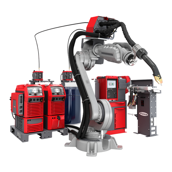
Page 22: System Overview
System overview (13) (14) (16) (15) (10) (11) (17) (12) (19) (18) Welding wire drum (10) HP 95i CON /G /10 m intercon- necting hosepack Wirefeeding hoses (11) HP 95i CON /W /10 m intercon- Robot controls necting hosepack Connection cable from robot con- (12) Robot trols to RI FB Pro/i TWIN Control-... -
Page 23: Requirements
1 x HP 95i CON /W /xx m 1 x HP 95i CON /G /xx m 2 x wirefeeding hose (max. 3 m) or Fronius PowerLiner (max. 10 m) 2 x power source TPS 400i Pulse / 500i Pulse / 600i Pulse TPS 400i / 500i / 600i with Welding Package Pulse + firmware official_TPSi_2.2.3-20789.15069.ffw and above... -
Page 24: Dimensioning Of The Robot
Dimensioning of Observe the following points during the dimensioning of the robot: the robot The torch holder on the robot must be designed to be stable. The CrashBox must be designed accordingly. The TWIN hosepack must be considered when dimensioning the robot. The wirefeeding hoses must be laid using balancers in the robot cell. -
Page 25: Ground Connection
Ground connec- Use a separate grounding cable for each power source: tion Separate grounding cables Shared grounding cable, grounding bridge Grounding cable with bifilar winding Grounding cable coiled Further information on connecting the grounding cable can be found from page 81. Note about the NOTE! wirefeed... -
Page 26: Functional Principle
Functional principle Operating Princi- Two wire electrodes (4) and (5) are welded in a weld pool in a shielding gas environ- ment. The welding process is carried out via two independent power sources (1) and (2). The power sources are synchronized by the TWIN Controller. The wirefeed is carried out via a wirefeeder (3) with two drive units. -
Page 27: Wf 30I R /Twin
Intended Use The device is intended exclusively for wirefeeding in automated MIG/MAG welding in com- bination with Fronius system components. Any other use does not constitute proper use. The manufacturer accepts no liability for any damage resulting from improper use. -
Page 28: Warning Notices On The Device
The safety symbols warn against oper- ating the equipment incorrectly, as this may result in serious injury and damage to property. Part No.: www.fronius.com Ser.No.: IEC 60 974-5/-10 Cl.A IP 23 60 V 1.2 A... - Page 29 Dispose of old devices in accordance with safety rules and not in normal domestic waste. Keep hands, hair, loose clothing, and tools away from moving parts, such as: Do not reach into rotating gears of the wire drive or into rotating drive parts. Covers and side parts must only be opened/removed during maintenance and repair work.
-
Page 30: Description Of Warning Notices On The Device
Description of On certain device versions, warning notices are attached to the device. Warning Notices on the Device The arrangement of the symbols may vary. Warning! Watch Out! There are possible hazards as shown by the symbols. Drive rolls can injure fingers. Welding wire and drive parts are at welding voltage during operation Keep hands and metal objects away. - Page 31 Welding sparks can cause explosion or fire. Keep flammables away from welding. Don’t weld near flammables. Welding sparks can cause fires.Have a fire extinguisher nearby and have a watch- person ready to use it. Do not weld on drums or any closed containers. Arc rays can burn eyes and injure skin.
-
Page 32: Interconnecting Hosepack
Interconnecting hosepack Interconnecting hosepack G = gas-cooled interconnecting hosepack, W = water-cooled interconnecting hosepack The interconnecting hosepacks connect the power sources to the TWIN wirefeeder. In TWIN welding systems, one water-cooled and one gas-cooled interconnecting hosepack are used. -
Page 33: Torch Hosepack
Torch hosepack General The torch hosepack is designed for water-cooled TWIN robot applications. It connects the TWIN wirefeeder with the TWIN welding torch. Scope of supply Not included in the scope of supply: Inner liners Inlet nozzles Hosepack MHP 2x500i R/W/FSC... -
Page 34: Crashbox
CrashBox General The CrashBox /i is a protection device for the torch body and the torch body coupling. In the event of a collision, the CrashBox emits a signal to the robot controls, which causes the robot controls to stop the robot immediately. -
Page 35: Scope Of Supply
Scope of supply CrashBox /i holder 1-ear clamp * Locking ring, 2-part * Bellows Cylinder head screws M4 x 16 mm Magnetic ring Mounted on bellows (4) on delivery (2)(3) (5)(6) CrashBox /i XXL scope of supply NOTE! Do not assemble the CrashBox /i holder (1) and magnetic ring (6) before installing on the robot. -
Page 36: Robot Welding Torch
Robot welding torch Safety CAUTION! Burning hazard due to hot torch body, hot torch body coupling as well as other hot welding torch components. Before starting work on the torch body, the torch body coupling and all other welding torch components: ►... -
Page 37: Tilt Angle Of The Contact Tips
Tilt angle of the Depending on the application, different tilt contact tips angles of the contact tips toward each other of 4°, 8° and 11.5° are available for the TWIN welding torches. Corresponding assembly components are required for each angle: 4°... -
Page 39: Welding Technology Aspects
Welding Technology Aspects... -
Page 41: Welding Technology Aspects
Welding Technology Aspects Protective gas Material Protective gas shield shields for TWIN Non-alloyed and low-alloy steels ArCO , ArO2 and ArCO mixtures welding process- CrNi steels, high-alloy steels ArCO mixtures, proportion of active gas max. 2.5% mixtures, proportion of active gas max. 3% ArCO He mixtures, proportion of active gas max. -
Page 42: Work Angle Of The Welding Torch
Work angle of the Select the work angle of the welding torch welding torch so that the lead wire electrode (= wire elec- trode of the lead power source) is in a neu- tral to slightly leading position. approx. 90–100° for steel applications approx. -
Page 43: Twin Characteristics
TWIN Characteristics General Only PMC TWIN characteristics with the following properties are available for the TWIN welding process: Universal Multi arc The same TWIN characteristic must be selected on both process lines. Prerequisites for using a PMC TWIN characteristic: Pulse welding package on both power sources Both power sources must be connected to the TWIN Controller. -
Page 44: Twin Welding Processes
TWIN Welding Processes TWIN welding Lead wire electrode Trail wire electrode processes - over- (= lead power source) (= trail power source) view Welding direction PMC TWIN PMC TWIN PCS TWIN PCS TWIN Single wire (Pulse*/Standard*/PMC*/LSC*) Single wire (Pulse*/Standard*/PMC*/LSC*) * activation required IMPORTANT! There are no TWIN characteristics available for Pulse or Standard welding processes. -
Page 45: Pmc Twin / Pmc Twin
PMC TWIN / PMC TWIN I (A) t (s) > I Welding current time curves and schematic representation of the material transition P = phase shift Time coordination of the power sources The PMC processes of the two process lines are synchronized with one another. This guarantees a stable, consistent tandem welding process. -
Page 46: Pcs Twin / Pcs Twin
PCS TWIN / PCS TWIN I (A) t (s) Welding current time curves and schematic representation of the material transition PCS TWIN characteristics are predominantly used in order to weld with a modified spray arc at the lead wire electrode and a pulsed arc at the trail wire electrode. Advantages: high penetration by the standard arc of the lead wire electrode large seam cross sections possible... -
Page 47: Single Wire (With A Twin Welding Torch):Pmc/Pulse/Lsc/Standard
Single wire (with Welding current time curves and schematic representation of the material transition a TWIN welding torch): PMC/Pulse/LSC/ Standard I (A) I (A) t (s) t (s) PMC/Pulse - lead power source LSC/Standard - lead power source I (A) I (A) t (s) t (s) - Page 48 Single wire welding is used in a TWIN welding system: when welding very tight radii when welding in difficult positions and restricted positions to fill up end-craters if there has been a switch to a single welding torch on the welding torch change station...
-
Page 49: Twin Process Parameters
TWIN Process Parameters TWIN process pa- The following TWIN process parameters are available at the power sources in TWIN mode rameters under Process parameters / TWIN process control: Wirefeeder Arc length correction Pulse/dynamic correction Penetration stabilizer Arc length stabilizer Pulse synchronization ratio * Lead/trail phase shift * Trail ignition delay * The following sections contain a detailed description of special process parameters... -
Page 50: Lead/Trail Phase Shift
Lead/trail phase Adjustment range: auto, 0 - 95% shift Factory setting: auto Lead/trail phase shift enables the time of droplet detachment to be freely selected for the trail arc. As the trail droplet detachment does not have to take place in the quiescent cur- rent phase of the lead arc, a magnetic arc blow between the two arcs can be counteracted. -
Page 51: Trail Ignition Delay
Trail ignition de- When this function is activated, the ignition point of the trail arc always depends on the present phase of the lead arc. The start parameters of the trail arc are automatically adapt- ed to the prevailing conditions of the lead arc. The trail arc starts without contact and considerably more smoothly. -
Page 53: Operating Controls, Connections And Mechanical Components
Operating controls, connections and mechanical components... -
Page 55: Wf 30I R /Twin: Operating Controls, Connections, And Mechanical Components
WF 30i R /TWIN: Operating Controls, Connections, and Mechanical Components Safety WARNING! Danger due to incorrect operation. Serious personal injury and damage to property may result. ► All functions described may only be used by trained personnel. ► Read and understand this document in full. ►... -
Page 56: Wirefeeder Side
(10) Coolant supply connection (blue) For connecting the coolant hose from the torch hosepack (11) Coolant return connection (red) For connecting the coolant hose from the torch hosepack (12) Compressed air connection IN OPT/i WF gas purging option 16 bar Wirefeeder Side (17) (5) (6) -
Page 57: Function Of The Gas-Test, Wire-Return And Wire Threading Buttons
(13) 4-roller drive 2 (14) Clamping lever 2 for adjusting the contact pressure of the feed rollers (15) Protective cover of the 4-roller drive 2 (16) Welding torch clamping lever 2 (17) Cover Function of the Gas-test button Gas-Test, Wire- Return and Wire After pressing the gas-test button, gas is released for 30 s. -
Page 58: Wirefeeder Rear
Wire-threading button There are two options available for the wire threading: Option 1 Thread the wire electrode at the preset feeder inching speed: Press and hold the wire-threading button After pressing the wire-threading button, the wire electrode will be threaded in by 1 mm (0.039 in.) After a brief pause, the wirefeeder continues threading in the wire electrode –... - Page 59 Dummy cover Dummy cover...
-
Page 60: Interconnecting Hosepack
Interconnecting hosepack Interconnecting SpeedNet cable Hosepack—Con- Coolant hoses nections Protective gas shield hose Power cable W = water-cooled interconnecting hosepack G = gas-cooled interconnecting hosepack... -
Page 61: Installation And Startup
Installation and Startup... -
Page 63: Safety-Installation And Commissioning
Safety—Installation and Commissioning Safety WARNING! Incorrect operation and incorrectly performed work can cause serious injury and damage to property. ► All work listed in this document may only be performed by trained specialist personnel. ► All functions described in this document may only be used by trained specialist person- nel. -
Page 64: Insulated Guiding Of The Wire Electrode To The Wirefeeder
Insulated Guiding WARNING! of the Wire Elec- trode to the Wire- Risk of injury and property damage, as well as impairment of the welding result, due feeder to ground fault or earth leakage of a non-insulated wire electrode. ► In automated applications, only guide the wire electrode from the welding wire drum, large spool or wirespool to the wirefeeder with insulation (for example using a wirefeed- ing hose). -
Page 65: Before Installation And Initial Operation
Before installation and initial operation Setup regulations WARNING! Toppling or falling devices can be deadly. ► Set up all system components, upright brackets and trolleys so that they are stable on a flat and solid surface. The wirefeeder has been tested according to protection class IP 23. This means: Protection against the penetration of solid foreign bodies with a diameter of more than 12.5 mm (0.49 in.) Protection against spraywater at any angle up to 60°... - Page 66 Installing the CrashBox, torch hosepack and TWIN welding torch Mount the robot flange and CrashBox on the robot Insert the inner liners into the torch hosepack Install the clamp on the CrashBox Insert the torch hosepack into the clamp Connect CrashBox cable Connect torch hosepack to the wirefeeder Insert the inner liners into the TWIN welding torch Install the torch body coupling...
-
Page 67: Install Twin Wirefeeder And Accessories On The Robot
Install TWIN Wirefeeder and Accessories on the Ro- Install Wirefeeder on the Robot Installation of the wirefeeder holder depends on the ro- 7 Allen screws 6 mm bot. Follow the Installation Instructions for the wirefee- tightening torque = 20 Nm der holder! 6 Allen screws 6 mm + NL wedge-locking washers 2 Allen screws 5 mm + NL wedge-locking washers... -
Page 68: Install Side Holders For The Interconnecting Hosepacks On The Robot
Push in the hose clamps until they audibly engage Install side hold- ers for the inter- connecting hosepacks on the robot Installation of the side holder depends on the robot. Follow the Installation Instructions! -
Page 69: Lay, Install And Connect Interconnecting Hosepacks
Lay, Install and Connect Interconnecting Hosepacks Connect intercon- NOTE! necting hose- packs to the If the interconnecting hosepack is laid incorrectly it can have a significant influence wirefeeder on the welding results, a stable welding process is not guaranteed! ► As far as possible, maintain a distance of 30 - 50 cm between the two interconnecting hosepacks. -
Page 70: Connect The Interconnecting Hosepacks To The Power Source, Cooling Unit And Twin Controller
Connect the inter- IMPORTANT! When connecting the interconnecting hosepacks, observe marks 1 and 2 connecting hose- on the interconnecting hosepacks and on the power sources: packs to the 1 = water-cooled interconnecting hosepack power source, 2 = gas-cooled interconnecting hosepack cooling unit and TWIN Controller NOTE! -
Page 71: Connect Twin Controller
Connect TWIN Controller Connect the TWIN Controller with Connecting power source to the TWIN Con- the Power Sourc- troller via SpeedNet cable es and Connect Interconnecting Hosepack TPSi 1 = power source 1 TPSi 2 = power source 2 HP CON 1 = interconnecting hosepack 1 HP CON 2 = interconnecting hosepack 2 Connecting TWIN Controller to the... -
Page 72: Install Crashbox, Torch Hosepack And Twin Welding Torch
Install CrashBox, Torch Hosepack and TWIN Weld- ing Torch Mounting the Observe the torques when fitting the robot CrashBox /i on flange: the robot Max. tightening torque for screws with strength class 8.8 3.3 Nm 5.0 Nm 6.0 Nm 27.3 Nm 54 Nm 93 Nm 3,3 Nm... -
Page 73: Installing The Inner Liner In The Torch Hosepack
Installing the in- NOTE! ner liner in the torch hosepack So that the inner liner can be correctly installed, lay the hosepack out straight when installing the inner liner. - Page 74 After insertion, ensure that the inner liner is right at the front in the hosepack. IMPORTANT! The screws for securing the inner liners must not be loosened! Screw the clamping nipple onto the inner liner up to the stop. The inner liner needs to be visible through the hole in the fastener.
-
Page 75: Install The Torch Hosepack
Install the torch hosepack 4 Nm 42 Nm IMPORTANT! When connecting the torch hosepack, pay attention to marks 1 and 2 on the torch hosepack and on the wirefeeder. Connect coolant hoses from the welding torch according to the color markings on the coolant supply and coolant return connec- tions... -
Page 76: Prepare Torch Body With Steel Inner Liner
Prepare torch body with steel inner liner... -
Page 78: Install Wearing Parts In The Twin Welding Torch
Install wearing parts in the TWIN welding torch Install the torch NOTE! body coupling The coupling areas between the torch body coupling and torch body must always be free of oil, grease and dust, and be dry. BY2,0201,4863 42,0411,1315... -
Page 79: Checking The Function Of The Torch Body Coupling
Checking the IMPORTANT! The locking balls of the torch body coupling are intended for dry operation. function of the Do not lubricate the locking balls. torch body cou- pling Actuate the torch body coupling five times using a robot signal and check whether the torch body coupling opens and closes If the torch body coupling opens and closes correctly, check the manual locking of a torch body in the torch body coupling. -
Page 81: Connecting The Protective Gas Shield And Grounding Cable
Connecting the Protective Gas Shield and Ground- ing Cable Connecting Pro- Connect the protective gas shield hoses from the interconnecting hosepacks to the tective Gas Shield protective gas shield supply Connect the NOTE! grounding cable If the grounding cables are laid incorrectly it can have a significant influence on the welding results, a stable welding process is not guaranteed! ►... -
Page 82: Preparing Twin Wirefeeder For Operation
Preparing TWIN Wirefeeder for Operation General The feed rollers are not inserted in the system when first delivered. In order to guarantee optimum feeding of the wire electrode, the feed rollers must be ad- justed to the wire diameter and the wire alloy to be welded. NOTE! Danger due to deficient feed rollers. -
Page 83: Connecting Wirefeeding Hoses
Connecting Wire- feeding Hoses Connect wirefeeding hoses to the welding wire drums Threading the CAUTION! Wire Electrode Risk of injury and property damage due to welding current and unintentional igni- tion of an arc. ► Before starting work, disconnect the ground earth connection between the welding sys- tem and workpiece. - Page 84 CAUTION! Risk of injury and property damage due to protruding wire electrodes. During work: ► position the welding torch so that the tip of the welding torch points away from the face and body ► use suitable protective goggles ► do not point the welding torch at people ►...
-
Page 85: Set Contact Pressure
Set contact pres- sure NOTE! Set the contact pressure so that the wire electrode is not deformed, but correct wire transport is guaranteed. Use the specified standard values on the sticker on the protective cover to adjust the contact pressure. -
Page 86: Commissioning
Commissioning Requirements The following requirements must be fulfilled for commissioning of the wirefeeder: All components installed and connected in accordance with the “Installation” section All necessary welding media connected to the wirefeeder Feed rollers inserted into wirefeeder Wire electrode threaded in Contact pressure of the feed rollers set Motor calibration carried out All covers closed, all side pieces installed and all safety devices in good order and in-... -
Page 87: Troubleshooting, Maintenance, And Disposal
Troubleshooting, Maintenance, and Disposal... -
Page 89: Troubleshooting
Troubleshooting Safety WARNING! Danger from work that is not carried out properly. Serious personal injury and damage to property may result. ► All work described below may only be performed by trained specialist personnel. ► Read and understand this document in full. ►... - Page 90 No function after setting a welding start signal Power source switched on, displays illuminate Cause: Interconnecting hosepack faulty or not connected correctly Remedy: Check interconnecting hosepack Cause: No communication with the robot controls Remedy: Check the communication with the robot controls No welding current Power source switched on, displays illuminate Cause:...
-
Page 91: Displayed Error Codes
Welding torch gets very hot Cause: Welding torch is inadequately sized Remedy: Observe duty cycle and load limits Cause: For water-cooled systems only: Coolant circulation too low Remedy: Check coolant level, coolant flow volume, coolant contamination etc. More details can be found in the cooling unit’s Operating Instructions Poor-quality weld properties Cause: Incorrect welding parameters... - Page 92 It is not possible to purge the welding torch Cause Torch hosepack not present or not connected correctly Remedy Check the connection between the torch hosepack and the TWIN wirefeeder; if the torch hosepack is connected correctly, inform the service team 16768 Welding process does not start Cause:...
-
Page 93: Service, Maintenance And Disposal
Service, maintenance and disposal General The device only requires minimal of service and maintenance under normal operating con- ditions. However, several points must be observed for the welding system to remain oper- ational for years to come. Safety WARNING! Danger from work that is not carried out properly. Serious personal injury and damage to property may result. -
Page 94: Every 6 Months
Every 6 months CAUTION! Risk of damage to electronic parts. ► Do not bring the air nozzle too close to electronic parts. Open covers, dismantle device side panels and blow the inside of the device clean with dry, reduced compressed air. After cleaning, restore the device to its original con- dition. -
Page 95: Technical Data
Technical Data... -
Page 97: Twin Wirefeeder
600 A 100% D.C. 500 A Maximum pressure of shielding gas 7 bar/101.53 psi Coolant Original Fronius Maximum pressure of coolant 5 bar/72.53 psi Wire speed 1 - 30 m/min / 39.37 - 1181.10 ipm Wire drive 4 roller drive Recommended wire diameter 1.2 - 1.6 mm/0.05 - 0.06 in. -
Page 98: Robot Welding Torch
Robot welding torch MTB 2x500i R X / I (10 min/40 °C) 100% D.C.* 1000 (2 x 500) M21 (EN 439) X / I (10 min/40 °C) 100% D.C.* 1000 (2 x 500) C1 (EN 439) 1.2 - 1.6 (0.05 - 0.06) [mm (in.)] Ø... - Page 99 α = 8.0° β = 30° / PB & PA β = 45° / PB & PA SO [mm] L1 [mm] s [mm] x [mm] L [mm] H [mm] L [mm] H [mm] 60.91 13.65 11.55 327.44 82.18 337.22 136.93 61.90 13.65 11.42...
- Page 100 MTB 250i W/R MTB 330i W/R (TX, TXM) MTB 400i W/R (TX, TXM) X / I (10 min/40 °C) M21 (EN 439) 100% D.C.* 250 100% D.C.* 330 100% D.C.* 400 X / I (10 min/40 °C) C1 (EN 439) 100% D.C.* 250 100% D.C.* 330 100% D.C.* 400...
-
Page 101: Torch Hosepack
Torch hosepack MHP 2x500i R/W/ I (ampere) 10 min/40°C 100% D.C.* 1000 (2 x 500) M21(EN 439) I (ampere) 10 min/40°C 100% D.C.* 1000 (2 x 500) C1 (EN 439) 1.2 - 1.6 0.05 - 0.06 [mm (in.)] Ø 1.3/2.3/3.3 4 + 3.18/7 + 6.55/10 + 9.92 [ft. -
Page 102: Interconnecting Hosepacks
Interconnecting hosepacks HP 70i Welding current at 10 min / 40 °C (104 °F) 40% D.C.*/400 A 60% D.C.*/365 A 100% D.C.*/320 A D.C. = duty cycle HP 70i, HP PC Ca- Welding current at 10 min / 40 °C (104 °F) 60% D.C.*/600 A ble HD 70 100% D.C.*/500 A... -
Page 103: Crashbox /I Xxl
CrashBox /i XXL CrashBox /i XXL - technical data & triggering torques and weight-distance diagram Item number 44,0350,3380 Degree of repeatability (1) ± 0.05 mm Triggering torques in x/y direction See table on the next page Maximum displacement in x/y direction ~ 45°... - Page 104 Triggering torques and weight-distance diagram The values listed only apply when in a static state!
- Page 108 FRONIUS INTERNATIONAL GMBH Froniusstraße 1, A-4643 Pettenbach, Austria E-Mail: sales@fronius.com www.fronius.com Under www.fronius.com/contact you will find the addresses of all Fronius Sales & Service Partners and locations...
Need help?
Do you have a question about the TPS/i Robotics TWIN Push and is the answer not in the manual?
Questions and answers