Fronius TPS 270i C Operating Instructions Manual
Mig/mag power source
Hide thumbs
Also See for TPS 270i C:
- Quick manual (2 pages) ,
- Operating instructions manual (148 pages) ,
- Operating instructions manual (172 pages)
Table of Contents
Troubleshooting

Related Manuals for Fronius TPS 270i C


Summary of Contents for Fronius TPS 270i C
- Page 1 / Perfect Charging / Perfect Welding / Solar Energy Operating Instructions TPS 270i C MIG/MAG Power source 42,0426,0206,EN 010-12122019 Fronius prints on elemental chlorine free paper (ECF) sourced from certified sustainable forests (FSC).
-
Page 3: Table Of Contents
Contents Safety rules ..............................Explanation of safety notices ........................ General ..............................Proper use ............................Environmental conditions........................Obligations of the operator........................Obligations of personnel ........................Mains connection ..........................Residual current protective device......................Protecting yourself and others ......................Noise emission values .......................... Danger from toxic gases and vapours .................... - Page 4 F1/F2 special function parameters, Favourites button ................F1 and F2 special function parameters....................The Favourites button ........................... Connections, switches and mechanical components ................Connections, switches and mechanical components ................Installation and commissioning Minimum equipment needed for welding task.................... General ..............................MIG/MAG gas-cooled welding ......................
- Page 5 Explanation of footnotes ........................EasyJob mode ............................General ..............................EasyJob mode ............................Spot welding .............................. Spot welding ............................TIG welding..............................Safety..............................Preparations............................TIG welding............................Igniting the arc ............................Finishing welding ..........................MMA welding ............................. Safety..............................Preparations............................MMA welding ............................Welding parameters for manual metal arc welding................Setup settings Setup menu - overview ..........................
- Page 6 Disposal ..............................139 Technical data Technical data............................143 Explanation of the term "duty cycle" ..................... 143 Special voltages............................ 143 TPS 270i C............................144 TPS 270i C /nc............................145 TPS 270i C /MV/nc ..........................146 TPS 270i C /S/nc ..........................148...
-
Page 7: Safety Rules
Safety rules Explanation of DANGER! safety notices Indicates immediate danger. ► If not avoided, death or serious injury will result. WARNING! Indicates a potentially hazardous situation. ► If not avoided, death or serious injury may result. CAUTION! Indicates a situation where damage or injury could occur. ►... -
Page 8: Environmental Conditions
The device is intended solely for the welding processes specified on the rating plate. Any use above and beyond this purpose is deemed improper. The manufacturer shall not be held liable for any damage arising from such usage. Proper use includes: carefully reading and following all the instructions given in the operating instructions studying and obeying all safety and danger notices carefully performing all stipulated inspection and maintenance work. -
Page 9: Residual Current Protective Device
This may affect a number device types in terms of: Connection restrictions Criteria with regard to the maximum permissible mains impedance Criteria with regard to the minimum short-circuit power requirement at the interface with the public grid see "Technical data" In this case, the plant operator or the person using the device should check whether the device may be connected, where appropriate by discussing the matter with the power sup- ply company. -
Page 10: Danger From Toxic Gases And Vapours
It is not possible to provide a workplace-related emission value during welding (or cutting) as this is influenced by both the process and the environment. All manner of different weld- ing parameters come into play, including the welding process (MIG/MAG, TIG welding), the type of power selected (DC or AC), the power range, the type of weld metal, the resonance characteristics of the workpiece, the workplace environment, etc. -
Page 11: Risks From Mains Current And Welding Current
Risks from mains An electric shock is potentially life threatening and can be fatal. current and weld- Do not touch live parts either inside or outside the device. ing current During MIG/MAG welding and TIG welding, the welding wire, the wirespool, the feed rollers and all pieces of metal that are in contact with the welding wire are live. -
Page 12: Meandering Welding Currents
Meandering weld- If the following instructions are ignored, meandering welding currents can develop with the ing currents following consequences: Fire hazard Overheating of parts connected to the workpiece Irreparable damage to ground conductors Damage to device and other electrical equipment Ensure that the workpiece is held securely by the workpiece clamp. -
Page 13: Emf Measures
Supporting measures for avoidance of EMC problems: Mains supply If electromagnetic interference arises despite correct mains connection, addition- al measures are necessary (e.g. use a suitable line filter). Welding power leads must be kept as short as possible must run close together (to avoid EMF problems) must be kept well apart from other leads Equipotential bonding Earthing of the workpiece... -
Page 14: Requirement For The Shielding Gas
Power sources for work in areas with increased electric risk (e.g. near boilers) must carry the "Safety" sign. However, the power source must not be located in such areas. Risk of scalding from escaping coolant. Switch off cooling unit before disconnecting cool- ant flow or return lines. -
Page 15: Danger From Escaping Shielding Gas
Only use shielding gas cylinders suitable for the application in hand, along with the correct and appropriate accessories (regulator, hoses and fittings). Only use shielding gas cylin- ders and accessories that are in good condition. Turn your face to one side when opening the valve of a shielding gas cylinder. Close the shielding gas cylinder valve if no welding is taking place. -
Page 16: Safety Measures In Normal Operation
Safety measures Only operate the device when all safety devices are fully functional. If the safety devices in normal opera- are not fully functional, there is a risk of tion injury or death to the operator or a third party damage to the device and other material assets belonging to the operator inefficient operation of the device Any safety devices that are not functioning properly must be repaired before switching on... -
Page 17: Disposal
(e.g. relevant product standards of the EN 60 974 se- ries). Fronius International GmbH hereby declares that the device is compliant with Directive 2014/53/EU. The full text on the EU Declaration of Conformity can be found at the following address: http://www.fronius.com... -
Page 19: General Information
General information... -
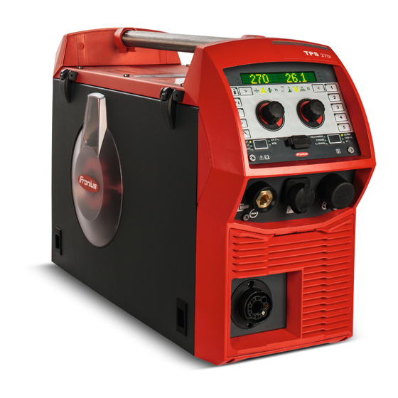
Page 21: General
General Device concept The TPS 270i C MIG/MAG power source is a completely digitised, microprocessor- controlled inverter power source with integ- rated 4-roller wire drive. The modular design and potential for sys- tem add-ons ensure a high degree of flexi- bility. -
Page 22: Warning Notices On The Device
Warning notices Warning notices and safety symbols are affixed to power sources with the CSA test mark on the device for use in North America (USA and Canada). These warning notices and safety symbols must not be removed or painted over. They warn against incorrect operation, as this may result in serious injury and damage. - Page 23 Do not use the functions described here until you have fully read and understood the fol- lowing documents: These Operating Instructions All the Operating Instructions for the system components, especially the safety rules Do not dispose of used devices with domestic waste. Dispose of them according to the safety rules.
-
Page 24: Description Of Warning Notices On The Device
Description of On certain device versions, warning notices are attached to the device. Warning Notices on the Device The arrangement of the symbols may vary. Warning! Watch Out! There are possible hazards as shown by the symbols. Drive rolls can injure fingers. Welding wire and drive parts are at welding voltage during operation Keep hands and metal objects away. - Page 25 Welding sparks can cause explosion or fire. Keep flammables away from welding. Don’t weld near flammables. Welding sparks can cause fires.Have a fire extinguisher nearby and have a watch- person ready to use it. Do not weld on drums or any closed containers. Arc rays can burn eyes and injure skin.
-
Page 26: Welding Packages, Welding Characteristics And Welding Processes
Welding packages, welding characteristics and welding processes General Various welding packages, welding characteristics and welding processes are available with TPSi power sources that enable a wide range of materials to be effectively welded. Welding charac- Depending on the welding process and shielding gas mix, various process-optimised weld- teristics ing characteristics are available when selecting the filler metal. - Page 27 galvannealed Characteristics for iron/zinc-coated sheet surfaces gap-bridging CMT, PMC Characteristics with very low heat input for optimum gap-bridging ability Hot spot Characteristics with hot start sequence, specially for plug welds and MIG/MAG spot weld joints mix ** Also required: Pulse and PMC welding packages Characteristics with process switch between pulsed and dip transfer arc Specially for welding vertical-up seams with cyclic change between a hot and cold support- ing process phase.
-
Page 28: Summary Of Mig/Mag Pulse Synergic Welding
(T.I.M.E. = Transferred Ionized Molten Energy) universal CMT, PMC, Pulse, Standard Characteristics for conventional welding tasks in renowned Fronius quality WAAM Characteristics with reduced heat input and greater stability at a higher deposition rate for welding bead onto bead in adaptive structures... -
Page 29: Summary Of Mig/Mag Standard Synergic Welding
Summary of MIG/ MIG/MAG standard synergic MAG standard synergic welding The MIG/MAG standard synergic welding process is a MIG/MAG welding process across the entire power range of the power source with the following arc types: Short circuit arc Droplet transfer takes place during a short circuit in the lower power range. Intermediate arc The droplet increases in size on the end of the wire electrode and is transferred in the mid- power range during the short circuit. -
Page 30: Summary Of The Cmt Process
Summary of the CMT = Cold Metal Transfer CMT process A special CMT drive unit is required for the CMT process. The reversing wire movement in the CMT process results in a droplet detachment with im- proved dip transfer arc properties. The advantages of the CMT process are as follows Low heat input Less spattering... -
Page 31: System Components
OPT/i TPS C polarity reverser OPT/i TPS C SpeedNet Connector Optional second SpeedNet connection socket Installed on the rear of the power source. OPT/i TPS 270i C ext. Sensor OPT/i TPS 270i C PushPull OPT/i TPS C TIG TMC OPT/i TPS 270i C Ethernet OPT/i Synergic Lines Option for enabling all special characteristics available on TPSi power sources;... - Page 32 OPT/i GUN Trigger Option for special functions in conjunction with the torch trigger...
-
Page 33: Controls, Connections And Mechanical Components
Controls, connections and mechani- cal components... -
Page 35: Control Panel
Control panel General Welding parameters can be easily changed and selected using the adjusting dial. The parameters are shown on the display while welding is in progress. The synergic function ensures that other welding parameters are also adjusted whenever an individual parameter is changed. NOTE! As a result of firmware updates, you may find that your device has certain functions that are not described in these operating instructions, or vice versa. - Page 36 Function Process control parameter indicator For the LSC and PMC welding processes Penetration stabilizer indicator Lights up if the penetration stabilizer is active Arc length stabilizer indicator Lights up when the arc length stabilizer is active Left parameter selection The corresponding indicator lights up when a parameter is selected. The following parameters can be selected by pressing the button: Material thickness * In mm or inches...
- Page 37 * Synergic parameter When a synergic parameter is changed, the synergic func- tion automatically changes all other synergic parameters to match. Display For displaying values Hold/Intermediate arc indicator Hold indicator The indicator lights up at the end of each welding operation and the actual values for the welding current, welding voltage and wire speed, etc.
- Page 38 * Synergic parameter When a synergic parameter is changed, the synergic function automatically chang- es all other synergic parameters to match. Indicators SFI indicator Lights up when SFI (Spatter Free Ignition) is active SynchroPulse indicator Lights up when SynchroPulse is active VRD indicator Lights up when the voltage reduction device (VRD) is active EasyJob buttons...
- Page 39 (12) Gas-test button For setting the required gas flow rate on the gas pressure regulator. After pressing this button, gas flows for 30 seconds. Press the button again to stop the gas flow prematurely. (13) Wire threading button To thread the wire electrode into the torch hosepack with no accompanying flow of gas or current (14) Left adjusting dial with turn/press function...
-
Page 40: Displaying Plain Text For Parameters
Displaying plain The left adjusting dial can be used to display the corresponding plain text for each param- text for parame- eter abbreviation shown on the display. ters Example: Parameter or entry from the Setup menu has been selected using the right adjusting dial;... -
Page 41: F1/F2 Special Function Parameters, Favourites Button
F1/F2 special function parameters, Favourites but- F1 and F2 special Setting F1 and F2 special function parameters function parame- I-S [%] ters ~ 3 sec. ~ 3 sec. Example: the selected parameter I-S is assigned to F1 Select the desired parameter in the Setup menu Further information on the Setup menu can be found from page To assign the selected parameter to F1 or F2, press the parameter selection button for approx. -
Page 42: The Favourites Button
Press the parameter selection button until F1 or F2 lights up: F1 ... left parameter selection F2 ... right parameter selection The stored parameter is shown first, then the currently set value of the parameter. Change the value of the parameter by turning the adjusting dial: F1 ... - Page 43 Select the desired parameter or the desired parent folder in the Setup menu Further information on the Setup menu can be found from page To assign the selected parameter or folder to the Favourites button, press the Favour- ites button for approx. 3 seconds Next to the parameter or folder and a tick are shown: The selected parameter or folder is now assigned to the Favourites button.
- Page 44 The Favourites button can also be assigned in the Setup menu (page 113).
-
Page 45: Connections, Switches And Mechanical Components
Connections, switches and mechanical components Connections, Function switches and me- chanical compo- Control panel with display nents for operating the power source (+) current socket with bayonet latch Blanking cover reserved for the TMC connection socket of the TIG option Welding torch connection for connecting the welding torch (-) current socket with bayonet... - Page 46 Function (12) Wirespool holder with brake for holding standard wirespools weighing up to 19 kg (41.89 lb.) and with a max. diameter of 300 mm (11.81 in) (13) 4 roller drive (12) (13) Side view...
-
Page 47: Installation And Commissioning
Installation and commissioning... -
Page 49: Minimum Equipment Needed For Welding Task
Minimum equipment needed for welding task General Depending on which welding process you intend to use, a certain minimum equipment lev- el will be needed in order to work with the power source. The welding processes and the minimum equipment levels required for the welding task are then described. -
Page 50: Before Installation And Commissioning
Before installation and commissioning Safety WARNING! Danger from incorrect operation. Possible serious injury and damage to property. ► Do not use the functions described here until you have read and completely under- stood these Operating Instructions. ► Do not use the functions described here until you have fully read and understood all of the Operating Instructions for the system components, in particular the safety rules! Proper use The power source may only be used for MIG/MAG, MMA and TIG welding. -
Page 51: Generator-Powered Operation
CAUTION! An inadequately dimensioned electrical installation can cause serious damage. ► The mains lead and its fuse protection must be dimensioned to suit the local power supply. The technical data shown on the rating plate applies. Generator-pow- The power source is generator-compatible. ered operation The maximum apparent power S of the power source must be known in order to select... -
Page 52: Connecting The Mains Cable
General If no mains cable is connected, a mains cable that is suitable for the connection voltage must be fitted before commissioning. Strain-relief devices for the following cable cross-sections are fitted to TPS 270i C power sources: Power source External diameter of cable... - Page 53 6 x TX25 5 x TX25 Tightening torque = 1.2 Nm IMPORTANT! When connecting the cable to the switch, ensure: To route the conductors near to the switch Not to make the conductors unnecessarily long To fit the protective hose supplied over the cable and insert the covered cable into the strain-relief device if cable diameters are small Tightening torque = 1.2 Nm Tightening torque = 1.2 Nm...
- Page 54 5 x TX25, tightening torque = 3 Nm 6 x TX25, tightening torque = 3 Nm...
-
Page 55: Start-Up
Start-up Safety WARNING! An electric shock can be fatal. If the power source is connected to the mains electricity supply during installation, there is a high risk of very serious injury and damage. ► Before carrying out any work on the device make sure that the power source mains switch is in the "O"... -
Page 56: Establishing A Ground Earth Connection
Establishing a Plug the grounding cable into the (-) ground earth con- current socket nection Lock the grounding cable in place Use the other end of the grounding ca- ble to establish a connection to the workpiece Connecting the grounding cable Connecting the Before connecting the welding torch, check that all cables, lines and hosepacks are welding torch... -
Page 57: Inserting/Replacing Feed Rollers
Inserting/replac- In order to achieve optimum wire electrode feed, the feed rollers must be suitable for the ing feed rollers diameter and alloy of the wire being welded. NOTE! Only use feed rollers that are suitable for the wire electrode. An overview of the feed rollers available and their possible areas of use can be found in the spare parts lists. -
Page 58: Inserting The Wirespool
Inserting the wire- CAUTION! spool Risk of injury due to springiness of spooled wire electrode. ► While inserting the wirespool, hold the end of the wire electrode firmly to avoid injuries caused by the wire springing back. CAUTION! Risk of injury from falling wirespool. ►... -
Page 59: Inserting The Basket-Type Spool
Inserting the bas- CAUTION! ket-type spool Risk of injury due to springiness of spooled wire electrode. ► While inserting the basket-type spool, hold the end of the wire electrode firmly to avoid injuries caused by the wire springing back. CAUTION! Risk of injury from falling basket-type spool. -
Page 60: Feeding In The Wire Electrode
Feeding in the CAUTION! wire electrode Risk of injury from springiness of spooled wire electrode. ► When inserting the wire electrode into the 4-roller drive, hold the end of the wire elec- trode firmly to avoid injuries caused by the wire springing back. CAUTION! Risk of damage to the welding torch from sharp end of wire electrode. -
Page 61: Setting The Contact Pressure
Setting the con- NOTE! tact pressure Set the contact pressure in such a way that the wire electrode is not deformed but nevertheless ensures proper wirefeed. Contact pressure U-slot rollers standard values Steel 4 - 5 CrNi 4 - 5 Tubular cored electrodes 2 -3... -
Page 62: Adjusting The Brake
Adjusting the NOTE! brake After releasing the torch trigger the wirespool should stop unreeling. Adjust brake if necessary. STOP STOP Design of the brake WARNING! Danger from incorrect installation. This can result in severe personal injury and damage to property. ►... -
Page 63: Performing R/L Alignment
Performing R/L IMPORTANT! For optimum welding results, the manufacturer recommends performing an alignment R/L alignment when starting the device for the first time and when any changes are made to the welding system. -
Page 65: Welding
Welding... -
Page 67: Mig/Mag Modes
MIG/MAG modes General WARNING! Danger from incorrect operation. Possible serious injury and damage to property. ► Do not use the functions described here until you have read and completely under- stood these Operating Instructions. ► Do not use the functions described here until you have fully read and understood all of the Operating Instructions for the system components, in particular the safety rules! See the Setup menu for information on settings, setting range and units of measurement for the available parameters. -
Page 68: 2-Step Mode
Slope 2: the welding current is steadily lowered until it reaches the final current Gas post-flow A detailed explanation of the parameters can be found in the section headed "Process pa- rameters" 2-step mode "2-step mode" is suitable for Tacking work Short weld seams Automated and robot welding 4-step mode... -
Page 69: Mig/Mag And Cmt Welding
MIG/MAG and CMT welding Safety WARNING! Danger from incorrect operation. Possible serious injury and damage to property. ► Do not use the functions described here until you have read and completely under- stood these Operating Instructions. ► Do not use the functions described here until you have fully read and understood all of the Operating Instructions for the system components, in particular the safety rules! WARNING! An electric shock can be fatal. -
Page 70: Retrieving The Currently Set Filler Metal
Retrieving the currently set filler metal Press the "Filler metal info" button The LED on the button lights up and the currently set filler metal is shown on the display: Turn the right adjusting dial The currently set wire diameter is shown on the display: Turn the right adjusting dial The currently set shielding gas is shown on the display: Turn the right adjusting dial... - Page 71 Press the right adjusting dial The first available filler metal is displayed: Select the desired filler metal by turning the right adjusting dial Press the right adjusting dial "diameter?" is shown on the display: * Press the right adjusting dial The first available wire diameter is displayed: Select the desired wire diameter by turning the right adjusting dial Press the right adjusting dial...
-
Page 72: Setting The Welding Parameters
22.8 5O.O Setting the weld- ing parameters Press the button until the desired welding parameter lights up Material thickness Welding current Wire speed Special function Turn the left adjusting dial to change the value of the welding parameter If necessary: press the button until the desired welding parameter lights up Arc length correction Welding voltage... -
Page 73: Setting The Shielding Gas Flow Rate
Setting the Open the gas cylinder valve shielding gas Press the gas test button flow rate Shielding gas flows out Turn the adjusting screw on the underside of the pressure regulator until the pressure gauge shows the required shielding gas flow rate Press the gas test button The flow of gas stops. -
Page 74: Mig/Mag And Cmt Welding Parameters
MIG/MAG and CMT welding parameters Welding parame- The following welding parameters can be set and displayed for MIG/MAG pulse synergic ters for MIG/MAG welding, CMT welding and PMC welding: pulse synergic welding, for CMT using the left adjusting dial: welding and PMC welding Material thickness Setting range: 0.1 - 30.0 mm... -
Page 75: Welding Parameters For Mig/Mag Standard Synergic Welding And Lsc Welding
using the right adjusting dial: Arc length correction for correcting the arc length; Setting range: -10 - +10 Factory setting: 0 - ..shorter arc length 0 ... neutral arc length + ... longer arc length Welding voltage in V Setting range: depends on the welding process and welding program selected Before the start of welding, the machine automatically displays a standard value based on the programmed parameters. - Page 76 Welding current in A Setting range: depends on the welding process and welding program selected Before the start of welding, the machine automatically displays a standard value based on the programmed parameters. The actual value is displayed during welding. Wire speed for setting a harder, more stable arc Setting range: 0.5 - 25 m/min / 20 - 980 ipm.
-
Page 77: Welding Parameters For Mig/Mag Standard Manual Welding
Welding voltage in V Setting range: depends on the welding process and welding program selected Before the start of welding, the machine automatically displays a standard value based on the programmed parameters. The actual value is displayed during welding. Pulse/dynamic correction for influencing the short-circuiting dynamic at the instant of droplet transfer Setting range: -10 - +10 Factory setting: 0... -
Page 78: Explanation Of Footnotes
using the right adjusting dial: Welding voltage in V Setting range: depends on the welding process and welding program selected Pulse/dynamic correction for influencing the short-circuiting dynamic at the instant of droplet transfer Setting range: 0 - 10 Factory setting: 0 0 ... -
Page 79: Easyjob Mode
EasyJob mode General The 5 EasyJob buttons enable up to 5 operating points to be saved quickly. The current welding settings are saved. EasyJob mode ~ 3 sec. < 3 sec. > 5 sec. Storing EasyJob operating points To store the current welding settings, press one of the EasyJob buttons for approx. 3 seconds. - Page 80 After a total of approx. 5 seconds the EasyJob button LED goes out and "Job", the but- ton number and an X are shown on the display, e.g.: The EasyJob operating point has been deleted.
-
Page 81: Spot Welding
Spot welding Spot welding Spot welding can be carried out in the following welding processes: PULSE SYNERGIC | SYNERGIC | MANUAL | LSC/PMC | SP (CMT) Select the desired welding process by pressing the "Welding process" button Select the MODE by pressing the "Mode" button "Spot"... - Page 82 Lift the torch off the workpiece NOTE! Pre-set start of welding and end of welding parameters are also active for spot weld- ing. ► A start of welding / end of welding action for spot welding can be stored in the Setup menu under Process parameters / Start/End.
-
Page 83: Tig Welding
TIG welding Safety WARNING! Danger from incorrect operation. Possible serious injury and damage to property. ► Do not use the functions described here until you have read and completely under- stood these Operating Instructions. ► Do not use the functions described here until you have fully read and understood all of the Operating Instructions for the system components, in particular the safety rules! WARNING! An electric shock can be fatal. - Page 84 Press the "Welding process" button until the LED for the STICK/TIG welding process lights up and "TIG" is shown on the display. After a short time, the currently set welding current is shown on the display. The welding current indicator lights up. The welding voltage is applied to the welding socket with a three second time lag.
-
Page 85: Igniting The Arc
Igniting the arc The welding arc is ignited by touching the workpiece with the tungsten electrode. Place the gas nozzle on the ignition location so that there is a gap of 2-3 mm (0.08 - 0.12 in.) between the tip of the tungsten electrode and the workpiece Gradually tilt the welding torch up until the tungsten electrode touches the workpiece Raise the torch and tilt it into the normal position - the arc now ignites Carry out welding... -
Page 86: Mma Welding
MMA welding Safety WARNING! Danger from incorrect operation. Possible serious injury and damage to property. ► Do not use the functions described here until you have read and completely under- stood these Operating Instructions. ► Do not use the functions described here until you have fully read and understood all of the Operating Instructions for the system components, in particular the safety rules! WARNING! An electric shock can be fatal. - Page 87 IMPORTANT! For optimum welding results, the manufacturer recommends performing an R/L alignment when starting the device for the first time and when any changes are made to the welding system. STICK Press the "Welding process" button until the LED for the STICK/TIG welding process lights up and "STICK"...
-
Page 88: Welding Parameters For Manual Metal Arc Welding
Welding parame- The following welding parameters can be set and displayed for manual metal arc welding: ters for manual metal arc welding using the left adjusting dial: Main current in A Setting range: depends on the power source available Before the start of welding, the machine automatically displays a standard value based on the programmed parameters. -
Page 89: Setup Settings
Setup settings... -
Page 91: Setup Menu - Overview
Setup menu - overview Entering/exiting the Setup menu To enter the Setup menu, press the "Welding process" and "Mode" buttons at the same time "Process parameters" is shown on the display. To exit the Setup menu, press the "Welding process" and "Mode" buttons at the same time... -
Page 92: Setup Menu - Overview
Setup menu - overview Process param. Settings Language xx Start/End Display System back Gas-setup Process c. Spot welding Components Unit CLS [s] STICK Standard UIBS Web-PWreset SynchroPulse DRSL. Information Process Mix F1/F2 Param iJob xx R/L-check/alignm. Favourite < back System data <... -
Page 93: Process Parameters
Process parameters Process parame- The following process parameters can be set and displayed for the start and end of weld- ters for start of ing: welding/end of welding Starting current For setting the starting current for MIG/MAG welding (e.g. aluminium welding start-up) Setting range: 0 - 200% (of welding current) Factory setting: 135% Start arc length correction... - Page 94 End arc length correction For correcting the arc length at the end of welding Setting range: -10 - +10% (of welding voltage) Factory setting: 0 - ..shorter arc length 0 ... neutral arc length + ... longer arc length Final current time For setting the length of time for which the final current is to be active Setting range: off / 0.1 - 10.0 s...
-
Page 95: Process Parameters For Gas-Setup
Process parame- The following process parameters can be set and displayed for Gas-Setup: ters for Gas-Set- Gas pre-flow For setting the gas flow time before the arc is ignited Setting range: 0 - 9.9 s Factory setting: 0.1 s Gas post-flow For setting the gas flow time after the arc has gone out Setting range: 0 - 9.9 s Factory setting: 0.5 s... - Page 96 Application examples Penetration stabilizer = 0 m/min (not activated) I [A] [m/min] t [s] < s > x Penetration stabilizer = 0 m/min (not activated) Changing the contact tube distance (h) alters the resistance in the welding circuit due to the longer stick out (s The constant voltage control for constant arc length causes a reduction in the mean current value and hence a smaller penetration (x...
-
Page 97: Arc Length Stabilizer
I [A] [m/min] 0,5 m/min t [s] < s > x Penetration stabilizer = 0.5 m/min (activated) To minimise the change in welding current if the stick out is changed (s ==> s ), the wire speed is increased or reduced by 0.5 m/min. In the example shown, the stabilising effect is obtained without a change in current up to the set value of 0.5 m/min (Position 2). - Page 98 I [A] [m/min] U [V] t [s] > L > L Arc length stabilizer = 0 / 0.5 / 2.0 Activating the arc length stabilizer reduces the arc length until short circuits start to occur. The frequency of the short circuits is controlled and kept stable. Increasing the arc length stabilizer causes a further shortening of the arc length (L1 ==>...
-
Page 99: Combination Of Penetration Stabilizer And Arc Length Stabilizer
Combination of Example: Stick out change penetration stabi- lizer and arc Arc length stabilizer without penetration stabilizer length stabilizer The advantages of a short arc are main- tained even if the stick out is changed, sin- ce the short-circuit properties stay the same. -
Page 100: Process Parameters For Spot Welding
Process parame- ters for spot weld- Spot welding time 0.1 - 10.0 s Factory setting: 1.0 s Process parame- The following process parameters can be set and displayed for the system components of ters for monitor- a welding system: ing and components Cooling unit mode To determine whether a cooling unit is to be switched on or off, or operated automatically... -
Page 101: Process Parameters For Electrode Setup
(only in conjunction with the OPT/i gas controller option) Setting range: auto, 0.90 - 20.0 Factory setting: auto (the correction factor is automatically set for standard gases from the Fronius welding da- tabase) Process parame- The following process parameters can be set and displayed for manual metal arc welding... - Page 102 Example of pre-set arc-force dynamic where characteristic (4) is selected Example of pre-set arc-force dynamic where characteristic (5) or (6) is selected I-constant (constant welding current) If the "I-constant" parameter is set, the welding current will be kept constant, irrespec- tive of the welding voltage.
-
Page 103: Process Parameters For Tig Setup
If the arc length changes (e.g. in accordance with the load line (2)) the resulting operating point will be the point where the corresponding characteristic (4), (5) or (6) intersects with the load line (2). Applies to characteristics (5) and (6): Depending upon the welding voltage (arc length), the welding current (I) will also become either smaller or larger, even though the value set for remains the same. - Page 104 Sequence: Welding At the end of the welding action, briefly raise the welding torch The arc length is increased significantly. Lower the welding torch The arc length is reduced significantly The TIG Comfort Stop function is triggered Keep the welding torch at the same height The welding current is continuously decreased (downslope).
-
Page 105: Process Parameters For Synchropulse
Process parame- The following process parameters can be set for SynchroPulse welding: ters for Synchro- Syn-Puls Pulse SynchroPulse To activate/deactivate SynchroPulse Setting range: off / on Factory setting: off Wire speed For setting the average wire speed and therefore the welding power for SynchroPulse Setting range: 1.0 - 25.0 m/min (40 - 985 ipm) Factory setting: 5 m/min Delta wire feed... - Page 106 Al-l Arc correction low For correcting the arc length for SynchroPulse in the lower operating point (= average wire speed less Delta wire feed) Setting range: -10.0 - +10.0 Factory setting: 0 - ..short arc 0 ... uncorrected arc length + ...
-
Page 107: Process Parameters For Process Mix
Process parame- The following process parameters for mixed processes can be set under "Process mix": ters for Process PMC mix I [A] [m/min] t [ms] Mixed process between PMC and LSC welding process. A cold LSC process phase follows a hot PMC process phase as part of a cycle. - Page 108 Wire speed Is taken from the welding parameters Setting range: 1.0 - 25.0 m/min (40 - 985 ipm) The wire speed value can also be specified or changed in the Process mix parameters. Arc length correction Is taken from the welding parameters Setting range: -10.0 - +10.0 The arc length correction value can also be specified or changed in the Process mix pa- rameters.
-
Page 109: R/L Alignment
If the lower power time correction is increased, the process frequency reduces and the LSC process phase becomes longer. If the lower power time correction is reduced, the process frequency increases and the LSC process phase becomes shorter. Lower power correction To set the energy input in the cold process phase in a mixed process Setting range: -10.0 - +10.0 Factory setting: 0... - Page 110 After a successful measurement, the current values are displayed. Select "Finish" by turning the right adjusting dial Press the right adjusting dial To exit the Setup menu, press the "Welding process" and "Mode" buttons at the same time...
-
Page 111: Settings
Settings General remarks NOTE! As a result of firmware updates, you may find that there are functions available on your unit that are not described in these operating instructions or vice versa. Certain illustrations may also differ slightly from the actual control elements on your device. However, these controls function in exactly the same way. -
Page 112: Setting The Standards
Setting the stand- Select Setup menu / Settings / View / Standard ards Press the right adjusting dial The first of the available standards is displayed. Select the desired standard by turning the right adjusting dial: Name of filler metal according to European standards (e.g. -
Page 113: Setting The Favourites Button Via The Setup Menu
Turn the right adjusting dial to determine under which special function the parameter should be stored: - ... the parameter is not assigned to a special function/a stored parameter is deleted F1 ... parameter is stored under special function F1 F2 ... -
Page 114: Setting The Interior Lighting
Current arc energy in kJ The arc energy is the sum total of the arc power and calculates the heat input of the weld seam most recently produced. If the weld seam length is known the electrical energy input can be calculated: E = IE / L Electrical energy input in kJ/cm Arc energy in kJ... -
Page 115: Restoring The Factory Settings
Restoring the fac- Select Setup menu / Settings / System / FAC tory settings Press the right adjusting dial Turn the right adjusting dial to select "Yes", thereby restoring the power source to the factory settings Press the right adjusting dial The process parameters and machine default values are immediately reset to the factory settings without any further warning. -
Page 116: Setting The Mode For Spot Welding
The following can now be set and carried out on the JobMaster welding torch: Mode SynchroPulse Gas test Setting the mode Select Setup menu / Settings / System / SPm for spot welding Press the adjusting dial Turn the adjusting dial and select the desired mode for spot welding 2-step = spot welding in 2-step mode: The spot welding process runs for as long as the torch trigger is kept pressed and ends no later than at the expiry of the spot welding time. -
Page 117: Setting The Language
Setting the language Setting the lan- Access the Setup menu guage Select the language Press the right adjusting dial The language abbreviation of the currently set language is highlighted on the display. Select the desired language by turning the right adjusting dial The following languages can be selected: Czech Dutch... -
Page 118: Keylock
Keylock Keylock To activate the keylock Press the "Welding process" and left parameter selection buttons at the same time Alternatively, the "Mode" and right parameter selection buttons can be pressed. The key symbol and a tick are shown on the display: The following functions are disabled: The following functions are available: the adjusting dial functions... -
Page 119: Smartmanager - The Power Source Website
SmartManager - The power source website... -
Page 121: Smartmanager - The Power Source Website
SmartManager - The power source website General remarks The power source has its own website: SmartManager. As soon as the power source is connected to a computer with the help of a network cable, or is integrated into a network, the power source's SmartManager can be retrieved using the power source's IP address. -
Page 122: Settings
The languages available for SmartManager can be displayed by clicking on tion the language abbreviation. The language that is currently set is highlighted in white. To change the language, click on the one you would like. Fronius A click on the Fronius logo opens the homepage of Fronius: www.fronius.com. -
Page 123: Overview
Overview Overview In the overview entry, welding system components and options are displayed with all avail- able information, e.g. firmware version, item number, serial number, production date, etc. Expand all Click the "Expand all groups" button to show more details of the individual system compo- groups / Reduce nents. -
Page 124: Update
To restart the power source, click on "Yes" The power source restarts; the display goes black for a short time. The Fronius logo is shown on the power source display during the restart. Once the update has been completed successfully, confirmation and the current firm- ware version are displayed. -
Page 125: Fronius Weldconnect
Fronius Weld- The mobile application Fronius WeldConnect can also be called up in the "Update" entry. Connect Fronius WeldConnect helps welders, design engineers and work schedulers to estimate various welding parameters. Fronius WeldConnect Fronius WeldConnect is available in the following forms:... -
Page 126: Screenshot
Screenshot Screenshot In the Screenshot entry, a digital image of the power source display can be created at any time, irrespective of the navigation or set values. Click on "Create screenshot" to capture a screenshot of the display A screenshot of the currently displayed settings is created. Different functions are available for saving the screenshot depending on the browser used;... -
Page 127: Backup & Restore
Backup & Restore General remarks In the backup & restore entry all welding system data can be saved as a backup (e.g. current parameter settings, jobs, user characteristics, defaults, etc.), any backups will be restored to the welding system You can select which data you would like to be backed up automatically. Backup &... -
Page 128: Automatic Backup
Automatic back- Enter data for automatic backup Interval settings Interval: daily / weekly / monthly at: Time (hh:mm) Backup target Protocol: SFTB / SMB Server, port, storage location, domain/user, password Proxy settings Server, port, user, password Save changes Trigger automatic backup... -
Page 129: Function Packages
Function Packages Function Packag- In the Function Packages entry, the function packages, special characteristics, options, etc., present on the power source are displayed. New function packages can also be uploaded. Welding Packag- Under Welding Packages, the welding packages present on the power source are dis- played with their respective item numbers, e.g.: WP Standard, (MIG/MAG standard synergic welding) WP Pulse (MIG/MAG pulse synergic welding) -
Page 130: Synergic Lines Overview
Synergic lines overview Characteristics In the Characteristics overview entry: overview Available characteristics in the welding system can be displayed: (Available characteristics button). Possible characteristics in the welding system can be displayed: (Possible characteristics button). You can search for, sort and filter the displayed characteristics at any time. The following information is displayed for the characteristics: Status Replaced by... -
Page 131: Troubleshooting And Maintenance
Troubleshooting and maintenance... -
Page 133: The Error Menu
The Error menu The Error menu Notifications, warnings and errors are shown on the display with the corresponding num- ber. If an error occurs, the Error menu is always in the foreground. Pressing the right adjusting dial opens the Error menu on "confirm". Pressing the right adjusting dial a second time confirms the error;... -
Page 134: Troubleshooting
Troubleshooting General The power sources are equipped with an intelligent safety system, meaning it has been possible to dispense with nearly all fuses. After a possible malfunction has been remedied, the power source can be used again as normal. Possible malfunctions, warning notices or status codes are shown on the display as plain text dialogues. - Page 135 No welding current Mains switch is on, overtemperature is displayed Cause: Overload; the duty cycle has been exceeded Remedy: Check duty cycle Cause: Thermostatic automatic circuit breaker has been tripped Remedy: Wait until the power source automatically comes back on after the end of the cooling phase Cause: Limited supply of cooling air...
- Page 136 Poor weld properties Cause: Incorrect welding parameters Remedy: Check the settings Cause: Poor ground earth connection Remedy: Ensure good contact to workpiece Cause: Inadequate or no protective gas shield Remedy: Check the pressure regulator, gas hose, gas solenoid valve, torch gas con- nection, etc.
- Page 137 Welding torch becomes very hot Cause: The specification of the welding torch is inadequate Remedy: Observe the duty cycle and loading limits Cause: Only on water-cooled systems: Inadequate coolant flow Remedy: Check coolant level, coolant flow, for coolant contamination, etc. For further information refer to the cooling unit operating instructions.
-
Page 138: Care, Maintenance And Disposal
Care, maintenance and disposal General Under normal operating conditions, the power source requires only a minimum of care and maintenance. However, it is vital to observe some important points to ensure the welding system remains in a usable condition for many years. Safety WARNING! An electric shock can be fatal. -
Page 139: Disposal
Get latest firmware (e.g. from the Fronius Download Center) File format: official_tpsi_x.x.x-xxxx.ffw Establish Ethernet connection between PC/laptop and power source Open the power source SmartManager (see page External Link: “”) Transfer the firmware to the power source (see page External Link: “”) -
Page 141: Technical Data
Technical data... -
Page 143: Technical Data
Technical data Explanation of Duty cycle (D.C.) is the proportion of time in a 10-minute cycle at which the device may be the term "duty cy- operated at its rated output without overheating. cle" NOTE! The D. C. values specified on the rating plate are based on an ambient temperature of 40°C. If the ambient temperature is higher, either the D.C. -
Page 144: Tps 270I C
0.03 - 0.06 in. Wirespool diameter max. 300 mm max. 11.8 in. Wirespool weight max. 19.0 kg max. 41.9 lb. The wirefeeder for the TPS 270i C is integrated in the power source. Interface to a 230/400 V, 50 Hz public grid... -
Page 145: Tps 270I C /Nc
TPS 270i C /nc Mains voltage (U 3 x 380 / 400 / 460 V Max. effective primary current (I 1eff 3 x 380 V 9.5 A 3 x 400 V 9.7 A 3 x 460 V 8.5 A Max. primary current (I... -
Page 146: Tps 270I C /Mv/Nc
11.8 in. Wirespool weight max. 19.0 kg max. 41.9 lb. The wirefeeder for the TPS 270i C is integrated in the power source. Interface to a 230/400 V, 50 Hz public grid TPS 270i C /MV/nc Mains voltage (U 3 x 200 / 230 / 380 / 400 / 460 V Max. - Page 147 0.03 - 0.06 in. Wirespool diameter max. 300 mm max. 11.8 in. Wirespool weight max. 19.0 kg max. 41.9 lb. The wirefeeder for the TPS 270i C is integrated in the power source. Interface to a 230/400 V, 50 Hz public grid...
-
Page 148: Tps 270I C /S/Nc
Wire diameter 0.8 - 1.6 mm 0.03 - 0.06 in. Wirespool diameter max. 300 mm max. 11.8 in. Wirespool weight max. 19.0 kg / max. 41.9 lb. The wirefeeder for the TPS 270i C is integrated in the power source. - Page 152 FRONIUS INTERNATIONAL GMBH Froniusstraße 1, A-4643 Pettenbach, Austria E-Mail: sales@fronius.com www.fronius.com Under www.fronius.com/contact you will find the addresses of all Fronius Sales & Service Partners and locations...
Need help?
Do you have a question about the TPS 270i C and is the answer not in the manual?
Questions and answers