
Related Manuals for Fronius TPS/i Robotics PushPull CMT


Summary of Contents for Fronius TPS/i Robotics PushPull CMT
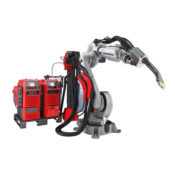
- Page 1 / Perfect Charging / Perfect Welding / Solar Energy Operating Instructions TPS/i Robotics Pull welding system TPS/i Robotics PushPull CMT welding system 42,0426,0219,EN 009-13072018...
- Page 3 Thank you for the trust you have placed in our company and congratulations on buying this high-quality Fronius product. These instructions will help you familiarise yourself with the product. Reading the instructions carefully will enable you to learn about the many different features it has to offer.
-
Page 5: Table Of Contents
Contents Safety rules ..............................General ..............................Proper use ............................Environmental conditions........................Obligations of the operator........................Obligations of personnel ........................Mains connection ..........................Protecting yourself and others ......................Danger from toxic gases and vapours ....................Danger from flying sparks ........................Risks from mains current and welding current..................Meandering welding currents........................ - Page 6 WF Robacta Drive............................General ..............................Warning notices on the device......................CrashBox /i ..............................General ..............................Also required for fitting to robot arm...................... Device concept ............................. Areas of utilisation..........................Scope of supply ............................ Robot welding torch ........................... Safety..............................General ..............................TPSi wire buffer ............................General ..............................
- Page 7 Safety..............................General ..............................Connecting the SplitBox to the system components................Fitting the inner liner (unreeling wirefeeder - SplitBox SB 500i R)............Fitting the inner liner (SplitBox - WF 25i with internal inner liner) ............Fitting the inner liner (unreeling wirefeeder- WF Robacta Drive with external wirefeeding hose) ..Fitting the inner liner (wire buffer - WF Robacta Drive with external wirefeeding hose) .......
- Page 8 Troubleshooting, maintenance and disposal Troubleshooting ............................119 Safety..............................119 Fault diagnosis............................119 Care, maintenance and disposal ....................... 123 General ..............................123 Safety..............................123 Every start-up............................123 Whenever the welding torch or torch hosepack is changed ..............123 Changing the torch hosepack, changing the interconnecting hosepack..........124 Every 6 months .............................
-
Page 9: Safety Rules
Safety rules General The device is manufactured using state-of-the-art technology and according to recognised safety standards. If used incorrectly or misused, however, it can cause: injury or death to the operator or a third party, damage to the device and other material assets belonging to the operat- ing company, inefficient operation of the device. -
Page 10: Environmental Conditions
Environmental Operation or storage of the device outside the stipulated area will be deemed as not in ac- conditions cordance with the intended purpose. The manufacturer shall not be held liable for any dam- age arising from such usage. Ambient temperature range: during operation: -10 °C to + 40 °C (14 °F to 104 °F) during transport and storage: -20 °C to +55 °C (-4 °F to 131 °F) Relative humidity:... -
Page 11: Protecting Yourself And Others
Protecting your- Anyone working with the device exposes themselves to numerous risks, e.g. self and others flying sparks and hot pieces of metal Arc radiation, which can damage eyes and skin Hazardous electromagnetic fields, which can endanger the lives of those using cardi- ac pacemakers Risk of electrocution from mains current and welding current Greater noise pollution... -
Page 12: Danger From Flying Sparks
Danger from fly- Flying sparks may cause fires or explosions. ing sparks Never weld close to flammable materials. Flammable materials must be at least 11 metres (36 ft. 1.07 in.) away from the arc, or al- ternatively covered with an approved cover. A suitable, tested fire extinguisher must be available and ready for use. -
Page 13: Meandering Welding Currents
After opening the device: Discharge all live components Ensure that all components in the device are de-energised If work on live parts is required, appoint a second person to switch off the main switch at the right moment. Meandering weld- If the following instructions are ignored, meandering welding currents can develop with the ing currents following consequences:... -
Page 14: Emf Measures
Supporting measures for avoidance of EMC problems: Mains supply If electromagnetic interference arises despite correct mains connection, addition- al measures are necessary (e.g. use a suitable line filter). Welding power leads must be kept as short as possible must run close together (to avoid EMF problems) must be kept well apart from other leads Equipotential bonding Earthing of the workpiece... -
Page 15: Factors Affecting Welding Results
Risk of scalding from escaping coolant. Switch off cooling unit before disconnecting cool- ant flow or return lines. Observe the information on the coolant safety data sheet when handling coolant. The cool- ant safety data sheet may be obtained from your service centre or downloaded from the manufacturer's website. -
Page 16: Danger From Escaping Shielding Gas
Close the shielding gas cylinder valve if no welding is taking place. If the shielding gas cylinder is not connected, leave the valve cap in place on the cylinder. The manufacturer's instructions must be observed as well as applicable national and inter- national regulations for shielding gas cylinders and accessories. -
Page 17: Commissioning, Maintenance And Repair
Check the device at least once a week for obvious damage and proper functioning of safety devices. Always fasten the shielding gas cylinder securely and remove it beforehand if the device is to be transported by crane. Only the manufacturer's original coolant is suitable for use with our devices due to its prop- erties (electrical conductibility, anti-freeze agent, material compatibility, flammability, etc.). -
Page 18: Disposal
(e.g. relevant product standards of the EN 60 974 se- ries). Fronius International GmbH hereby declares that the device is compliant with Directive 2014/53/EU. The full text on the EU Declaration of Conformity can be found at the following address: http://www.fronius.com... -
Page 19: General Information
General information... -
Page 21: General
General Overview of the The conventional TPS/i welding system with internal wirefeeding hose is available in two conventional TPS different variants: /i welding system Variant A: with an unreeling wirefeeder (4) with internal wire- Variant B: with an unreeling wirefeeder (2) feeding hose Variant C: with two unreeling wirefeeders (2) and (4) The variants differ in terms of the possible wirefeeding distance. -
Page 22: Overview Of The Conventional Tps /I Welding System With External Wirefeeding Hose
Overview of the The conventional TPS/i welding system with external wirefeeding hose is available in three conventional TPS different variants: /i welding system Variant A: without an unreeling wirefeeder with external Variant B: with an unreeling wirefeeder (2) wirefeeding hose Variant C: with two unreeling wirefeeders (2) and (5) The variants differ in terms of the possible wirefeeding distance. -
Page 23: Overview Of The Tps/I Pap Welding System
Overview of the The TPS/i PAP welding system is available in three different variants: TPS/i PAP weld- Variant A: with PowerLiner (3) ing system Variant B: with an unreeling wirefeeder (2) Variant C: with two unreeling wirefeeders (2) and (5) The variants differ in terms of the possible wirefeeding distance. -
Page 24: Overview Of The Conventional Tps /I Cmt Welding System
Overview of the conventional TPS /i CMT welding system max. 4 m max. 6 m 0 - max. 8 m (10) (14) (15) (11) (13) (12) Wire drum Unreeling wirefeeder, for example WF 30i REEL 2R Wirefeeding hose or PowerLiner Interconnecting hosepack Media splitter, for example SB 500i R "QuickConnect"... -
Page 25: Overview Of The Tps /I Pap Cmt Welding System
Overview of the TPS /i PAP CMT welding system max. 6 m max. (14) (15) 0 - max. 8 m (10) (11) (13) (12) Wire drum Unreeling wirefeeder, for example WF 30i REEL 2R Wirefeeding hose Interconnecting hosepack Media splitter, for example SB 500i R "QuickConnect"... -
Page 26: Interconnecting Hosepack
Interconnecting hosepack General remarks The interconnecting hosepack connects the power source to the wirefeeder. With the TPS/ i welding system the interconnecting hosepack is available in two versions - one split and one continuous variant. 3 / 5 / 10 / 15 m (extension - split variant) 4 / 8 m (connection - continuous variant) General The interconnecting hosepack connects the power source to the SplitBox SB 60i R. -
Page 27: Powerliner
PowerLiner General The PowerLiner is a wirefeeder system for all standard wire types. Wire diameters of 0.6 mm to 1.6 mm may be used. The PowerLiner does not need an inner liner. The wire electrode is guided by rollers set at an angle of 90 degrees. -
Page 28: Wf 25I Reel R /4R, Wf 30I Reel R /2R
Proper use The device is designed exclusively for wirefeeding in automated MIG/MAG welding appli- cations in conjunction with Fronius system components. Any use above and beyond this purpose is deemed improper. The manufacturer shall not be held liable for any damage arising from such usage. -
Page 29: Warning Notices On The Device
Warning notices The device is fitted with safety symbols and a rating plate. The safety symbols and rating on the device plate must not be removed or painted over. The safety symbols warn against operating the equipment incorrectly, as this may result in serious injury and damage. 40,0006,3035 e.g.: WF 30i REEL R /2R/G/W Do not dispose of used devices with domestic waste. - Page 30 Keep hands, hair, clothing and tools away from moving parts. For example: Cogs Feed rollers Wirespools and welding wires Do not reach into the rotating cogs of the wire drive or into rotating drive com- ponents. Covers and side panels may only be opened/removed while maintenance or re- pair work is being carried out.
-
Page 31: Splitbox Sb 500I R
Proper use The device is designed exclusively for bringing together the welding media in automated MIG/MAG welding applications in conjunction with Fronius system components. Any use above and beyond this purpose is deemed improper. The manufacturer shall not be held liable for any damage arising from such usage. -
Page 32: Warning Notices On The Device
The safety symbols warn against operating the equipment incorrectly, as this may result in serious injury and damage. SB 500i R /G/W/FSC 4,040,080 Part No.: www.fronius.com XXXXXXXXXX Ser.No.: IEC 60 974-1/-10 Cl.A IP 43 60 V 0.8 A... -
Page 33: Splitbox Sb 60I R
Proper use The device is designed exclusively for bringing together the welding media in automated MIG/MAG welding applications in conjunction with Fronius system components. Any use above and beyond this purpose is deemed improper. The manufacturer shall not be held liable for any damage arising from such usage. -
Page 34: Warning Notices On The Device
Warning notices The device is fitted with safety symbols and a rating plate. The safety symbols and rating on the device plate must not be removed or painted over. The safety symbols warn against operating the equipment incorrectly, as this may result in serious injury and damage. Welding is dangerous. -
Page 35: Pushpull Hosepack
PushPull hosepack General The Robacta MHPi RD hosepack is designed for gas-cooled and water-cooled robot appli- cations. It connects the SplitBox to the wirefeeder. The length of the hosepack depends on the robot. The following combinations are available: Robacta MHPi RD conventional SB500i ->... -
Page 36: Wf Robacta Drive
WF Robacta Drive General The WF 25i Robacta Drive and WF 60i Ro- bacta Drive CMT are designed for gas or water-cooled systems. The built-in motor ensures precise wirefeeding (pull system). The torch body is fitted to the Robacta Dri- Warning notices The device is fitted with safety symbols and a rating plate. -
Page 37: Crashbox /I
CrashBox /i General A CrashBox Drive /i PAP mounted onto the robot arm A CrashBox Drive /i mounted onto the robot arm with with Robacta Drive and MTB clamp system, Robacta Drive und MTB The CrashBox Drive /i is a protection device for the torch body, the drive unit and the torch interchangeable-coupling. -
Page 38: Areas Of Utilisation
Areas of utilisa- The clamp system can be used for the following PushPull robot hosepacks: tion MHP /i G/W RD hosepacks Scope of supply (3) (2) CrashBox Drive /i PAP scope of supply Conventional CrashBox /i scope of supply CrashBox Drive /i holder Locking ring fitted to (3) on delivery Bellows Magnetic ring with three M4x16 cheesehead screws... -
Page 39: Robot Welding Torch
Robot welding torch Safety CAUTION! Risk of burns from hot torch neck, hot torch neck coupling and other hot welding torch components. Before starting work on the torch neck, the torch neck coupling and all other welding torch components: allow the torch neck, torch neck coupling and all other welding torch compo- nents to cool down to room temperature (+25 °C, +77 °F) wear electrically insulated and heat protective gloves use a suitable tool... -
Page 40: Tpsi Wire Buffer
TPSi wire buffer General As its name implies, the wire buffer acts as a buffer for the rapid reversing movements of the wire electrode needed during the CMT welding process. The wire buffer can also be used to help coordinate two drive systems that work in different ways. -
Page 41: Controls, Connections And Mechanical Components
Controls, connections and mechani- cal components... -
Page 43: Splitbox
SplitBox Safety WARNING! Operating the equipment incorrectly can cause serious injury and damage. All the functions described may only be used by trained and qualified personnel. Do not use the functions described until you have thoroughly read and understood the following documents: this document all the operating instructions for the system components, especially the safe- ty rules... - Page 44 Function NOTE! If there was a ground earth connection with the contact tip before the wire retract button was pressed, the wire electrode will be retracted when the button is pressed until it is short-circuit-free – it retracts by no more than 10 mm (0.39 in.) with each press of the button.
-
Page 45: Control Elements, Connections And Mechanical Components Of The Splitbox
Control elements, connections and mechanical components of the SplitBox Safety WARNING! Operating the equipment incorrectly can cause serious injury and damage. All the functions described may only be used by trained and qualified personnel. Do not use the functions described until you have thoroughly read and understood the following documents: this document all the operating instructions for the system components, especially the safe-... -
Page 46: Sb 60I R:control Elements, Connections And Mechanical Components
Welding torch connection SpeedNet connection socket for connecting the SpeedNet cable from the interconnecting hosepack Blanking cover for option 5 Shielding gas connection (+) current socket for connecting the power cable from the interconnecting hosepack Blanking cover for option 2 (10) Wire infeed Function... -
Page 47: Sb 60I R /L:control Elements, Connections And Mechanical Components
Function Welding torch connection Coolant hoses to welding torch Blanking cover (SpeedNet or exter- nal sensor option) A - Welding torch end Function Wire infeed (via QuickConnect and inner liner) 16 bar gas purging (option) (10) Hosepack (fixed) preconfigured for gas / water- cooled applications 3 / 4 / 8 m B - Power source end... - Page 48 Function Welding torch connection Coolant hoses to welding torch Blanking cover (SpeedNet or exter- nal sensor option) A - Welding torch end Function Wire infeed (via QuickConnect and inner liner) 16 bar gas purging (option) (10) Hosepack (fixed) preconfigured for gas / water- cooled applications 3 / 4 / 8 m B - Power source end...
-
Page 49: Sb 500I R Pap Control Elements, Connections And Mechanical Components
SB 500i R PAP control elements, connections and mechanical components Safety WARNING! Operating the equipment incorrectly can cause serious injury and damage. All the functions described may only be used by trained and qualified personnel. Do not use the functions described until you have thoroughly read and understood the following documents: this document all the operating instructions for the system components, especially the safe-... - Page 50 Function (11) Cover (12) Implementation (13) Gas test / wire threading control panel (option) Side view...
-
Page 51: Wf 25I Robacta Drive Control Panel / Wf 60I Robacta Drive Cmt
WF 25i Robacta Drive control panel / WF 60i Robacta Drive CMT WF 25i Robacta Function Drive control pan- Gas-test button el / WF 60i Robac- for setting the required gas flow ta Drive CMT rate on the pressure regulator Gas will flow out for 30 sec- onds after the gas-test but- ton is pressed. - Page 52 Function Wire threading button For threading the wire electrode into the torch hosepack with no accompanying flow of gas or current While the button is being pressed, the wirefeeder runs at the preset wire re- tract speed Wire threading can be performed using one of two methods: Method 1 Threading the wire electrode using the preset feeder inching speed: Press and hold the wire threading button...
-
Page 53: Wf 25I Reel R /4R, Wf 30I Reel R /2R
WF 25i REEL R /4R, WF 30i REEL R /2R Safety WARNING! Operating the equipment incorrectly can cause serious injury and damage. All the functions described may only be used by trained and qualified personnel. Do not use the functions described until you have thoroughly read and understood the following documents: this document all the operating instructions for the system components, especially the safe-... - Page 54 100 mm 3.9 in. 4 x M5 (13) (12) Top/underside Function Cover Protective cover for the 4-roller drive 4-roller drive Protective cover for the 2-roller drive 2-roller drive Opening for optional sash lock Control panel SpeedNet connection Blanking cover for optional component (10) Blanking cover for optional component (11)
-
Page 55: Control Panel
Control panel Function Operating status LED lights green when the device is ready for use Gas-test button for setting the required gas flow rate on the pressure regulator Gas will flow out for 30 s after pressing the gas-test button. Press the button again to stop the gas test flow before the end of this period... - Page 56 Function Wire threading button to thread the wire electrode into the torch hosepack with no accompanying flow of gas or current There are two wire threading variants available: Variant 1 threading the wire electrode using the preset feeder inching speed: Press and hold the wire threading button The wire electrode will be threaded 1 mm (0.039 in.) after the wire threading button is pressed...
-
Page 57: Installation - Conventional Robot
Installation - conventional robot... -
Page 59: Fitting The Welding System To A Conventional Robot
Fitting the welding system to a conventional robot Safety WARNING! Work that is carried out incorrectly can cause serious injury or dam- age. The following activities may only be carried out by trained and qualified per- sonnel. The operating instructions for system components, particularly the chapter entitled "Safety rules", must be observed. -
Page 61: Fitting The Splitbox
Fitting the SplitBox Fitting the wire- NOTE! Depending on the robot, please also note the instructions and information feeder holder on installing the wirefeeder in the leaflets listed below: Fitting the SB 500i R M6x16 6FSt 6FSt M6x16 * = 2x M8 x 20 mm Fitting the SB 500i R (left vari- ant) -
Page 62: Fitting The Sb 60I R To The Robot
Fitting the SB 60i NOTE! Depending on the robot, please also note the instructions and information R to the robot in the leaflets on installing the holding plate for the SplitBox. The installation of the SplitBox SB 60i R is illustrated using the right version of the appli- ance. -
Page 63: Mounting The Sb 60I R On The Wall
Mounting the SB 60i R on the wall * = Depending on the surface, different fixings are required for fitting the wall bracket. The installer is responsible for selecting the correct fixings. NOTE! Use a balancer for hosepacks longer than 1.75 m. Position the balancer halfway along the length of the hosepack. -
Page 64: Fitting The Tpsi Wire Buffer
Fitting the TPSi wire buffer Fitting the TPSi wire buffer Fitting to the robot Fitting to a balancer... -
Page 65: Installing The Crashbox Drive /I On The Robot
Installing the CrashBox Drive /i on the robot Installing the CrashBox on the robot (conven- tional) -
Page 66: Installing The Crashbox/I Dummy On The Robot
Installing the Observe the torques when fitting the robot CrashBox/i Dum- flange: my on the robot Thread dimen- Max. tightening torque sion for screws of strength class 8.8 3.3 Nm 6.5 Nm 11.3 Nm 27.3 Nm 54 Nm 93 Nm... -
Page 67: Preparing The Wf Robacta Drive And Fitting To A Conventional Robot
Preparing the WF Robacta Drive and fitting to a con- ventional robot Fitting the gas- saver nozzle... -
Page 68: Fitting The Hosepack To The Wf Robacta Drive (Conventional)
Fitting the hose- IMPORTANT! Only fit the drive unit when the power source is switched off. pack to the WF Robacta Drive IMPORTANT! Whenever the hosepack is fitted or removed, ensure that the coupling point (conventional) is clean and dry. Remove any coolant that has escaped from the coupling point. -
Page 69: Fitting The Wf Robacta Drive To The Crashbox (Conventional)
Fitting the WF Ro- bacta Drive to the CrashBox (con- ventional) 42 Nm Fitting the inner IMPORTANT! For the MTB 330i welding torch, the plastic inner liner is fitted from the front. liner inside the torch body Plastic inner liner:... - Page 70 Steel inner liner:...
-
Page 71: Fitting The Welding Torch To The Wf Robacta Drive (Conventional)
Fitting the weld- IMPORTANT! Whenever the welding torch is fitted or removed, ensure that the coupling ing torch to the point is clean and dry. Remove any coolant that has escaped from the coupling point. WF Robacta Drive (conventional) -
Page 72: Fitting The Interconnecting Hosepack
Fitting the interconnecting hosepack Fitting the stand- ard interconnect- SB 500i ing hosepack to the robot Connecting the CAUTION! Risk of injury and damage from loose connections. All cables, leads extension hose- and hosepacks must be properly secured, undamaged, insulated and adequately pack dimensioned. -
Page 74: Connecting The Splitbox To The System Components
Connecting the SplitBox to the system components Safety WARNING! An electric shock can be fatal. Before starting the work described be- low: turn the power source mains switch to the "O" position disconnect the power source from the mains ensure that the power source remains disconnected from the mains until all work has been completed CAUTION! Risk of injury and damage from loose connections. -
Page 75: Fitting The Inner Liner (Unreeling Wirefeeder - Splitbox Sb 500I R)
Fitting the inner liner (unreeling wirefeeder - Split- Box SB 500i R) -
Page 76: Fitting The Inner Liner (Splitbox - Wf 25I With Internal Inner Liner)
Fitting the inner liner (SplitBox - WF 25i with inter- nal inner liner) -
Page 77: Fitting The Inner Liner (Unreeling Wirefeeder- Wf Robacta Drive With External Wirefeeding Hose)
Fitting the inner liner (unreeling wirefeeder- WF Robacta Drive with external wirefeeding hose) Fitting the inner liner (wire buffer - WF Robacta Drive with external wirefeeding hose) -
Page 78: Fitting The Inner Liner (Unreeling Wirefeeder - Wire Buffer)
Fitting the inner liner (unreeling wirefeeder - wire buffer) -
Page 79: Fitting The Inner Liner (Unreeling Wirefeeder - Splitbox Sb60I)
Fitting the inner liner (unreeling wirefeeder - Split- Box SB60i) -
Page 80: Fitting The Inner Liner Inside The Torch Hosepack
Fitting the inner NOTE! Ensure that the hosepack is straight when fitting the inner liner, otherwise liner inside the the liner might not be inserted correctly. torch hosepack Steel inner liner Plastic inner liner... -
Page 81: Connecting The Torch Hosepack To The Splitbox Sb 60I R
Screw the cap onto the inner liner as far as it will go. The inner liner must be visible through the hole in the cap. Connecting the IMPORTANT! Whenever the torch hosepack is fitted or removed, ensure that the coupling torch hosepack to point is clean and dry. -
Page 82: Connecting The Control Line To The Wire Buffer
Connecting the NOTE! Carefully place the control line in the strain-relief device provided (Figure control line to the wire buffer... -
Page 83: Fitting The Unreeling Wirefeeder
In accordance with the fitting instructions, mount the unreeling wirefeeder onto the wall bracket or the wire drum mount Use the QuickConnect option to connect the wirefeeding hose to the unreeling wire- feeder Use Fronius SpeedNet to connect the unreeling wirefeeder to the power source in the welding system... -
Page 85: Installation - Pap
Installation - PAP... -
Page 87: Fitting The Welding System To A Pap Robot
Fitting the welding system to a PAP robot Safety WARNING! Work that is carried out incorrectly can cause serious injury or dam- age. The following activities may only be carried out by trained and qualified per- sonnel. The operating instructions for system components, particularly the chapter entitled "Safety rules", must be observed. -
Page 88: Fitting The Splitbox
Fitting the SplitBox Fitting the SB 500i R PAP... -
Page 89: Fitting The Tpsi Wire Buffer
Fitting the TPSi wire buffer Fitting the TPSi wire buffer Fitting to the robot Fitting to a balancer... -
Page 90: Installing The Crashbox Drive /I Pap On The Robot
Installing the CrashBox Drive /i PAP on the robot Installing the Observe the torques when fitting the robot CrashBox on the flange: robot Thread dimen- Max. tightening torque sion for screws of strength class 8.8 3.3 Nm 6.5 Nm 11.3 Nm 27.3 Nm 54 Nm 93 Nm... -
Page 91: Installing The Crashbox/I Dummy On The Robot
Installing the CrashBox/i Dum- my on the robot... -
Page 92: Wf Robacta Drive
WF Robacta Drive Fitting the gas- saver nozzle Fitting the hose- pack to the WF 25i Robacta Drive... -
Page 93: Fitting The Wf Robacta Drive To The Robot
IMPORTANT! Whenever the torch hosepack is fitted or removed, ensure that the coupling point is clean and dry. Remove any coolant that has escaped from the coupling point. Fitting the WF Ro- bacta Drive to the robot... -
Page 94: Fitting The Inner Liner Inside The Torch Body
Fitting the inner IMPORTANT! For the MTB 330i welding torch, the plastic inner liner is fitted from the front. liner inside the torch body Plastic inner liner:... - Page 95 Steel inner liner:...
-
Page 96: Fitting The Welding Torch To The Wf Robacta Drive
Fitting the weld- IMPORTANT! Whenever the welding torch is fitted or removed, ensure that the coupling ing torch to the point is clean and dry. Remove any coolant that has escaped from the coupling point. WF Robacta Drive... -
Page 97: Fitting The Interconnecting Hosepack
Fitting the interconnecting hosepack Fitting the PAP in- terconnecting hosepack to the robot IMPORTANT! Values for the "a" and "b" di- stances can be found in the leaflets for the different robot manufacturers. Connecting the CAUTION! Risk of injury and damage from loose connections. All cables, leads extension hose- and hosepacks must be properly secured, undamaged, insulated and adequately pack... -
Page 99: Connecting The Splitbox To The System Components
Connecting the SplitBox to the system components Safety WARNING! An electric shock can be fatal. Before starting the work described be- low: turn the power source mains switch to the "O" position disconnect the power source from the mains ensure that the power source remains disconnected from the mains until all work has been completed CAUTION! Risk of injury and damage from loose connections. -
Page 100: Fitting The Inner Liner (Unreeling Wirefeeder - Splitbox Sb 500I R)
Fitting the inner liner (unreeling wirefeeder - Split- Box SB 500i R) Fitting the inner liner (SplitBox - WF 25i with inter- nal inner liner) -
Page 101: Fitting The Inner Liner (Unreeling Wirefeeder - Wire Buffer)
Fitting the inner liner (unreeling wirefeeder - wire buffer) -
Page 102: Fitting The Inner Liner (Wire Buffer - Wf Robacta Drive With Internal Wirefeeding Hose)
Fitting the inner liner (wire buffer - WF Robacta Drive with internal wire- feeding hose) -
Page 103: Connecting The Control Line To The Wire Buffer
Connecting the NOTE! Carefully place the control line in the strain-relief device provided (Figure control line to the wire buffer... -
Page 105: Start-Up
Start-up... -
Page 107: Inserting/Replacing Feed Rollers
Inserting/replacing feed rollers General The feed rollers are not installed in the device when it is first delivered. In order to achieve optimum wire electrode feed, the feed rollers must be suitable for the diameter and alloy of the wire being welded. NOTE! Only use feed rollers that match the wire electrode. -
Page 108: 2-Roller Drive: Inserting/Replacing Feed Rollers
2-roller drive: in- serting/replacing feed rollers CAUTION! Risk of crushing due to exposed feed rollers. Always fit the protective cover of the 2-roller drive after changing a feed roller. -
Page 109: Inserting/Replacing The Wf 25I Robacta Drive Feed Rollers
Inserting/replac- ing the WF 25i Ro- bacta Drive feed rollers... -
Page 111: Inserting/Replacing The Wf 60I Robacta Drive Cmt Feed Rollers
Inserting/replac- ing the WF 60i Ro- bacta Drive CMT feed rollers... -
Page 113: Feeding In The Wire Electrode
Feeding in the wire electrode Insulated routing WARNING! Risk of serious injury and damage or an inferior weld as a result of of wire electrode earth contact or short-circuit of a non-insulated wire electrode. In the case of au- to wirefeeder tomated applications, ensure that only an insulated wire electrode is routed from the welding wire drum, large wirefeeder spool or wirespool to the wirefeeder (e.g. -
Page 114: Setting The Contact Pressure For The Wf 25I Robacta Drive
Setting the con- NOTE! Set the contact pressure in such a way that the wire electrode is not de- tact pressure for formed but nevertheless ensures proper wirefeeding. the WF 25i Robac- ta Drive IMPORTANT! In the event of a large change in contact pressure, a system calibration must be carried out. -
Page 115: Setting The Contact Pressure For The Wf 60I Robacta Drive Cmt
Setting the con- NOTE! Set the contact pressure in such a way that the wire electrode is not de- tact pressure for formed but nevertheless ensures proper wirefeeding. the WF 60i Robac- ta Drive CMT IMPORTANT! In the event of a large change in contact pressure, a system calibration must be carried out. -
Page 116: Start-Up
Start-up Requirements When commissioning the wirefeeder, the following requirements must be met: All components installed and connected as described in the “Installation” chapter All appropriate welding media connected to wirefeeder Feed rollers inserted in the wirefeeder Wire electrode threaded in Feed roller contact pressure set Motor adjustment completed All covers closed, all side panels in place, all safety devices intact and in their proper... -
Page 117: Troubleshooting, Maintenance And Disposal
Troubleshooting, maintenance and disposal... -
Page 119: Troubleshooting
Troubleshooting Safety WARNING! Work that is carried out incorrectly can cause serious injury or dam- age. All the work described below must only be carried out by trained and quali- fied personnel. Do not carry out any of the work described below until you have fully read and understood the following documents: this document all the operating instructions for the system components, especially the safe-... - Page 120 No welding current Mains switch is ON and indicators are lit up Cause: Grounding (earthing) connection is incorrect Remedy: Check the grounding (earthing) connection for correct polarity Cause: There is a break in the power cable in the welding torch Remedy: Replace the welding torch No protective gas shield...
- Page 121 Wire buffer empty Cause: Counter lever on main wirefeeder open Remedy: Close counter lever on main wirefeeder Acknowledge service code by pressing wire threading button Cause: Main wirefeeder slipping Remedy: Check wearing parts on wirefeeder Use suitable feed rollers Decrease wire braking force Increase contact pressure on main wirefeeder Acknowledge service code by pressing wire threading button Cause:...
- Page 122 Poor weld properties Cause: Incorrect welding parameters Remedy: Check the settings Cause: Poor ground earth connection Remedy: Ensure good contact to workpiece Cause: Inadequate or no protective gas shield Remedy: Check the pressure regulator, gas hose, gas solenoid valve, torch gas con- nection, etc.
-
Page 123: Care, Maintenance And Disposal
Care, maintenance and disposal General Under normal operating conditions, the device requires only a minimum of care and main- tenance. However, it is vital to observe some important points to ensure the welding sys- tem remains in a usable condition for many years. Safety WARNING! Work that is carried out incorrectly can cause serious injury or dam- age. -
Page 124: Changing The Torch Hosepack, Changing The Interconnecting Hosepack
Changing the If a robot wirefeeder or media splitter is fitted to the 3rd robot axis, the following must be torch hosepack, taken into consideration when changing the torch hosepack or the interconnecting hose- changing the in- pack: terconnecting hosepack CAUTION! Risk of damage to the robot wirefeeder or media splitter from escap- ing coolant. -
Page 125: Replacing The Wf 25I Robacta Drive Clamping Lever
Contact tips – Worn-out (oval) wire entry and wire exit holes – Heavily covered in welding spatter – Fusion penetration on the tip of the contact tube Gas nozzles – Heavily covered in welding spatter – Burned-off outside edges – Notches Replacing the WF 25i Robacta Drive... -
Page 126: Replacing The Wf Robacta Drive Gas-Saver Nozzle
Replacing the WF Robacta Drive gas-saver nozzle... -
Page 127: Replacing The Sb 60I R Inner Liner
Replacing the SB Removing the inner liner 60i R inner liner... - Page 128 Inserting the inner liner...
-
Page 129: Replacing The Tpsi Wire Buffer Wire Guide
Replacing the NOTE! Before starting work, thread the wire electrode out of the wire buffer. TPSi wire buffer wire guide IMPORTANT! If using a wire electrode with a diameter of 1.6 mm (1/16 in.), fit the "original equipment kit 1.6 mm (1/16 in.)" to the sliding contact and wire guide in the wire buffer. -
Page 130: Changing The Direction Of Operation Of The Tpsi Wire Buffer
Changing the di- NOTE! After conversion, make sure the control line is fitted properly in the strain- rection of opera- relief device provided. tion of the TPSi wire buffer... -
Page 131: Replacing The Tpsi Wire Buffer Lever
Replacing the NOTE! Before fitting the new wire buffer lever, turn the locating sleeve into the TPSi wire buffer central position (Figure 3). lever... -
Page 132: Fitting Wearing Parts To The Torch Body
Fitting wearing parts to the torch body Fitting wearing parts to the torch body - MTW 700 i... -
Page 133: Removing The Crashbox Pap From The Robot
Removing the CrashBox PAP from the robot... -
Page 134: Disposal
Disposal Dispose of in accordance with the applicable national and local regulations. -
Page 135: Technical Data
Technical data... -
Page 137: Sb 500I R, R Left Variant, Pap
40% D.C.* 650 A 60% D.C.* 600 A 100% D.C.* 500 A Maximum shielding gas pressure 7 bar 101.53 psi. Coolant Original Fronius Maximum coolant pressure 5 bar 72.53 psi. Degree of protection IP 43 Mark of conformity CE, CSA... -
Page 138: Sb 60I R
40% D.C.* 500 A 60% D.C* 450 A 100% D.C.* 360 A Maximum shielding gas pressure 7 bar 101.53 psi Coolant Original Fronius Maximum coolant pressure 5 bar 72.53 psi Degree of protection IP 20 Marks of conformity Dimensions l x w x h 480 x 252 x 114 mm 18.90 x 9.92 x 4.49 in. -
Page 139: Crashbox /I
CrashBox /i CrashBox /i Item numbers CrashBox /i 44,0350,3589 CrashBox /i XL 44,0350,3760 CrashBox /i XXL 44,0350,3380 CrashBox Drive /i PAP 44,0350,3379 CrashBox Drive /i PAP XXL 44,0350,3754 Reset accuracy (1) ± 0.05 mm Triggering torques in x/y direction See table on the following page Maximum deflection in x/y direction CrashBox /i... - Page 140 Triggering torques and weight/distance diagram The specified values only apply in a static state!
-
Page 141: Pushpull Hosepack
PushPull hosepack General Duty cycle in % Max. welding current in A Voltage measurement (V-Peak): for mechanically-driven welding torches: 141 V The product conforms to the requirements of the IEC 60974-7 standard. MHP 400i RD / G MHP 400i RD / G / PAP X / I (10 min/40 °C) 40% D.C.* 400... -
Page 142: Wf 25I Robacta Drive
WF 25i Robacta Drive WF 25i Robacta Drive /W WF 25i Robacta Drive /G X / I (10 min/40 °C) M21 (EN 439) 60% D.C.* 260 A 100% D.C.* 500 A 100% D.C.* 210 A X / I (10 min/40 °C) C1 (EN 439) 60% D.C.* 320 A 100% D.C.* 500 A... -
Page 143: Wf 60I Robacta Drive Cmt
WF 60i Robacta Drive CMT WF 60i Robacta Drive CMT /W WF 60i Robacta Drive CMT /G X / I (10 min/40 °C) 60% D.C* 260 A (Standard) M21 (EN 439) 60% D.C.* 260 A (CMT) 100% D.C.* 500 A (Standard) 100% D.C.* 210 A (Standard) 100% D.C.* 280 A (CMT) 100% D.C.* 210 A (CMT) -
Page 144: Robot Welding Torch
Robot welding torch MTB 250i G/R MTB 320i G/R MTB 330i G/R (TX, TXM) (TX, TXM) (TX, TXM) X / I (10 min/40°C) 40% D.C.* 250 40% D.C.* 320 40% D.C.* 330 M21 (EN 439) 60% D.C.* 200 60% D.C.* 260 60% D.C.* 270 100% D.C.* 170 100% D.C.* 210... -
Page 145: Interconnecting Hosepacks
Interconnecting hosepacks HP 70i Welding current at 10 min / 40 °C (104 °F) 40% D.C.* 60% D.C.* 100% D.C.* 400 A 365 A 320 A *) D.C. = Duty cycle HP 95i Welding current at 10 min / 40 °C (104 °F) 40 % D.C.* 60 % D.C.* 100 % D.C.* 500 A 450 A 360 A... - Page 148 FRONIUS INTERNATIONAL GMBH Froniusplatz 1, A-4600 Wels, Austria Tel: +43 (0)7242 241-0, Fax: +43 (0)7242 241-3940 E-Mail: sales@fronius.com www.fronius.com www.fronius.com/addresses Under http://www.fronius.com/addresses you will find all addresses of our Sales & service partners and Locations...
Need help?
Do you have a question about the TPS/i Robotics PushPull CMT and is the answer not in the manual?
Questions and answers