
Subscribe to Our Youtube Channel
Related Manuals for Fronius TPS/i COMPACT


Summary of Contents for Fronius TPS/i COMPACT
- Page 1 Operating Instructions TPS 270i C Operating Instructions 42,0426,0206,EN 019-19062023...
-
Page 3: Table Of Contents
Contents Safety rules Explanation of safety notices General Proper use Environmental conditions Obligations of the operator Obligations of personnel Mains connection Residual current protective device Protecting yourself and others Noise emission values Danger from toxic gases and vapours Danger from flying sparks Risks from mains current and welding current Meandering welding currents EMC Device Classifications... - Page 4 Controls, connections and mechanical components Control panel General Safety Control panel Displaying plain text for parameters F1/F2 special function parameters, Favourites button F1 and F2 special function parameters The Favourites button Connections, switches and mechanical components Connections, switches and mechanical components Installation and commissioning Minimum equipment needed for welding task General...
- Page 5 Setting the welding process and operating mode Retrieving the currently set filler metal Selecting the filler metal Setting the welding parameters Set the shielding gas flow rate MIG/MAG or CMT welding Spot and stitch welding Spot welding Stitch welding MIG/MAG and CMT welding parameters Welding parameters for MIG/MAG pulse synergic welding and PMC welding Welding parameters for MIG/MAG standard synergic welding, LSC welding and CMT welding...
- Page 6 Overview Overview Expanding / reducing all groups Export component overview as ... Update Update Searching for an update file (performing the update) Fronius WeldConnect Function Packages Function packages Installing a function package Synergic lines overview Characteristics overview Show filter Screenshot...
- Page 7 Average shielding gas consumption during TIG welding Technical data Explanation of the term "duty cycle" Special voltages TPS 270i C TPS 270i C /nc TPS 270i C /MV/nc TPS 270i C /S/nc Overview with critical raw materials, year of production of the device...
-
Page 8: Safety Rules
Safety rules Explanation of DANGER! safety notices Indicates immediate danger. ▶ If not avoided, death or serious injury will result. WARNING! Indicates a potentially hazardous situation. ▶ If not avoided, death or serious injury may result. CAUTION! Indicates a situation where damage or injury could occur. ▶... -
Page 9: Proper Use
Proper use The device is to be used exclusively for its intended purpose. The device is intended solely for the welding processes specified on the rating plate. Any use above and beyond this purpose is deemed improper. The manufacturer shall not be held liable for any damage arising from such usage. Proper use includes: carefully reading and following all the instructions given in the operating in- structions... -
Page 10: Mains Connection
Before leaving the workplace, ensure that people or property cannot come to any harm in your absence. Mains connec- Devices with a higher rating may affect the energy quality of the mains due to tion their current consumption. This may affect a number device types in terms of: Connection restrictions Criteria with regard to the maximum permissible mains impedance Criteria with regard to the minimum short-circuit power requirement... -
Page 11: Noise Emission Values
Keep all persons, especially children, out of the working area while any devices are in operation or welding is in progress. If, however, there are people in the vi- cinity: Make them aware of all the dangers (risk of dazzling by the arc, injury from flying sparks, harmful welding fumes, noise, possible risks from mains cur- rent and welding current, etc.) Provide suitable protective equipment... -
Page 12: Danger From Flying Sparks
Flammable vapours (e.g. solvent fumes) should be kept away from the arc's radi- ation area. Close the shielding gas cylinder valve or main gas supply if no welding is taking place. Danger from fly- Flying sparks may cause fires or explosions. ing sparks Never weld close to flammable materials. -
Page 13: Meandering Welding Currents
Protection class I devices require a mains supply with ground conductor and a connector system with ground conductor contact for proper operation. Operation of the device on a mains supply without ground conductor and on a socket without ground conductor contact is only permitted if all national regula- tions for protective separation are observed. -
Page 14: Emc Measures
EMC device classification as per the rating plate or technical data. EMC measures In certain cases, even though a device complies with the standard limit values for emissions, it may affect the application area for which it was designed (e.g. when there is sensitive equipment at the same location, or if the site where the device is installed is close to either radio or television receivers). -
Page 15: Requirement For The Shielding Gas
During operation Ensure that all covers are closed and all side panels are fitted properly. Keep all covers and side panels closed. The welding wire emerging from the welding torch poses a high risk of injury (piercing of the hand, injuries to the face and eyes, etc.). Therefore, always keep the welding torch away from the body (devices with wirefeeder) and wear suitable protective goggles. -
Page 16: Danger From Shielding Gas Cylinders
Use filters if necessary. Danger from Shielding gas cylinders contain gas under pressure and can explode if damaged. shielding gas cyl- As the shielding gas cylinders are part of the welding equipment, they must be inders handled with the greatest of care. Protect shielding gas cylinders containing compressed gas from excessive heat, mechanical impact, slag, naked flames, sparks and arcs. -
Page 17: Safety Measures In Normal Operation
Only set up and operate the device in accordance with the degree of protection shown on the rating plate. When setting up the device, ensure there is an all-round clearance of 0.5 m (1 ft. 7.69 in.) to ensure that cooling air can flow in and out freely. When transporting the device, observe the relevant national and local guidelines and accident prevention regulations. -
Page 18: Commissioning, Maintenance And Repair
(e.g. relevant product standards of the EN 60 974 series). Fronius International GmbH hereby declares that the device is compliant with Directive 2014/53/EU. The full text on the EU Declaration of Conformity can be found at the following address: http://www.fronius.com... -
Page 19: Data Protection
Devices marked with the CSA test mark satisfy the requirements of the relevant standards for Canada and the USA. Data protection The user is responsible for the safekeeping of any changes made to the factory settings. The manufacturer accepts no liability for any deleted personal settings. Copyright Copyright of these operating instructions remains with the manufacturer. -
Page 21: General Information
General information... -
Page 23: General
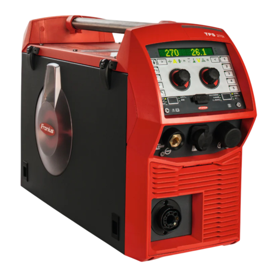
General Device concept The TPS 270i C MIG/MAG power source is a completely digitised, micro- processor-controlled inverter power source with integrated 4-roller wire drive. The modular design and potential for system add-ons ensure a high degree of flexibility. Its compact design makes the TPS 270i C particularly suitable for mobile applications. -
Page 24: Warning Notices On The Device
Warning notices Warning notices and safety symbols are affixed to power sources with the CSA on the device test mark for use in North America (USA and Canada). These warning notices and safety symbols must not be removed or painted over. They warn against in- correct operation, as this may result in serious injury and damage. - Page 25 These Operating Instructions All the Operating Instructions for the system components, especially the safety rules Do not dispose of used devices with domestic waste. Dispose of them according to the safety rules. Keep hands, hair, clothing and tools away from moving parts. For example: Cogs Feed rollers Wirespools and welding wires...
-
Page 26: Description Of The Warning Notices On The Device
Description of For certain device versions, warning notices are affixed to the device. the warning no- tices on the The arrangement of the symbols may vary. device Warning! Attention! The symbols represent possible dangers. Drive rollers can injure fingers. The welding wire and drive parts are live during operation. Keep hands and metal objects away! An electric shock can be fatal. - Page 27 Use forced-air ventilation or a local extraction system to remove welding fumes. Remove welding fumes with a fan. Welding sparks can cause an explosion or fire. Keep flammable materials away from the welding process. Never weld close to flammable materials. Welding sparks can cause a fire.
-
Page 28: System Components
System components General The power sources can be operated with various system components and op- tions. This makes it possible to optimise procedures and to simplify machine handling and operation, as necessitated by the particular field of application in which the power source is to be used. Overview Power source Cooling unit... - Page 29 OPT/i GUN Trigger Option for special functions in conjunction with the torch trigger OPT/i OPC-UA Standardised data interface protocol OPT/i MQTT Standardised data interface protocol...
-
Page 31: Welding Packages, Welding Characteristics And Welding Processes
Welding packages, welding charac- teristics and welding processes... -
Page 33: Welding Packages
Welding packages General Various welding packages, welding characteristics and welding processes are available with TPSi power sources that enable a wide range of materials to be ef- fectively welded. Welding pack- The following welding packages are available for TPSi power sources: ages Standard Welding Package 4,066,012... -
Page 34: Welding Characteristics
Welding characteristics Welding charac- Depending on the welding process and shielding gas mix, various process-optim- teristics ised welding characteristics are available when selecting the filler metal. Examples of welding characteristics: MIG/MAG 3700 PMC Steel 1,0mm M21 - arc blow * MIG/MAG 3450 PMC Steel 1,0mm M21 - dynamic * MIG/MAG 3044 Puls AlMg5 1.2 mm I1 - universal * MIG/MAG 2684 Standard Steel 0.9 mm M22 - root *... - Page 35 cladding CMT, LSC, PMC Characteristics for overlay welding with low penetration, low dilution and wide weld seam flow for improved wetting constant current Constant current characteristic for applications where no arc length control is required (stick out changes are not compensated) CW additive PMC, ConstantWire...
- Page 36 Characteristic with hot start sequence, specifically for plug welds and MIG/MAG spot weld joints 2) / 3) Also required: Pulse and PMC Welding Packages Characteristic for the production of a rippled weld. The heat input into the component is specifically controlled by the cyclical pro- cess change between pulsed and dip transfer arc.
- Page 37 The characteristic changes cyclically between a pulsed or spray arc to a dip transfer arc, depending on the power range. It is especially suitable for vertical- up welds due to the alternating hot and then cold, supporting process phase. Characteristic for welding brads to an electrically conductive surface The retraction movement of the wire electrode and the set current curve pro- gression define the appearance of the pin.
- Page 38 seam track PMC, Pulse Characteristic with amplified current control, especially suitable for the use of a seam tracking system with external current measurement. TIME Characteristic curve for welding with very long stick out and T.I.M.E. shielding gases to increase the deposition rate. (T.I.M.E.
-
Page 39: Welding Methods And Processes
Welding methods and processes MIG/MAG pulse MIG/MAG pulse synergic welding is a pulsed-arc process with controlled materi- synergic welding al transfer. In the base current phase, the energy supply is reduced to such an extent that the arc is only just stable and the surface of the workpiece is preheated. In the pulsing current phase, a precisely dosed current pulse ensures the targeted de- tachment of a droplet of welding material. -
Page 40: Synchropulse Welding
SynchroPulse SynchroPulse is available for all processes (standard/pulsed/LSC/PMC). welding Due to the cyclical change of welding power between two operating points, Syn- chroPulse achieves a flaking seam appearance and non-continuous heat input. CMT process CMT = Cold Metal Transfer A special CMT drive unit is required for the CMT process. The reversing wire movement in the CMT process results in a droplet detachment with improved dip transfer arc properties. - Page 41 ally (e.g. for producing a rippled weld seam, for tacking light-gauge sheets or for longer pause times for simple, automatic spot welding mode). Stitch welding is possible with any operating mode. In special 2-step mode and special 4-step mode, no interval cycles are per- formed during the start and end phases.
-
Page 43: Controls, Connections And Mechanical Components
Controls, connections and mechan- ical components... -
Page 45: Control Panel
Control panel General Welding parameters can be easily changed and selected using the adjusting dial. The parameters are shown on the display while welding is in progress. The synergic function ensures that other welding parameters are also adjusted whenever an individual parameter is changed. NOTE! As a result of firmware updates, you may find that your device has certain func- tions that are not described in these operating instructions, or vice versa. - Page 46 Function Process control parameter indicator For the LSC and PMC welding processes Penetration stabilizer indicator Lights up if the penetration stabilizer is active Arc length stabilizer indicator Lights up when the arc length stabilizer is active Left parameter selection The corresponding indicator lights up when a parameter is selected. The following parameters can be selected by pressing the button: Material thickness * In mm or inches...
- Page 47 Arc length stabilizer The "Penetration stabilizer" and "Arc length stabilizer" process control parameters can only be selected when the LSC/PMC welding process is used. The currently adjustable parameter is marked with an arrow. * Synergic parameter When a synergic parameter is changed, the synergic function automatically changes all other synergic parameters to match.
- Page 48 Pulse/dynamic correction The function varies according to the welding process being used. A de- scription of the various functions can be found in the Welding chapter un- der the corresponding welding process. Special function Any parameter can be assigned to this The function can be selected if a parameter has been saved.
- Page 49 PULS SYNERGIC (MIG/MAG pulse synergic welding) SYNERGIC (MIG/MAG standard synergic welding) MANUAL (MIG/MAG standard manual welding) LSC/PMC (LSC = Low Spatter Control, PMC = Pulse Multi Control) Depending on which function package is enabled STICK/TIG (MMA welding/TIG welding) CMT / SP (CMT welding / special programs) (10) USB port For updating the software using a USB Ethernet adapter...
-
Page 50: Displaying Plain Text For Parameters
Displaying plain The left adjusting dial can be used to display the corresponding plain text for text for paramet- each parameter abbreviation shown on the display. Example: Parameter or entry from the Setup menu has been selected using the right adjusting dial;... -
Page 51: F1/F2 Special Function Parameters, Favourites Button
F1/F2 special function parameters, Favourites button F1 and F2 spe- Setting F1 and F2 special function parameters cial function parameters I-S [%] ~ 3 sec. ~ 3 sec. Example: the selected parameter I-S is assigned to F1 Select the desired parameter in the Setup menu Further information on the Setup menu can be found from page To assign the selected parameter to F1 or F2, press the parameter selection button for approx. -
Page 52: The Favourites Button
Press the parameter selection button until F1 or F2 lights up: F1 ... left parameter selection F2 ... right parameter selection The stored parameter is shown first, then the currently set value of the paramet- Change the value of the parameter by turning the adjusting dial: F1 ... - Page 53 ~ 3 sec. Example: The selected SynchroPulse folder is assigned to the Favourites button Select the desired parameter or the desired parent folder in the Setup menu Further information on the Setup menu can be found from page To assign the selected parameter or folder to the Favourites button, press the Favourites button for approx.
- Page 54 > 5 sec. Press the Favourites button for at least 5 seconds: The stored parameter or folder is deleted and and X are shown on the display: The Favourites button can also be assigned in the Setup menu (page 129).
-
Page 55: Connections, Switches And Mechanical Components
Connections, switches and mechanical compon- ents Connections, Function switches and mechanical com- Control panel with display ponents for operating the power source (+) current socket with bayonet latch Blanking cover reserved for the TMC connec- tion socket of the TIG option Welding torch connection for connecting the welding torch... - Page 56 Function (12) Wirespool holder with brake for holding standard wirespools weighing up to 19 kg (41.89 lb.) and with a max. diameter of 300 mm (11.81 in) (13) 4 roller drive (12) (13) Side view...
-
Page 57: Installation And Commissioning
Installation and commissioning... -
Page 59: Minimum Equipment Needed For Welding Task
Minimum equipment needed for welding task General Depending on which welding process you intend to use, a certain minimum equip- ment level will be needed in order to work with the power source. The welding processes and the minimum equipment levels required for the weld- ing task are then described. -
Page 60: Before Installation And Commissioning
Before installation and commissioning Safety WARNING! Danger from incorrect operation and work that is not carried out properly. This can result in serious personal injury and damage to property. ▶ All the work and functions described in this document must only be carried out by technically trained and qualified personnel. -
Page 61: Generator-Powered Operation
CAUTION! An inadequately dimensioned electrical installation can cause serious damage. ▶ The mains lead and its fuse protection must be dimensioned to suit the local power supply. The technical data shown on the rating plate applies. Generator- The power source is generator-compatible. powered opera- tion The maximum apparent power S... -
Page 62: Connecting The Mains Cable
Connecting the mains cable Safety WARNING! Danger due to work that has been carried out incorrectly. This can result in serious injury and damage to property. ▶ The work described below must only be carried out by trained and qualified personnel. -
Page 63: Connecting The Mains Cable - General
AWG = American wire gauge Connecting the CAUTION! mains cable - general Risk of injury and damage from short circuits. Short circuits can occur between the phase conductors or between the phase conductors and the ground conductor unless ferrules are used. ▶... - Page 64 To route the conductors near to the switch Not to make the conductors unnecessarily long To fit the protective hose supplied over the cable and insert the covered cable into the strain-relief device if cable diameters are small Tightening torque = 1.2 Nm Tightening torque = 1.2 Nm 5 x TX25, tightening torque = 3 Nm 6 x TX25, tightening torque = 3 Nm...
-
Page 65: Start-Up
Start-up Safety WARNING! Danger from electrical current. This can result in serious personal injury and damage to property. ▶ Before starting work, switch off all the devices and components involved and disconnect them from the grid. ▶ Secure all devices and components involved so they cannot be switched back WARNING! Danger of electrical current due to electrically conductive dust in the device. -
Page 66: Establishing A Ground Earth Connection
Establishing a NOTE! ground earth When establishing a ground earth connection, observe the following points: connection ▶ Use a separate return lead cable for each power source ▶ Keep the plus cable and return lead cable together as long and as close as possible ▶... -
Page 67: Connecting The Welding Torch
Connecting the Before connecting the welding torch, check that all cables, lines and hosep- welding torch acks are undamaged and properly insulated. Open the wire-feed unit cover Inserting/repla- In order to achieve optimum wire electrode feed, the feed rollers must be suit- cing feed rollers able for the diameter and alloy of the wire being welded. -
Page 69: Inserting The Wirespool
Inserting the CAUTION! wirespool Danger from springiness of spooled wire electrode. This can result in injuries. ▶ While inserting the wirespool, hold the end of the wire electrode firmly to avoid injuries caused by the wire springing back. CAUTION! Danger of injury and damage from falling wirespool. This can result in injuries. -
Page 70: Inserting The Basket-Type Spool
Inserting the CAUTION! basket-type spool Danger from springiness of spooled wire electrode. This can result in injuries. ▶ While inserting the basket-type spool, hold the end of the wire electrode firmly to avoid injuries caused by the wire springing back. CAUTION! Danger from falling basket-type spool. -
Page 71: Feeding In The Wire Electrode
Feeding in the WARNING! wire electrode Danger from springiness of spooled wire electrode. This can result in serious personal injuries. ▶ Wear safety goggles. ▶ When inserting the wirespool/basket-type spool, hold the end of the wire electrode firmly to avoid injuries caused by the wire electrode springing back. CAUTION! Danger from sharp end of wire electrode. - Page 72 WARNING! Danger due to emerging wire electrode. This can result in serious personal injuries. ▶ Hold the welding torch so that the tip of the welding torch points away from the face and body. ▶ Wear suitable protective goggles. ▶ Do not point the welding torch at people.
-
Page 73: Setting The Contact Pressure
Setting the con- NOTE! tact pressure Set the contact pressure in such a way that the wire electrode is not deformed but nevertheless ensures proper wirefeeding. Contact pressure standard values for U-groove rollers Steel: 4 - 5 CrNi 4 - 5 Tubular cored electrodes 2 - 3 Adjusting the... -
Page 74: Design Of The Brake
STOP Design of the WARNING! brake Danger from incorrect installation. This can result in severe personal in- jury and damage to property. ▶ Do not dismantle the brake. ▶ Maintenance and servicing of brakes is to be carried out by trained, qualified personnel only. -
Page 75: Welding
Welding... -
Page 77: Mig/Mag Modes
MIG/MAG modes General WARNING! Danger from incorrect operation. Possible serious injury and damage to property. ▶ Do not use the functions described here until you have read and completely understood these Operating Instructions. ▶ Do not use the functions described here until you have fully read and under- stood all of the Operating Instructions for the system components, in partic- ular the safety rules! See the Setup menu for information on settings, setting range and units of meas-... -
Page 78: 2-Step Mode
End arc length correction Slope 2: the welding current is steadily lowered until it reaches the final current Gas post-flow Spot welding time A detailed explanation of the parameters can be found in the section headed "Process parameters". 2-step mode "2-step mode"... -
Page 79: Special 4-Step Mode
Special 4-step mode "Special 4-step mode" is particularly suitable for welding aluminium materials. The special slope of the welding current curve takes account of the high thermal conductivity of aluminium. Special 2-step mode "Special 2-step mode" is ideal for welding in the higher power range. In special 2- step mode, the arc starts at a lower power, which makes it easier to stabilise. -
Page 80: Spot Welding
Spot welding The "Spot welding" mode is suitable for welded joints on overlapped sheets. -
Page 81: Mig/Mag And Cmt Welding
MIG/MAG and CMT welding Safety WARNING! Danger from incorrect operation and work that is not carried out properly. This can result in serious personal injury and damage to property. ▶ All the work and functions described in this document must only be carried out by technically trained and qualified personnel. -
Page 82: Retrieving The Currently Set Filler Metal
Press the "Welding process" button until the LED for the desired welding pro- cess lights up Press the "Mode" button until the LED for the desired operating mode lights Retrieving the currently set filler metal Press the "Filler metal info" button The LED on the button lights up and the currently set filler metal is shown on the display: Turn the right adjusting dial... - Page 83 Press the "Filler metal selection" button The LED on the button lights up and "filler metal?" is shown on the display: Press the right adjusting dial The first available filler metal is displayed: Select the desired filler metal by turning the right adjusting dial Press the right adjusting dial "diameter?"...
-
Page 84: Setting The Welding Parameters
Press the right adjusting dial The set filler metal is saved. The previous item can be called up by turning the right adjusting wheel and selecting "back". Setting the 22.8 5O.O welding para- meters Press the button until the desired welding parameter lights up Material thickness Welding current Wire speed... -
Page 85: Set The Shielding Gas Flow Rate
parameters are changed during synergic welding, the remaining welding paramet- ers are immediately altered accordingly. Set the shielding Open the gas cylinder valve gas flow rate Press the gas-test button Gas flows out. The "Gas purging" dialogue window appears on the display, indicating the re- maining gas purging time. -
Page 86: Spot And Stitch Welding
Spot and stitch welding Spot welding Spot welding is used on welded joints on overlapped sheets that are only access- ible on one side. Spot welding can be carried out in the following welding processes: PULSE SYNERGIC | SYNERGIC | MANUAL | LSC/PMC | SP (CMT) Select the desired welding process by pressing the "Welding process"... -
Page 87: Stitch Welding
Hold the welding torch vertical Press and release the torch trigger Keep the welding torch in the same position Wait for the gas post-flow time Raise the welding torch NOTE! Pre-set start of welding and end of welding parameters are also active for spot welding. - Page 88 To end stitch welding, depending on the selected mode: release the torch trigger (2-step mode) press and release the torch trigger (4-step mode) Wait for the gas post-flow time Raise the welding torch Notes on stitch welding With PMC characteristics, the setting of the SFI parameter influences the re-ig- nition behaviour in interval operation: SFI = on Re-ignition takes place with SFI.
-
Page 89: Mig/Mag And Cmt Welding Parameters
MIG/MAG and CMT welding parameters Welding para- The following welding parameters can be set and displayed for MIG/MAG pulse meters for synergic welding and PMC welding: MIG/MAG pulse synergic welding using the left adjusting dial: and PMC weld- Material thickness Setting range: 0.1 - 30.0 mm / 0.004 - 1.18 in. -
Page 90: Welding Parameters For Mig/Mag Standard Synergic Welding, Lsc Welding And Cmt
using the right adjusting dial: Arc length correction for correcting the arc length; Setting range: -10 - +10 Factory setting: 0 - ..shorter arc length 0 ... neutral arc length + ... longer arc length Welding voltage in V Setting range: depends on the welding process and welding program selected Before the start of welding, the device automatically displays a standard value based on the programmed parameters. - Page 91 Material thickness Setting range: 0.1 - 30.0 mm / 0.004 - 1.18 in. Welding current in A Setting range: depends on the welding process and welding program selected Before the start of welding, the device automatically displays a standard value based on the programmed parameters.
- Page 92 Setting range: -10 - +10 Factory setting: 0 - ..shorter arc length 0 ... neutral arc length + ... longer arc length Welding voltage in V Setting range: depends on the welding process and welding program selected Before the start of welding, the device automatically displays a standard value based on the programmed parameters.
-
Page 93: Welding Parameters For Mig/Mag Standard Manual Welding
Welding para- The following welding parameters can be set and displayed for MIG/MAG stand- meters for ard manual welding: MIG/MAG standard manual using the left adjusting dial: welding Wire speed for setting a harder, more stable arc Setting range: 0.5 - 25 m/min / 20 - 980 ipm. - Page 94 ally changes all other synergic parameters to match. The actual setting range depends on the power source and wirefeeder used and on the welding program selected. The actual setting range depends on the welding program selected. The maximum value depends on the wirefeeder used. Only in the LSC and PMC welding processes...
-
Page 95: Easyjob Mode
EasyJob mode General The 5 EasyJob buttons enable up to 5 operating points to be saved quickly. The current welding settings are saved. EasyJob mode ~ 3 sec. < 3 sec. > 5 sec. Storing EasyJob operating points To store the current welding settings, press one of the EasyJob buttons for approx. -
Page 96: Tig Welding
TIG welding Safety WARNING! Danger from incorrect operation and work that is not carried out properly. This can result in serious personal injury and damage to property. ▶ All the work and functions described in this document must only be carried out by technically trained and qualified personnel. - Page 97 IMPORTANT! For optimum welding results, the manufacturer recommends per- forming an R/L alignment when starting the device for the first time and when any changes are made to the welding system. Press the "Welding process" button until the LED for the STICK/TIG welding process lights up and "TIG"...
-
Page 98: Igniting The Arc
Igniting the arc The welding arc is ignited by touching the workpiece with the tungsten electrode. Place the gas nozzle on the ignition location so that there is 2-3 mm (0.08 - 0.12 in.) between the tip of the tungsten electrode and the workpiece. Keep a distance Gradually tilt the welding torch up until the tungsten electrode touches the workpiece... -
Page 99: Mma Welding
MMA welding Safety WARNING! Danger from incorrect operation and work that is not carried out properly. This can result in serious personal injury and damage to property. ▶ All the work and functions described in this document must only be carried out by technically trained and qualified personnel. - Page 100 Move the mains switch to the "I" position IMPORTANT! For optimum welding results, the manufacturer recommends per- forming an R/L alignment when starting the device for the first time and when any changes are made to the welding system. STICK Press the "Welding process"...
-
Page 101: Welding Parameters For Manual Metal Arc Welding
Welding para- The following welding parameters can be set and displayed for manual metal arc meters for welding: manual metal arc welding using the left adjusting dial: Main current in A Setting range: depends on the power source available Before the start of welding, the machine automatically displays a standard value based on the programmed parameters. -
Page 103: Setup Settings
Setup settings... -
Page 105: Setup Menu - Overview
Setup menu - overview Entering/exiting the Setup menu To enter the Setup menu, press the "Welding process" and "Mode" buttons at the same time "Process parameters" is shown on the display. To exit the Setup menu, press the "Welding process" and "Mode" buttons at the same time... -
Page 106: Setup Menu - Overview
Setup menu - overview Process param. Settings Language xx Display System back Start/End Gas-setup Process c. Spot welding Interval (10) (16) Unit CLS [s] (11) (17) Standard Components (12) Web-PWre- STICK (13) UIBS (18) (14) Information DRSL. SynchroPulse F1/F2 Param (19) iJob xx (15) - Page 107 Process parameters Units (16) Duration of interior Language abbreviation (10) metric/imperial lighting Start/end of welding (11) Standards (17) Restore factory settings Process control (12) CEN/AWS (18) Reset password for the Component monitoring (13) Display brightness website Electrode setup (14) Display replaced charac- (19) Mode Setup –...
-
Page 108: Process Parameters
Process parameters Process para- The following process parameters can be set and displayed for the start and end meters for start of welding: of welding/end of welding Starting current For setting the starting current for MIG/MAG welding (e.g. aluminium welding start-up) Setting range: 0 - 200% (of welding current) Factory setting: 135%... - Page 109 End arc length correction For correcting the arc length at the end of welding Setting range: -10 - -0.1 / auto / 0.0 - 10.0 (of welding voltage) Factory setting: 0 - ..shorter arc length 0 ... neutral arc length + ...
-
Page 110: Process Parameters For Gas-Setup
For setting the gas correction factor Setting range: auto / 0.90 - 20.0 Factory setting: auto (the correction factor is automatically set for standard gases from the Fronius welding database) Process para- The following process parameters can be set and displayed for the process con-... - Page 111 Application examples Penetration stabilizer = 0 m/min (not activated) I [A] [m/min] t [s] < s > x Penetration stabilizer = 0 m/min (not activated) Changing the contact tube distance (h) alters the resistance in the welding cir- cuit due to the longer stick out (s The constant voltage control for constant arc length causes a reduction in the mean current value and hence a smaller penetration (x Penetration stabilizer = n m/min (activated)
-
Page 112: Arc Length Stabilizer
I [A] [m/min] 0,5 m/min t [s] < s > x Penetration stabilizer = 0.5 m/min (activated) To minimise the change in welding current if the stick out is changed (s ==> s the wire speed is increased or reduced by 0.5 m/min. In the example shown, the stabilising effect is obtained without a change in cur- rent up to the set value of 0.5 m/min (Position 2). - Page 113 Application examples Arc length stabilizer = 0 / 0.5 / 2.0 Arc length stabilizer = 0 Arc length stabilizer = 0.5 Arc length stabilizer = 2 I [A] [m/min] U [V] t [s] > L > L Arc length stabilizer = 0 / 0.5 / 2.0 Activating the arc length stabilizer reduces the arc length until short circuits start to occur.
-
Page 114: Combination Of Penetration Stabilizer And Arc Length Stabilizer
Combination of Example: Stick out change penetration sta- bilizer and arc Arc length stabilizer without penetration stabilizer length stabilizer The advantages of a short arc are maintained even if the stick out is changed, since the short-circuit prop- erties stay the same. Δs I [A] [m/min]... -
Page 115: Process Parameters For Spot Welding
Process para- meters for spot Spot welding time welding 0.1 - 10.0 s Factory setting: 1.0 s Process para- meters for stitch Interval welding off / on Factory setting: off Int-t Stitch welding time 0.1 - 10.0 s Factory setting: 1.0 s Int-b Interval break time off / 0.1 - 10 s... - Page 116 (only in conjunction with the OPT/i gas controller option) Setting range: auto, 0.90 - 20.0 Factory setting: auto (the correction factor is automatically set for standard gases from the Fronius welding database) Reaction in case of deviation of the wire speed force...
-
Page 117: Process Parameters For Electrode Setup
Setting range: 0.1 - 10.0 s Factory setting: 3.0 s Process para- The following process parameters can be set and displayed for manual metal arc meters for elec- welding (STICK): trode setup Starting current For setting the starting current Setting range: 0 - 200% Factory setting: 150% Starting current time For setting the length of time for which the starting current is to be active... - Page 118 Parameter "0.1 - 20" is used to set a drooping characteristic (5). The setting range extends from 0.1 A / V (very steep) to 20 A / V (very flat). Setting a flat characteristic (5) is only advisable for cellulose electrodes. P-constant (constant welding power) If the "P-constant"...
-
Page 119: Process Parameters For Tig Setup
Anti-stick To activate/deactivate the anti-stick function Setting range: off / on Factory setting: on As the arc becomes shorter, the welding voltage may drop so far that the rod electrode will tend to stick. This may also cause the rod electrode to burn out. The anti-stick function prevents the electrode from burning out. - Page 120 Welding At the end of the welding action, briefly raise the welding torch The arc length is increased significantly. Lower the welding torch The arc length is reduced significantly The TIG Comfort Stop function is triggered Keep the welding torch at the same height The welding current is continuously decreased (downslope).
-
Page 121: Process Parameters For Synchropulse
Process para- The following process parameters can be set for SynchroPulse welding: meters for Syn- Syn-Puls chroPulse SynchroPulse To activate/deactivate SynchroPulse Setting range: off / on Factory setting: off vd (1) Wire speed For setting the average wire speed and therefore the welding power for Syn- chroPulse Setting range: 1.0 - 25.0 m/min (40 - 985 ipm) Factory setting: 5 m/min... - Page 122 - ..short arc 0 ... uncorrected arc length + ... longer arc [m/min] 1 / F 25 % 75 % t [s]...
-
Page 123: Process Parameters For Process Mix
Process para- The following process parameters for mixed processes can be set under "Process meters for Pro- mix": cess Mix PMC mix I [A] [m/min] t [ms] Mixed process between PMC and LSC welding process. A cold LSC process phase follows a hot PMC process phase as part of a cycle. - Page 124 The wire speed value can also be specified or changed in the Process mix para- meters. Arc length correction Is taken from the welding parameters Setting range: -10.0 - +10.0 The arc length correction value can also be specified or changed in the Process mix parameters.
-
Page 125: R/L Alignment
If the lower power time correction is reduced, the process frequency increases and the LSC process phase becomes shorter. Lpc (1) Lower power correction To set the energy input in the cold process phase in a mixed process Setting range: -10.0 - +10.0 Factory setting: 0 If the lower power correction is increased, this results in a higher wire speed and therefore higher energy yield in the cold LSC process phase. - Page 126 Select "Finish" by turning the right adjusting dial Press the right adjusting dial To exit the Setup menu, press the "Welding process" and "Mode" buttons at the same time...
-
Page 127: Settings
Settings General NOTE! As a result of firmware updates, you may find that there are functions available on your device that are not described in these Operating Instructions or vice versa. Certain illustrations may also differ slightly from the actual controls on your device, but these controls function in exactly the same way. -
Page 128: Setting The Standards
Setting the Select Setup menu / Settings / View / Standard standards Press the right adjusting dial The first of the available standards is displayed. Select the desired standard by turning the right adjusting dial: Name of filler metal according to European standards (e.g. -
Page 129: Displaying Replaced Characteristics
Displaying re- Select setup menu / Settings / View / DRSL placed charac- teristics DRSL = Display replaced synergic lines Press the right adjusting dial Select "on" by turning the right adjusting dial Press the right adjusting dial to activate the function To exit the Setup menu, press the "Welding process"... -
Page 130: Retrieving System Data
Retrieving sys- Select Setup menu / Settings / View / System data tem data Press the right adjusting dial The first available system data value is displayed. Select the desired system data value by turning the right adjusting dial To exit the Setup menu, press the "Welding process" and "Mode" buttons at the same time The following system data can be displayed: Current arc power in kW... -
Page 131: Setting The Interior Lighting
Error output if coolant temperature > 70 °C (measured during coolant return) Arc time in h DC-t Total power source operating hours in h Gcon Total gas consumption in l Setting the in- Select Setup menu / Settings / System / CLS terior lighting Press the right adjusting dial Select the desired duration by turning the right adjusting dial:... -
Page 132: Retrieving Device Information
Retrieving Select Setup menu / Settings / System / Information device informa- Press the right adjusting dial tion The first item of available information is displayed. Select the desired information by turning the right adjusting dial Serial number Image version IP address MAC address Press the right adjusting dial to display the information... -
Page 133: Setting The Language
Setting the language Setting the lan- Access the Setup menu guage Select the language Press the right adjusting dial The language abbreviation of the currently set language is highlighted on the dis- play. Select the desired language by turning the right adjusting dial The following languages can be selected: Czech Dutch... -
Page 134: Keylock
Keylock Keylock To activate the keylock Press the "Welding process" and left parameter selection buttons at the same time Alternatively, the "Mode" and right parameter selection buttons can be pressed. The key symbol and a tick are shown on the display: The following functions are dis- The following functions are avail- abled:... -
Page 135: Smartmanager - The Power Source Website
SmartManager - The power source website... -
Page 137: Smartmanager - The Power Source Website
SmartManager - The power source website General The power source has its own website: SmartManager. As soon as the power source is connected to a computer using a network cable, or is on a network, the power source's SmartManager can be retrieved using the power source's IP address. -
Page 138: Settings
Language selec- tion The languages available for SmartManager can be displayed by clicking on the language abbreviation. To change the language, click on the one you would like. Fronius A click on the Fronius logo opens the homepage of Fronius: www.fronius.com. -
Page 139: Current System Data
Current system data Current system The welding system's current data is displayed. data NOTE! The system data displayed will vary depending on the welding process, equip- ment and existing WeldingPackages. ▶ e.g. system data for MIG/MAG: TPS 270i C | Name (10) (11) (12) - Page 140 Device type (17) Wire feed speed set value Device name (18) Arc length correction Factory (19) Pulse/dynamic correction Production building (hall) (20) Arc power Cell (21) Arc length stabilizer Filler (22) Penetration stabilizer Welding process (23) Total shielding gas consump- Actual values / HOLD or aver- tion age values (depending on set-...
-
Page 141: Job-Data
Job-Data Job data The EasyJobs stored on the power source can be viewed in the Job Data entry under Job Overview and exported as a PDF file. -
Page 142: Backup & Restore
Backup & Restore General remarks In the backup & restore entry all welding system data can be saved as a backup (e.g. current parameter set- tings, jobs, user characteristics, defaults, etc.), any backups will be restored to the welding system You can select which data you would like to be backed up automatically. -
Page 143: Automatic Backup
Automatic Enable interval settings backup Enter the intervals at which the automatic backup should take place: Interval: daily / weekly / monthly time (hh:mm) Enter the data for the backup destination: Protocol: SFTP (Secure File Transfer Protocol) / SMB (Server Message Block) Server: Enter IP address of the destination server Port:... -
Page 144: Overview
Overview Overview In the overview entry, welding system components and options are displayed with all available information, e.g. firmware version, item number, serial number, pro- duction date, etc. Expanding / re- Clicking on the button "Expand all groups" displays further details for the indi- ducing all groups vidual system components. -
Page 145: Update
To restart the power source, click on "Yes" The power source restarts; the display goes black for a short time. The Fronius logo is shown on the power source display during the restart. Once the update has been completed successfully, confirmation and the cur- rent firmware version are displayed. -
Page 146: Fronius Weldconnect
Fronius Weld- The mobile application Fronius WeldConnect can also be called up in Connect the "Update" entry. WeldConnect is an app for wireless interaction with the welding sys- tem. The following functions can be performed with WeldConnect: Current unit configuration at a glance... -
Page 147: Function Packages
Function Packages Function pack- The following data can be displayed under function packages: ages Existing Welding Packages on the power source (e.g. WP STANDARD, WP PULSE, WP LSC, etc.) Options available on the power source (OPT/i ...) Installing a Organise and save a function package function pack- Click on "Search function package file"... -
Page 148: Synergic Lines Overview
Synergic lines overview Characteristics In the Characteristics overview entry: overview Available characteristics in the welding system can be displayed: Available characteristics button Possible characteristics in the welding system can be displayed: Possible characteristics button Characteristics for the welding system can be preselected: Characteristic preselection button Saved characteristic preselections can be exported and imported: Export &... -
Page 149: Screenshot
Screenshot Screenshot In the Screenshot entry, a digital image of the power source display can be cre- ated at any time, irrespective of the navigation or set values. Click on "Create screenshot" to capture a screenshot of the display A screenshot of the currently displayed settings is created. Different functions are available for saving the screenshot depending on the browser used;... -
Page 151: Troubleshooting And Maintenance
Troubleshooting and maintenance... -
Page 153: The Error Menu
The Error menu The Error menu Notifications, warnings and errors are shown on the display with the correspond- ing number. If an error occurs, the Error menu is always in the foreground. Pressing the right adjusting dial opens the Error menu on "confirm". Pressing the right adjusting dial a second time confirms the error;... -
Page 154: Care, Maintenance And Disposal
Care, maintenance and disposal General Under normal operating conditions, the power source requires only a minimum of care and maintenance. However, it is vital to observe some important points to ensure the welding system remains in a usable condition for many years. Safety WARNING! Danger from electrical current. -
Page 155: Updating Firmware
IMPORTANT! To update the firmware you need a PC or laptop that is connected ware to the power source via an Ethernet network. Get latest firmware (e.g. from the Fronius Download Center) File format: official_tpsi_x.x.x-xxxx.ffw Establish Ethernet connection between PC/laptop and power source... -
Page 156: Troubleshooting
Troubleshooting General The power sources are equipped with an intelligent safety system, meaning it has been possible to dispense with nearly all fuses. After a possible malfunction has been remedied, the power source can be used again as normal. Possible malfunctions, warning notices or status codes are shown on the display as plain text dialogues. - Page 157 No welding current Mains switch is on, overtemperature is displayed Cause: Overload; the duty cycle has been exceeded Remedy: Check duty cycle Cause: Thermostatic automatic circuit breaker has been tripped Remedy: Wait until the power source automatically comes back on after the end of the cooling phase Cause: Limited supply of cooling air...
- Page 158 Poor weld properties Cause: Incorrect welding parameters Remedy: Check the settings Cause: Poor ground earth connection Remedy: Ensure good contact to workpiece Cause: Inadequate or no protective gas shield Remedy: Check the pressure regulator, gas hose, gas solenoid valve, torch gas connection, etc.
- Page 159 Welding torch becomes very hot Cause: Welding torch is inadequately dimensioned Remedy: Observe the duty cycle and loading limits Cause: Only on water-cooled systems: inadequate coolant flow Remedy: Check coolant level, coolant flow, for coolant contamination, etc. For further information refer to the cooling unit Operating Instructions...
-
Page 161: Technical Data
Technical data... -
Page 163: Average Consumption Values During Welding
Average consumption values during welding Average wire Average wire electrode consumption at a wire speed of 5 m/min electrode con- 1.0 mm wire 1.2 mm wire 1.6 mm wire sumption during electrode dia- electrode dia- electrode dia- MIG/MAG weld- meter meter meter Steel wire electrode... -
Page 164: Technical Data
Technical data Explanation of Duty cycle (ED) is the proportion of time in a 10-minute cycle at which the device the term "duty may be operated at its rated output without overheating. cycle" NOTE! The ED values specified on the rating plate are based on an ambient temperat- ure of 40 °C. -
Page 165: Tps 270I C
TPS 270i C Mains voltage (U 3 x 400 V Max. effective primary current (I 9.7 A 1eff Max. primary current (I 15.3 A 1max Mains fuse 16 A slow-blow Mains voltage tolerance -15 / +15% Grid frequency 50/60 Hz Cos phi (1) 0.99 Max. -
Page 166: Tps 270I C /Nc
Power source efficiency at 270 A / 30.8 V The wirefeeder for the TPS 270i C is integrated in the power source. Interface to a 230/400 V and 50 Hz public grid TPS 270i C /nc Mains voltage (U 3 x 380 / 400 / 460 V Max. -
Page 167: Tps 270I C /Mv/Nc
Wire speed 1 - 25 m/min 40 - 980 ipm Wire drive 4-roller drive Wire diameter 0.8 - 1.6 mm 0.03 - 0.06 in. Wirespool diameter max. 300 mm max. 11.8 in. Wirespool weight max. 19.0 kg max. 41.9 lb. Idle state power consumption at 400 31 W Power source efficiency... - Page 168 Output voltage range according to standard characteristic (U 14.2 - 27.5 V MIG / MAG 14.1 - 20.8 V 20.4 - 30.8 V Rod electrode Open circuit voltage (U peak/U 66 V r.m.s) Protection class IP 23 EMC emission class Dimensions L x W x H 687 x 276 x 445 mm 27.0 x 10.9 x 17.5 in.
-
Page 169: Tps 270I C /S/Nc
TPS 270i C /S/nc Mains voltage (U 3 x 460 / 575 V Max. effective primary current(I 1eff 9.1 A 3 x 460 V 7.2 A 3 x 575 V Max. primary current (I 1max 14.3 A 3 x 460 V 11.4 A 3 x 575 V Mains fuse... -
Page 170: Overview With Critical Raw Materials, Year Of Production Of The Device
An overview of which critical raw materials are contained in this device can be terials, year of found at the following Internet address. production of www.fronius.com/en/about-fronius/sustainability. the device To calculate the year of production of the device: Each device is provided with a serial number...
Need help?
Do you have a question about the TPS/i COMPACT and is the answer not in the manual?
Questions and answers