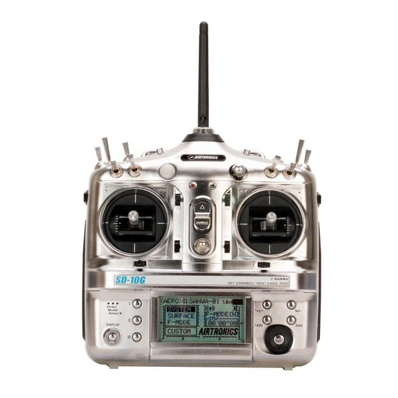
AIRTRONICS SD-10G Operating Manual
2.4ghz fhss-3
Hide thumbs
Also See for SD-10G:
- Setup manual (41 pages) ,
- Operating manual (24 pages) ,
- Manual (16 pages)
Table of Contents
Advertisement
Quick Links
Advertisement
Chapters
Table of Contents

Related Manuals for AIRTRONICS SD-10G


Summary of Contents for AIRTRONICS SD-10G
- Page 1 Page 1...
-
Page 2: Table Of Contents
210 packaging The packaging of your Airtronics SD-10G 2.4GHz FHSS-3 radio control system has been specially designed for the safe transportation and storage of the radio control system's components. after unpacking your radio control system, do not discard the packaging materials. -
Page 3: Introduction
We appreciate your purchase of the new Airtronics SD-10G 2.4GHz FHSS-3 radio control system. This Operating Manual is intended to acquaint you with the many unique features of your new state of the art SD-10G 2.4GHz FHSS-3 radio control system. In designing the SD-10G 2.4GHz FHSS-3 radio control system, our engineers listened to input from our test-pilots and feedback from our users to design a radio control system that will allow you to extract the maximum performance from your model, while at the same time making the programming process as easy as possible to accomplish. -
Page 4: Safety And Usage Precautions
In addition to the FCC Compliance section on the previous page, please observe the following safety and usage precautions when installing and using your new Airtronics SD-10G 2.4GHz FHSS-3 radio control system. SaFETY Be certain to read this Operating Manual in its entirety. -
Page 5: Receiver Precautions
Reception can be blocked if the antenna reception wires are shielded inside a carbon fiber fuselage. The manufacturer disclaims all responsibility for damages resulting from use of components other than genuine Airtronics components. -
Page 6: Features And Specifications
Optional 'Stiff' Control Springs to Fine-Tune Gimbals Optional Throttle Stick Stops Full-Range 92104 10-Channel 2.4GHz FHSS-3 Receiver Compatible with Airtronics 2.4GHz FHSS-1 Aircraft Receivers User Naming, Model Naming and Model Select FHSS-1, FHSS-3, and PPM-8 Modulation Selection 6 Cell 1500mAH Rechargeable Ni-MH Transmitter Battery... - Page 7 If you use analog servos and experience problems, you will need to either upgrade to digital servos or use one of the available Airtronics 2.4GHz FHSS-1 aircraft receivers.
-
Page 8: Basic Model Setup Order
The information on this page describes the Basic Model Setup Order that you can use to setup a new model. Regardless of the model you are flying, using the basic functions of the SD-10G transmitter for most applications is easy and will get your model setup quickly. -
Page 9: Tips And Suggestions
To view our expanding library of specific transmitter setup sheets, visit the SD-10G section of our website at http://www.airtronics.net. Available transmitter setup sheets are saved in PDF format and bundled in a .zip file. - Page 10 Unless otherwise noted, all programming changes take effect immediately. When the Memory Expansion Card is installed and Initialized, it is treated as an extension of the SD-10G transmitter's internal model memory, therefore, model-specific programming data can be created, copied, deleted, etc., directly through the various System menu selections.
-
Page 11: Features Familiarization
TRanSMiTTER cOnTROL FEaTURES DiagRaMS Use the diagrams below to familiarize yourself with the different control features of your new SD-10G transmitter. Descriptions of these features can be found on pages 12 through 13. The features referenced below are general in nature. Features specific to the Model Type (aircraft, helicopter, or sailplane) can be found in those specific sections of this Operating Manual. - Page 12 REcEivER FEaTURES DiagRaMS Use the diagram below to familiarize yourself with the 92104 10-Channel receiver included with your new SD-10G 2.4GHz FHSS-3 radio control system. Descriptions of these features can be found below. Coaxial Cables Bind LED All receiver channel assignments can be programmed to suit the user.
-
Page 13: Servo Connectors
DIN Connector: The DIN Connector is where the trainer cable (available separately) is plugged into. It is also used to plug the Airtronics USB data cable (available separately) between the transmitter and your computer. An adapter to use the transmitter with a flight simulator can also be plugged into the DIN Connector. -
Page 14: Transmitter Alarms
THROTTLE HigH waRning aLaRM The SD-10G transmitter is equipped with a safety feature that will not allow you to use the transmitter if the throttle control stick is not in the lowest position when you turn the transmitter ON. If the throttle control stick is not in the lowest position when you turn the transmitter ON, the Throttle High Warning alarm will sound continuously, the red RF Output Indicator will blink, and the LCD Display will read TH-STICK Hi !! To clear the Throttle High Warning, pull the throttle control stick down to the lowest position. -
Page 15: Custom Transmitter Adjustments
ADJUSTMENTS Every effort has been made to engineer the optimum transmitter weight, balance, and feel in the design of your SD-10G 2.4GHz FHSS-3 radio control system. For example, the transmitter control sticks are ball bearing-supported for smooth control and use springs that result in superior feel for most pilots. - Page 16 MEMORY ExpanSiOn caRD The Memory Expansion Card allows you to store up to 40 models (20 in the SD-10G transmitter and 20 on the Memory Expansion Card). The Memory Expansion Card can be removed and installed into a different SD-10G transmitter, so that model-specific programming data can be shared with fellow SD-10G transmitter owners in the field.
- Page 17 THROTTLE STick STOpS The SD-10G 2.4GHz FHSS-3 radio control system includes two throttle stick stops which can be installed to limit the physical travel of the throttle control stick. In the default configuration, both control sticks move up and down the same amount. Some users, particularly helictopter pilots, prefer it when the physical travel of the throttle control stick is less than that of the other control stick.
- Page 18 custom transmitter ADJUSTMENTS 4) Working with one Auxiliary Lever at a time, carefully pull it up and out of the transmitter case, being careful not to damage the connected wiring. 5) While holding the Auxiliary Lever mounting tabs (C) firmly between your thumb and index finger, grasp and gently pull the lever off of the mount.
-
Page 19: Charging The Battery
The SD-10G 2.4GHz FHSS-3 transmitter features a 6 cell 7.2v 1500mAH Ni-MH battery for lighter weight and longer battery life. The battery is charged directly through the SD-10G transmitter, using the charging jack located in the left side of the SD-10G transmitter. -
Page 20: Airborne System Connections
airborne system connections Use the diagram below to familiarize yourself with how to connect the switch harness, servos, and receiver battery to your 92104 10-Channel receiver. A receiver battery is not included. The receiver can be powered by a 4.8v (4 cell Ni-MH or Ni-Cd) or a 6.0v (5 cell Ni-MH or Ni-Cd) battery pack of desired capacity. -
Page 21: Lcd Display And Programming Keys
LCD display and programming keys The SD-10G 2.4GHz FHSS-3 transmitter features three Programming Keys, an F-MODE key, and a Navigation Pad and ENTER Key, all used in conjunction to facilitate programming. This section summarizes the functions of these features in addition to detailing the main areas of the LCD Display. - Page 22 LCD display and programming keys LcD DiSpLaY OvERviEw Use the diagram below to familiarize yourself with the layout and different indicators that make up the LCD Display. Memory Card RF Output Status Model Number Status Trainer Model Type Model Name Status Voltage Key Mute Status...
-
Page 23: Transmitter And Receiver Binding
A Safety Link function is featured which can be used to program a unique bind code to each receiver/model pair, preventing the transmitter from controlling a model that it's not currently programmed for. Although the SD-10G transmitter can be used with any Airtronics FHSS-1 2.4GHz aircraft receiver, the Safety Link feature is not supported. -
Page 24: Mounting The Receiver
mounting the receiver When mounting the receiver in your model, it's important to mount the receiver exactly as described. In addition, the receiver should be wrapped in foam rubber to protect it from vibration. Failure to mount the receiver antenna wires as described can result in poor reception, or in some cases, complete loss of reception. -
Page 25: Range Checking (Low Power Mode)
If, after checking all airborne system components and verifying correct antenna wire mounting, your radio control system still fails the Range Check, DO NOT FLY. Please contact Airtronics Customer Service. Page 25... -
Page 26: Fail Safe
This section describes the Fail Safe function setup for the 92104 FHSS-3 receiver included with the SD-10G radio control system. For Fail Safe function setup for use with Airtronics 2.4GHz FHSS-1 aircraft receivers, see page 38. -
Page 27: System Menu Contents
system MENU contents System Menu Flow chart ..............................page 28 general information ................................. page 29 USER naME (Transmitter User naming) ........................page 29 MODEL naME (Model naming) ............................page 30 MODEL SELEcT (Model Selection) ..........................page 30 DiREcT MODEL SELEcT (Direct Model Selection) ....................... page 31 TYpE (Model Type - aero, glider, and Heli) ........................ -
Page 28: System Menu
SYSTEM MENU The System menu is where all transmitter-specific programming takes place. Use this menu to make changes to Model Name, Model Select, Model Type, Modulation, Switch Assignments, and much more. System menu selections are the same for all three Model Types. A small number of sub-menu selections vary by Model Type. -
Page 29: General Information
SYSTEM MENU gEnERaL inFORMaTiOn To access the System menu, turn the transmitter ON. Verify that SYSTEM is highlighted, then press the ENTER key to display the System menu. From within any menu, press the END key continuously to return to the Top menu. -
Page 30: Model Name (Model Naming)
SYSTEM MENU 02.MODEL naME (MODEL naMing) The Model Name function allows you to name each of your individual models. This makes it easy to keep track of multiple models. When you select a model, all of the programming for that model is loaded. The Model Name can consist of up to 8 letters, numbers, or symbols. -
Page 31: Direct Model Select (Direct Model Selection)
SYSTEM MENU 04.DiREcT MODEL SELEcT (DiREcT MODEL SELEcTiOn) The Direct Model Select function allows you to select one of three of your most-used models from memory without going through the Model Select menu. This makes it much quicker and easier to load the programming for your three favorite models. Designating a Favorite Model 1) Press the Navigation Pad 56 to highlight DIRECT MODEL SELECT, then press the ENTER key to display the DIRECT MODEL SELECT menu. - Page 32 SYSTEM MENU Making AERO Selection Options Choose AERO selection options that suit the aircraft that you're setting up. For example, if your aircraft is a flying wing and is controlled by elevons, choose WING>DELTA. If your aircraft features separate aileron servos and split elevator halves that use one elevator servo on each elevator half, choose AILERON>2 and TAIL>2xEL, and so on.
- Page 33 SYSTEM MENU Making HELICOPTER Selection Options Choose the HELI Swashplate Type that suits your helicopter. There are three basic Swashplate Types available: Normal - In this configuration the swashplate does not control pitch. It only controls right, left, fore, and aft cyclic. Usually the servos are installed 90º...
-
Page 34: Modulation (Modulation Type, Safety Link, And Binding)
The following Modulation Type options are available: FH1 - Select this Modulation Type when using the SD-10G transmitter with an Airtronics 2.4GHz FHSS-1 aircraft receiver. FH3 - Select this Modulation Type when using the SD-10G transmitter with an Airtronics 2.4GHz FHSS-3 receiver. - Page 35 Before binding the transmitter and receiver, verify that the Modulation and Safety Link settings are accurate for the receiver type you're using. IMPORTANT The SD-10G transmitter is compatible with FHSS-3 and FHSS-1 Airtronics 2.4GHz aircraft receivers. To bind the transmitter to an FHSS-1 receiver, the transmitter modulation must first be changed to FH1.
-
Page 36: Low Power Mode (Range Check Mode)
If, after checking all airborne system components and verifying correct antenna wire mounting, your radio control system still fails the Range Check, DO NOT FLY. Please contact Airtronics Customer Service. Page 36... -
Page 37: Fail Safe (Transmitter Fail Safe)
This section describes the Fail Safe function setup for the 92104 FHSS-3 receiver included with the SD-10G radio control system. For Fail Safe function setup for use with Airtronics 2.4GHz FHSS-1 aircraft receivers, see page 38. -
Page 38: Battery Fail Safe (Receiver Battery Voltage Alarm)
Using the Fail Safe Function with FHSS-1 Receivers If you are using the SD-10G transmitter with an FHSS-1 receiver, the Fail Safe setup procedures described previously do not apply. Use the procedures described below to utilize the Fail Safe function with your FHSS-1 receiver. -
Page 39: Trainer (Trainer System)
Instructor releases the Trainer Switch and control of the model returns instantly to the Instructor. In addition, when the SD-10G transmitter is set to MASTER mode, the option of Activating or Inhibiting the four basic flight controls of the Student's transmitter can be made. When a control stick is Inhibited, that specific control surface cannot be operated by the Student. - Page 40 SYSTEM MENU Inhibiting Control Sticks When the transmitter is set to MASTER mode, the option of Activating or Inhibiting the four basic flight controls of the Student's transmitter can be made. When a control stick is Inhibited, that specific control surface cannot be operated by the Student. This is useful when the Instructor does not want the Student to worry about using one or more controls.
-
Page 41: Mode Setup (Stick Modes And Calibration)
11.MODE SETUp (STick MODES anD caLiBRaTiOn) The Mode Setup function allows you to change the SD-10G transmitter's Operating Modes. Four Operating Modes are available as shown in the table below. The Mode Setup function also includes a Neutral/Travel function that allows you to calibrate the control sticks to ensure accurate control centering, regardless of servo brand used. - Page 42 If you do not feel comfortable making these changes, please send the transmitter to Airtronics Customer Service where this procedure can be completed for a small fee.
- Page 43 Different brands of servos center differently, so if you use a different brand of servos, or mix different brands of servos with Airtronics servos, the Neutral position should be recalibrated to ensure optimum centering. Some pilots prefer to use Stick Stops to limit the movement of the control sticks. The Travel function allows you to adjust the servos to move 100% of their maximum travel if you choose to limit the movement of the control sticks.
-
Page 44: Channel Assign (Receiver Channel Assignments)
SYSTEM MENU 6) The RU-STK LEFT END prompt will be displayed. Move the rudder control stick completely to the left, then press the ENTER key. 7) Follow the prompts to calibrate the remaining control stick movements, making sure to press the ENTER key after each control stick movement to continue to the next prompt. -
Page 45: Switch Assign (Transmitter Switch Assignments)
SYSTEM MENU 2) Press the Navigation Pad 5634 to move the cursor to the channel number you would like to change the Control function of, for example, CH05>GE. 3) Press the YES/+ or NO/- keys to change the Control function associated with the highlighted channel number. - Page 46 SYSTEM MENU Switches are assigned based on function and number. Notice that all transmitter switches have a number that corresponds to the switches position. This Switch Position Number is what is changed in the SW ASSIGN menu to assign the switch to a particular function.
- Page 47 SYSTEM MENU A description of each of the available Switch Assignment functions, along with the default Switch Position Numbers for the AERO, GLID, AND HELI model types are shown in the table below. Functions that are blacked out are not relevant to that Model Type and functions that are blank are available, but are not assigned to a Switch Position Number.
-
Page 48: Stick Switch (Stick Switch Assignments)
SYSTEM MENU 14.STick SwiTcH (STick SwiTcH aSSignMEnTS) The Stick Switch function allows you to convert one or more control stick axes into a switch (Stick Switch), then assign a function to that Stick Switch, using the procedures in the SW ASSIGN menu section. For example, if you are flying a glider that features spoilers, you can assign the Flap function to the throttle control stick. -
Page 49: Timer (Stopwatch, Rhythm, Integral, And System Timers)
SYSTEM MENU 15.TiMER (STOpwaTcH, RHYTHM, inTEgRaL, anD SYSTEM TiMERS) The Timer function consists of four different types of timers. A Stopwatch timer, a Rhythm timer, an Integral timer, and a System timer. The Stop Watch timer and the Rhythm timer can be programmed separately for each individual model. The Stop Watch timer, the Integral timer, and the System timer status can each be displayed on the Top menu. - Page 50 SYSTEM MENU Rhythm Timer The Rhythm timer can be programmed to provided a selected sequence of audible tones, which can be used for pacing aerobatics or for practicing precision landings. Three separate Rhythm timers can be programmed and each Rhythm timer can be turned ON separately by assigning them to different switch positions.
- Page 51 Integral Timer The Integral timer is a Count Up timer that displays the time that the SD-10G transmitter has been turned ON (either via the Power switch or the Display key) since the last time the Integral timer was Reset. The Integral timer is not model-specific, so, for example, it is good to use as an indicator to chart the usage time between battery charges.
-
Page 52: Data Copy (Model Programming Data Copy)
System Timer The System timer is a Count Up timer that displays the total time that the SD-10G transmitter has been turned ON (either via the Power switch or the Display key) since it was new. The System timer cannot be Reset. - Page 53 SYSTEM MENU 2) Press the Navigation Pad 6 to highlight the upper model dialog box. The currently selected model will be displayed. Press the YES/+ or NO/- keys to select the model you would like to copy the programming data FROM. 3) Press the Navigation Pad 6 to highlight the lower model dialog box, then press the YES/+ or NO/- keys to select the model you would like to copy the programming data TO.
-
Page 54: Data Reset (Model Programming Data Reset)
SYSTEM MENU 4) Press the Navigation Pad 6 to highlight the lower model group dialog box, then press the YES/+ or NO/- keys to select the group of ten models you would like to copy the programming data TO. It's not possible to copy the programming data from one model group to the same model group. If you attempt to execute this, SAME MODEL?? will be displayed and the process will not execute. -
Page 55: Data Transfer (Model Programming Data Transfer)
SD-10G transmitter must be connected to the PC using the USB adapter cable. One side of the USB adapter cable plugs into a USB port on your PC and the other side plugs into the DIN connector on the back of the SD-10G transmitter. -
Page 56: Contrast (Lcd Menu Contrast)
If there is a problem with the Data Transfer procedure, for example, if the SD-10G transmitter is not connected to your PC, TIMEOUT ERROR will be displayed. If this occurs, press the any key to return to the Data Transfer menu. -
Page 57: Click (Key-Press Audible Tones)
SYSTEM MENU 20.cLick (kEY-pRESS aUDiBLE TOnES) The Click function allows you to set the audible key tones ON (ACT) or OFF (INH). Setting Click (Audible Key Tone) 1) Press the Navigation Pad 56 to highlight CLICK, then press the ENTER key to display the CLICK menu. The cursor will default to CLICK>ACT. - Page 58 SYSTEM MENU Choosing Shortcut Menu Options 1) Press the Navigation Pad 56 to highlight TOP MENU ARRANGE, then press the ENTER key to display the TOP MENU ARRANGE menu. The cursor will default to MENU>CUSTOM MENU. 2) Press the YES/+ or NO/- keys to choose which Menu shortcut option you would like to be displayed in the Shortcut menu.
-
Page 59: Custom Menu (Custom Menu Display)
The Memory Pack function allows you to utilize the Memory Expansion Card* which allows you to store up to 40 models (20 in the SD-10G transmitter and 20 on the Memory Expansion Card). Use the Memory Pack function to Initialize either a new or a previously used Memory Expansion Card, and to view a List of the models currently saved to the Memory Expansion Card. - Page 60 3) Make sure that the SD-10G transmitter is turned OFF, then carefully install the Memory Expansion Card, making sure that the tab on the bottom of the Memory Expansion Card lines up with the groove in the Memory Expansion Card slot and that the mounting pins line up with the pin receptacle.
-
Page 61: System Information (System Software Update)
SD-10G transmitter must be connected to the PC using the USB adapter cable. One side of the USB adapter cable plugs into a USB port on your PC and the other side plugs into the DIN connector on the back of the SD-10G transmitter. -
Page 62: Surface Menu Contents
surface MENU CONTENTS general information ................................. page 63 REv (Servo Reversing - all Model Types) ........................page 64 cEnT (Servo centering - all Model Types) ........................page 64 Epa (Servo End point adjustment - all Model Types) ....................page 65 LMT (Servo Maximum Travel Limit - all Model Types) .................... -
Page 63: Surface Menu
surface MENU The Surface menu is where all basic adjustments to the control surfaces of your model are made. Adjustment Options include Reversing, Centering, End Point Adjustments, Limits, and CCPM and Swashplate settings (HELI Model Type), in an easy-to-follow spreadsheet format. Individual Adjustment Options can also be 'locked' to prevent unwanted or accidental changes. -
Page 64: Rev (Servo Reversing - All Model Types)
Trim 2 The SD-10G transmitter features Digital Trim Memory. Any amount of trim that you set during flight, using either the trim switches or the YES/+ and NO/- keys from within the Trim menu, is automatically stored in memory for that specific channel and model, and for that specific Flight Mode (if enabled). -
Page 65: Epa (Servo End Point Adjustment - All Model Types)
CENT setting range is -150% to 150%. The default setting is 0%. Increase or decrease the CENT Adjustment Values to center the servo horn. The SD-10G transmitter utilizes Parallel Trim Technology. This allows you to change the CENT Adjustment Values to center the servo horn and still maintain full servo travel (up to 150%) in each direction. -
Page 66: Lmt (Servo Maximum Travel Limit - All Model Types)
surface MENU The tables below show the End Point Adjustment travel direction options for the Default channel for each Model Type. Channels will vary based on current Model Type and specific Model Type selection options. End Point Adjustment values for the Flap channel and the Auxiliary channels can be set individually for all three Switch Positions. AERO GLID HELI... -
Page 67: Cepa (Ccpm Servo End Point Adjustment - Heli Model Type Only)
surface MENU Changing Limit Adjustment Values - Low 1) Press the Navigation Pad 3456 to highlight the LIMT L Adjustment Value for the channel that you would like to change. 2) Press the YES/+ or NO/- keys to change the LIMT L Adjustment Value. 3) Adjust the desired remaining LMT L Adjustment Value using the same techniques. - Page 68 surface MENU 2) Press the ENTER key to display the <SET>CLNR menu. ACT/INH will be highlighted and <INH> (Inhibited) will be selected by default. IMPORTANT Prior to starting to use the Read Offset function below, the elevator, aileron, and pitch servos MUST be centered (servo arms set to 90º) and the Servo Reversing settings should be made, using the CENT and REV functions.
-
Page 69: Cdly (Cp3 Channel Delay - Heli Model Type Only)
surface MENU cDLY (cp3 cHannEL DELaY - HELi MODEL TYpE OnLY) The CP3 Delay function allows you to slow down the two forward channels when using CCPM. For example, on some helicopters, when using CCPM you will find that the elevator is a little more sensitive than the ailerons. You can use the CP3 Delay function to slow down the two forward channels to fine-tune the feel of the swashplate controls. -
Page 70: Swh (Swashplate Setup - Heli Model Type Only)
surface MENU SwH (SwaSHpLaTE SETUp - HELi MODEL TYpE OnLY) The Swash function allows you to control a number of different functions related to the swashplate. Using the Swash function, you are able to reverse individual elevator, aileron, and pitch functions. For example, even if you select the correct Swashplate Type for your particular helicopter there may be a situation where instead of the swashplate rising for positive collective it may be necessary for the swashplate to fall for positive collective. -
Page 71: Flight Modes
FLigHT MODE waRning aLaRM The SD-10G transmitter is equipped with a safety feature that will not allow you to use the transmitter if the Flight Mode is not set to 'N' (Normal) when you turn the transmitter ON. If the Flight Mode is not set to 'N' when you turn the transmitter ON, the Flight... -
Page 72: Aero Flight Mode Contents
aero Flight Mode Contents general information ................................. page 73 aERO Flight Mode Menu Flow chart ..........................page 73 aERO Model Type Default Transmitter Layout ......................page 74 Sx MOniTOR (Servo Monitor) ............................page 75 STick MOniTOR (control Stick Monitor) ........................page 76 D/R (Dual Rate - Elevator, aileron, and Rudder) ...................... -
Page 73: Aero Flight Mode Menu
aero Flight Mode Menu gEnERaL inFORMaTiOn To access the F-Mode menu, turn the transmitter ON. From the Top menu, press the Navigation Pad 56 to highlight F-MODE, then press the ENTER key to display the F-Mode menu. From within any menu, press the END key continuously to return to the Top menu. -
Page 74: Aero Model Type Default Transmitter Layout
aero Flight Mode menu aERO MODEL TYpE DEFaULT TRanSMiTTER LaYOUT The diagrams below show the default transmitter control stick and switch layout in the AERO Model Type Flight Mode N (Normal) configuration. This is the base from which you can start to change or add functions to switch assignments, modify Flight Modes, and change or assign functions or channels to the Auxiliary Levers (VR5 and VR6) and the Auxiliary Dial (VR7). -
Page 75: Sx Monitor (Servo Monitor)
SD-10G transmitter actually transmitting a signal. When both the SD-10G transmitter and the receiver are turned ON, the Servo Monitor function has the ability to continuously cycle the primary flight control servos back and forth to verify operation. You are also able to individually cycle any of the primary flight control servos and check the Neutral position of each of the servos (or automatically center all of the servos). -
Page 76: Stick Monitor (Control Stick Monitor)
1) Press the Navigation Pad 56 to highlight STICK MONITOR, then press the ENTER key to display the STICK MONITOR menu. The current Mode that the SD-10G transmitter is operating in will be displayed. 2) Move the control sticks and watch the percentage displays. When the... -
Page 77: Exp (Exponential - Elevator, Aileron, And Rudder)
aero Flight Mode Menu Choosing the Channel 1) Press the Navigation Pad 56 to highlight CH>EL. 2) If you would like to set the Dual Rate for another channel, press the YES/+ or NO/- keys to choose CH>AI or CH>RU. Dual Rate can be set for EL (Elevator), AI (Aileron), and RU (Rudder). - Page 78 aero Flight Mode menu Exponential does not change the total amount of servo travel at maximum control stick deflection. Exponential affects the ratio between servo travel and control stick movement at less than 100% control stick deflection. Choosing the Flight Mode 1) Press the Navigation Pad 56 to highlight EXP, then press the ENTER key to display the EXP menu.
-
Page 79: Th-Curve (Throttle Curve)
The Throttle Curve function is also extremely useful when setting up a twin-engine aircraft. In a twin-engine aircraft, it can be difficult to achieve the exact same throttle response for both engines. The SD-10G transmitter allows you adjust the Throttle Curve for the Right and Left engines separately. - Page 80 aero Flight Mode menu Choosing the Channel This option is only available when Model Type Setting Option THROTTLE>2 is chosen. Unless you are setting up a multi-engine aircraft, skip to the Setting Throttle Curve Point and Rate section below. 1) Press the Navigation Pad 56 to highlight CH>LT. 2) If you would like to set the Throttle Curve for the Right Throttle, press the YES/+ or NO/- keys to choose CH>RT.
-
Page 81: Th-Hold (Throttle Hold)
The Throttle Hold function allows you to set a specific position that the throttle servo will Hold and not respond to the throttle control stick. This function is typically used when flying twin-engine aircraft. The SD-10G transmitter allows you program Throttle Hold for the Right or the Left engine separately. -
Page 82: Th-Cut (Throttle Cut)
For example, if your engine idles when the throttle control stick is at the -100% position, you can set the Throttle Cut to -120% to shut down your engine when the Throttle Cut function is Activated. The SD-10G transmitter allows you to program the Throttle Cut percentage values for the Right and the Left engines independently to take into account any differences between throttle linkages. -
Page 83: Idle Down (Throttle Idle Down)
aero Flight Mode Menu 1) Press the Navigation Pad 6 to highlight TH>-100%. 2) Press the YES/+ or NO/- keys to set the position you would like the throttle servo to move to when TH-CUT is Activated. When the Throttle Cut function is Activated, the throttle control stick will be disabled. -
Page 84: Ai Differential (Aileron Differential)
aero Flight Mode menu 1) Press the Navigation Pad 56 to highlight IDLE DOWN, then press the ENTER key to display the IDLE DOWN menu. The cursor will default to COMMON>COM. 2) Press the YES/+ or NO/- keys to choose either COM or SEP. If set to COM, skip to the Setting the Idle Down percentage value section. -
Page 85: Offset (Channel Offset - Elevator, Aileron, And Rudder)
aero Flight Mode Menu Choosing the Flight Mode 1) Press the Navigation Pad 56 to highlight AI DIFFERENTIAL, then press the ENTER key to display the AI-DIFF menu. The cursor will default to LA-L>100%. 2) Press the F-MODE key to choose the F-MODE number you would like to program the Aileron Differential function for. -
Page 86: Delay (Channel Servo Delay)
aero Flight Mode menu Choosing the Flight Mode 1) Press the Navigation Pad 56 to highlight OFFSET, then press the ENTER key to display the OFFSET menu. The cursor will default to EL>0%. 2) Press the F-MODE key to choose the F-MODE number you would like to program the Offset function for. - Page 87 aero Flight Mode Menu Transmitter F-MODE Programming F-MODE Transmitter F-MODE refers to the Flight Mode that the transmitter is currently operating in. Programming F-MODE refers to the Flight Mode that you would like to change the programming for. IMPORTANT Each CH-DELAY function (CH-DELAY 1, 2, 3, 4, and 5) must be assigned to a Switch Position Number before it can be Activated.
- Page 88 aero Flight Mode menu Changing the Symmetry Value 1) Press the Navigation Pad 6 to highlight SYMMETRY>YES, then press the YES/+ or NO/- keys to change the Symmetry option. The following Symmetry options are available: YES - Selecting this option results in the NO - Selecting this option results in the Channel Delay function affecting the speed Channel Delay function affecting the speed...
-
Page 89: Trim (Control Surface Trim)
Flight Modes. The SD-10G transmitter features Digital Trim Memory. Any amount of trim that you set during flight, using either the trim switches or the YES/+ and NO/- keys from within the Trim menu, is automatically stored in memory for that specific channel and model, and for that specific Flight Mode (if enabled). -
Page 90: Trim Step
aero Flight Mode menu 1) Press the Navigation Pad 3456 to highlight the channel you would like to change the Trim percentage value for, then press the YES/+ or NO/- keys to change the Trim percentage value. TRIM setting range is -150% to 150%. The default setting is 0%. Press the YES/+ and NO/- keys at the same time to set the Trim percentage value to 0% for the selected channel. -
Page 91: Trim Auth (Trim Authority Flap 1 Vr Auxiliary Lever Override)
aero Flight Mode Menu 14.TRiM aUTH (TRiM aUTHORiTY FLap 1 vR aUxiLiaRY LEvER OvERRiDE) The Trim Authority function allows you to control the flap channel using one of the Auxiliary Levers (VR5 or VR6) or the Auxiliary Dial (VR7) when the flap switch is in Flap Position 1. In the default configuration, this function is assigned to Auxiliary Lever (VR6). This allows you not only to have the option of using the three-position flap switch to control the flaps, but also the option of using an auxiliary lever to variably control the flaps. -
Page 92: Cross-Trim (Control Surface Cross-Trim)
aero Flight Mode menu IMPORTANT In the default configuration, Auxiliary Lever (VR6) variably controls the flap channel when the flap switch is in Flap Position 1. Prior to setting your flap End Point Adjustments in the Surface menu, make sure that Auxiliary Lever (VR6) is centered. 1) Press the Navigation Pad 6 to highlight FL1 TRIM>100%, then press the YES/+ or NO/- keys to change the FL1 TRIM percentage value. -
Page 93: Snap Roll (Snap Roll)
aero Flight Mode Menu Changing the Throttle/Elevator Cross-Trim 1) Press the Navigation Pad 6 to highlight TH 34 EL>INH, then press the YES/+ or NO/- keys to change the TH 34 EL Cross-Trim setting. CROSS-TRIM setting range is INH/ACT. The default setting is INH. When Activated, the throttle trim switch will control the elevator trim and the elevator trim switch will control the throttle trim. - Page 94 aero Flight Mode menu Choosing the Flight Mode - Common or Separate When set to COM (Common), the SNAP ROLL settings will be the same regardless of which Flight Mode the transmitter is operating in. You cannot program SNAP ROLL settings separately for each Flight Mode. When set to SEP (Separate), you can program different SNAP ROLL settings separately for each Flight Mode.
-
Page 95: Mixing (Channel Mixing)
Flight Mode Menu 17.Mixing (cHannEL Mixing) The SD-10G transmitter features a number of pre-programmed mixes that can all be adjusted to suit just about any model setup or mixing need that you might have. If for some reason one of the pre-programmed mixes will not suffice, you can custom-program one or more of the available five Compensation Mixers. - Page 96 aero Flight Mode menu Choosing the Flight Mode - Common or Separate (All Mixing Options) When set to COM (Common), the mixing settings will be the same regardless of which Flight Mode the transmitter is operating in. You cannot program mixing settings separately for each Flight Mode. When set to SEP (Separate), you can program different mixing settings separately for each Flight Mode.
- Page 97 aero Flight Mode menu 5) The Flaperon mixing percentage values can be changed for each aileron separately. Press the Navigation Pad 6 to highlight FL 4 LA>100%, then press the YES/+ or NO/- keys to change the Flaperon 4 Left Aileron percentage value.
- Page 98 aero Flight Mode Menu 5) The Ailvator mixing percentage values can be changed for each elevator servo separately. Press the Navigation Pad 6 to highlight AI 4 LE>50%, then press the YES/+ or NO/- keys to change the Aileron 4 Left Elevator percentage value. 6) Press the Navigation Pad 6 to highlight AI 4 RE>50%, then press the YES/+ or NO/- keys to change the Aileron 4 Right Elevator percentage value.
- Page 99 aero Flight Mode menu Aileron to Rudder Mixing The Aileron to Rudder Mixing function allows you to mix a percentage of rudder control with aileron control. When you move the ailerons right and left, the rudder will move right and left. The Aileron to Rudder Mixing function is typically used on many high wing or scale models to automatically make coordinated turns.
- Page 100 aero Flight Mode menu 4) Press the Navigation Pad 6 to highlight TH 4 EL>0%. 5) Press the YES/+ or NO/- keys to change the Throttle 4 Elevator mixing percentage value. The Throttle 4 Elevator mixing percentage value is a ratio of elevator travel to throttle travel.
- Page 101 aero Flight Mode menu Rudder to Elevator Mixing The Rudder to Elevator Mixing function allows you to mix a percentage of elevator control with rudder control. When you move the rudder right or left, the elevator will move up or down. The Rudder to Elevator Mixing function is typically used on many scale models to minimize pitch coupling.
- Page 102 aero Flight Mode menu 1) Press the Navigation Pad 56 to highlight MIXING, then press the ENTER key to display the MIXING menu. The FLAPERON sub-menu will be highlighted by default. 2) Press the Navigation Pad 6 to highlight RU 4 AI, then press the ENTER key to display the RU 4 AI menu.
- Page 103 aero Flight Mode menu 4) Press the Navigation Pad 6 to highlight RU-L 4 TH>0%. 5) Press the YES/+ or NO/- keys to change the Rudder-Left 4 Throttle mixing percentage value. 6) Press the Navigation Pad 6 to highlight RU-R 4 THI>0%, then press the YES/+ or NO/- keys to change the Rudder-Right 4 Throttle mixing percentage value.
-
Page 104: C-Mix (Compensation Mixing)
aero Flight Mode menu FL 4 EL setting range is -100% to 100%. The default setting is 0%. When the percentage value is increased from 0% to 100%, elevator travel will increase in one direction in relation to flap travel. When the percentage value is decreased from 0% to -100%, elevator travel will increase in the opposite direction in relation to flap travel. - Page 105 aero Flight Mode menu 1) Press the Navigation Pad 56 to highlight C-MIX, then press the ENTER key to display the C-MIX menu. The cursor will default to C-MIX>1. 2) Press the YES/+ and NO/- keys to choose the C-MIX number you would like to program Compensation Mixing for.
- Page 106 aero Flight Mode menu Choosing the Slave Channel The Slave channel is the channel that is controlled by the Master channel. For example if you set the Master channel to EL (Elevator) and the Slave channel to AI (Aileron), when you move the elevator control stick, the ailerons will move. Depending on the Model Type and Model Type selection options you've chosen in the Model Type menu, the following Slave channels are available.
- Page 107 aero Flight Mode menu The Rate percentage value is a ratio of Slave channel servo travel to Master channel servo travel. For example, if the Rate percentage value is set to 10%, the Slave channel servo will travel 1/10th the amount that the Master channel servo travels. As you change the Point and Rate percentage values, you can use the graph and I/O numbers to visualize the ratio between control stick movement and servo travel throughout the entire deflection range.
-
Page 108: Vr Assign (Variable Resistance Lever Assign)
aero Flight Mode menu 19.vR aSSign (vaRiaBLE RESiSTancE LEvER aSSign) The VR Assign function allows you to assign the auxiliary channels and the Flap 1 function to either of the two Auxiliary Levers (VR5 or VR6) or the Auxiliary Dial Knob (VR7). For example, you could use the Auxiliary Dial Knob (VR7) to control your engine's throttle mixture remotely. -
Page 109: F-Mode Copy (Flight Mode Programming Data Copy)
aero Flight Mode Menu 20.F-MODE cOpY (FLigHT MODE pROgRaMMing DaTa cOpY) The Flight Mode Copy function allows you to copy the Flight Mode programming data from one Flight Mode to another Flight Mode. This is convenient if you want to use two or more different Flight Modes on one model, but only need to change a few Flight Mode programming values for the new Flight Mode. - Page 110 aero Flight Mode Menu Choosing a Flight Mode Delay 1) Press the Navigation Pad 56 to highlight F-MODE DELAY, then press the ENTER key to display the F-MODE DELAY menu. The cursor will default to 01>0% CH>EL >N 4 1. 2) Press the Navigation Pad 56 to highlight the Flight Mode Delay you would like to program.
- Page 111 aero Flight Mode Menu Changing the Flight Mode Delay Sequence The Flight Mode Delay sequence defines the direction you want the Flight Mode Delay going TO and FROM, as shown in the tables below. For example, if you choose N 4 1, the Flight Mode Delay function will Activate when you switch from Flight Mode N (Normal) to Flight Mode 1.
-
Page 112: F-Mode Name (Flight Mode Naming)
aero Flight Mode Menu 22.F-MODE naME (FLigHT MODE naMing) The F-Mode Name function allows you to name each of your individual F-Modes. This makes it easier to keep track of which F-Mode is currently in use. The currently Active Flight Mode name is displayed, along with the corresponding Flight Mode number on the Top menu and on the various F-MODE programming menus. -
Page 113: Glid Flight Mode Contents
glid Flight Mode contents general information ................................page 114 gLiD Flight Mode Menu Flow chart ..........................page 114 gLiD Model Type Default Transmitter Layout .......................page 115 Sx MOniTOR (Servo Monitor) ............................page 116 STick MOniTOR (control Stick Monitor) ........................page 117 D/R (Dual Rate - Elevator, aileron, and Rudder) ......................page 117 Exp (Exponential - Elevator, aileron, and Rudder) ......................page 118 ai DiFFEREnTiaL (aileron Differential) ........................ -
Page 114: General Information
glid Flight Mode menu gEnERaL inFORMaTiOn To access the F-Mode menu, turn the transmitter ON. From the Top menu, press the Navigation Pad 56 to highlight F-MODE, then press the ENTER key to display the F-Mode menu. From within any menu, press the END key continuously to return to the Top menu. -
Page 115: Glid Flight Mode Menu
glid Flight Mode menu gLiD MODEL TYpE DEFaULT TRanSMiTTER LaYOUT The diagrams below show the default transmitter control stick and switch layout in the GLID Model Type configuration. This is the base from which you can start to change or add functions to switch assignments, modify Flight Modes, and change or assign functions or channels to the Auxiliary Levers (VR5 and VR6) and the Auxiliary Dial (VR7). -
Page 116: Sx Monitor (Servo Monitor)
SD-10G transmitter actually transmitting a signal. When both the SD-10G transmitter and the receiver are turned ON, the Servo Monitor function has the ability to continuously cycle the primary flight control servos back and forth to verify operation. You are also able to individually cycle any of the primary flight control servos and check the Neutral position of each of the servos (or automatically center all of the servos). -
Page 117: Stick Monitor (Control Stick Monitor)
1) Press the Navigation Pad 56 to highlight STICK MONITOR, then press the ENTER key to display the STICK MONITOR menu. The current Mode that the SD-10G transmitter is operating in will be displayed. 2) Move the control sticks and watch the percentage displays. When the... -
Page 118: Exp (Exponential - Elevator, Aileron, And Rudder)
glid Flight Mode menu Choosing the Channel 1) Press the Navigation Pad 56 to highlight CH>EL. 2) If you would like to set the Dual Rate for another channel, press the YES/+ or NO/- keys to choose CH>AI or CH>RU. Dual Rate can be set for EL (Elevator), AI (Aileron), and RU (Rudder). - Page 119 glid Flight Mode menu Exponential does not change the total amount of servo travel at maximum control stick deflection. Exponential affects the ratio between servo travel and control stick movement at less than 100% control stick deflection. Choosing the Flight Mode 1) Press the Navigation Pad 56 to highlight EXP, then press the ENTER key to display the EXP menu.
-
Page 120: Ai Differential (Aileron Differential)
glid Flight Mode menu 05.ai DiFFEREnTiaL (aiLEROn DiFFEREnTiaL) The Aileron Differential function allows you change the ratio of the Up to Down movement of each aileron. For example, many aircraft exhibit a yaw tendency when the ailerons are used. This can affect any aircraft, and is common in sailplanes, especially when a lot of aileron control throw is used. -
Page 121: Landing (Flap Freeze Point, Crow, And Landing Differential)
glid Flight Mode menu 1) Press the Navigation Pad 56 to highlight the desired aileron travel direction you would like to change the Aileron Differential setting for. For example, if you need the Right Aileron to move Up more than the Left Aileron moves Down (per the diagram on the previous page), you would decrease the LA-R>100% (Left Aileron-Right) percentage value. - Page 122 glid Flight Mode menu Choosing the Flight Mode 1) Press the Navigation Pad 56 to highlight LANDING, then press the ENTER key to display the LANDING menu. The cursor will default to the FLAP FREEZE POINT sub-menu. 2) Press the ENTER key to display the FLAP FREEZE POINT menu. The cursor will default to POINT>87.5%.
- Page 123 glid Flight Mode menu Crow The Crow function allows you to use the ailerons and the flaps simultaneously to control the lift of the aircraft, while still allowing aileron roll control. Crow is typically used to quickly reduce lift, ensuring pin-point spot landings in nearly any situation. When the Crow function is Activated, all of the ailerons should move Up and all of the flaps should move Down when the flaps are deployed.
- Page 124 glid Flight Mode menu Choosing the Channel 1) Press the Navigation Pad 6 to highlight CH>LOA. 2) Press the YES/+ or NO/- keys to choose the channel you would like to set the Curve value, Point percentage value, and Rate percentage value for.
- Page 125 glid Flight Mode menu 4) Press the Navigation Pad 6 to highlight RATE>58% 5) Press the YES/+ or NO/- keys to set the desired Rate percentage value. RATE setting range is -150% to 150%. The default setting is 58%. When the Rate percentage value is increased, Crow aileron servo travel will increase.
- Page 126 glid Flight Mode menu Landing Differential The Landing Differential function allows you to program Aileron Differential (in this case, referred to as Landing Differential) separately that operates only when the flaps are deployed. This allows you to program Aileron Differential (using the AI-DIFF menu) for any Flight Mode, then program a separate Landing Differential for use only in the Flight Mode you use for landing when the flaps are deployed.
- Page 127 glid Flight Mode menu Activating the Landing Differential Function 1) Press the Navigation Pad 56 to highlight ACT/INH>ACT. 2) Press the YES/+ or NO/- keys to choose the desired the ACT/INH setting. ACT/INH setting range is ACT or INH. The default setting is ACT. When set to ACT, the Landing Differential function will be Activated for that Flight Mode.
-
Page 128: Camber (Camber And Reflex)
glid Flight Mode menu 07.caMBER (caMBER anD REFLEx) The Camber function allows you to program either Camber or Reflex into the trailing edge of the wing to change the flight characteristics of your aircraft. When the entire trailing edge of the wing (ailerons and flaps) drops, this is referred to as Camber, and when the entire trailing edge of the wing (ailerons and flaps) rises, this is referred to as Reflex. - Page 129 glid Flight Mode menu Changing the Camber Trim Switch Assignment The Camber Preset can be assigned to a different trim switch, or it can be Inhibited. 1) Press the Navigation Pad 6 to highlight TRIM ASSIGN>5, then press the YES/+ or NO/- keys to choose which trim switch you would like to assign the Camber Preset to, or if you would like to Inhibit the Camber Preset.
-
Page 130: Camber Point [Auxiliary Lever (Vr6) Camber Point]
glid Flight Mode menu 08.caMBER pOinT [aUxiLiaRY LEvER (vR6) caMBER pOinT] The Camber Point function allows you to define how Auxiliary Lever (VR6) controls Camber. Based on the Camber Point setting, you can control both Camber and Reflex, or you can control only Camber or Reflex. When programmed to control only Camber or Reflex, the amount of servo travel will be doubled. - Page 131 glid Flight Mode menu 1) Press the Navigation Pad 6 to highlight POINT>0%. 2) Press the YES/+ or NO/- keys to set the desired Camber Point percentage value. The Camber Point percentage value is a percentage of servo travel set via the Camber menu. For example, if you want the trailing edge of the wing to be at neutral when the bottom of Auxiliary Lever (VR6) is pushed all the way forward, change the Camber Point percentage value to 100%.
-
Page 132: Ch Delay (Channel Servo Delay)
glid Flight Mode menu 09.cH DELaY (cHannEL SERvO DELaY) The Channel Delay function allows you to adjust the speed of individual servos. This function has several uses. For example, not all servos operate at the same exact speed. If your model uses separate aileron and flap servos, you may find that even though the servos are the same, one servo may move faster than the other. - Page 133 glid Flight Mode menu 1) Press the Navigation Pad 6 to highlight COMMON>COM, then press the YES/+ or NO/- keys to choose either COM or SEP. If set to COM, skip to the Choosing the Channel section. If set to SEP, see step 2 below.
-
Page 134: Trim (Control Surface Trim)
Flight Modes. The SD-10G transmitter features Digital Trim Memory. Any amount of trim that you set during flight, using either the trim switches or the YES/+ and NO/- keys from within the Trim menu, is automatically stored in memory for that specific channel and model, and for that specific Flight Mode (if enabled). -
Page 135: Trim Step (Control Surface Trim Step Resolution)
glid Flight Mode menu IMPORTANT When the Flight Mode is set to Separate, Trim percentage values are stored in the specific Flight Mode you're using when you change the Trim percentage values, whether with the trim switches or with the YES/+ and NO/- keys within the Trim menu. -
Page 136: Trim Auth [Auxiliary Lever (Vr6) Camber Trim Authority]
glid Flight Mode menu Choosing the Flight Mode - Common or Separate When set to COM (Common), the TRIM STEP settings will be the same regardless of which Flight Mode the transmitter is operating in. You cannot program TRIM STEP settings separately for each Flight Mode. When set to SEP (Separate), you can program different TRIM STEP settings separately for each Flight Mode. -
Page 137: Cross-Trim (Control Surface Cross-Trim)
glid Flight Mode menu 1) Press the Navigation Pad 56 to highlight TRIM AUTH, then press the ENTER key to display the TRIM AUTH menu. The cursor will default to COMMON>COM. 2) Press the YES/+ or NO/- keys to choose either COM or SEP. If set to COM, skip to the Changing the Camber Trim Authority Percentage Value section. -
Page 138: Mixing (Channel Mixing)
The Camber Preset function on Trim Switch (T5) is not affected by the FL 34 EL Cross-Trim settings. 14.Mixing (cHannEL Mixing) The SD-10G transmitter features a number of pre-programmed mixes that can all be adjusted to suit just about any model setup or mixing need that you might have. - Page 139 glid Flight Mode menu General Overview Each of the eight mixes can be programmed separately for each of the five Flight Modes or you can use the same Mixing programming across all five Flight Modes. IMPORTANT Each Mixing function must be assigned to a Switch Position Number before it can be Activated. For more information, see page 45.
- Page 140 glid Flight Mode menu 4) Press the Navigation Pad 6 to highlight AI 4 RU1>0%. 5) Press the YES/+ or NO/- keys to change the Aileron 4 Rudder1 mixing percentage value. The Aileron 4 Rudder1 mixing percentage value is a ratio of rudder travel to aileron travel.
- Page 141 glid Flight Mode menu Flap to Elevator Mixing The Flap to Elevator Mixing function allows you to mix a percentage of elevator control with flap control. The Flap to Elevator Mixing function is typically used to reduce the ballooning tendency that most aircraft exhibit when the flaps are deployed. For example, if your aircraft pitches up when the flaps are deployed, you can mix in down elevator to help compensate for the pitch changes.
- Page 142 glid Flight Mode menu 3) Press the Navigation Pad 6 to highlight RATE>0%. 4) Press the YES/+ or NO/- keys to set the desired Rate percentage value. When you program the mix Curve so that the line is straight, this results in a Linear Curve.
- Page 143 glid Flight Mode menu The Rudder 4 Aileron mixing percentage value is a ratio of aileron travel to rudder travel. For example, when the Rudder-Left 4 Left Aileron and the Rudder-Right 4 Left Aileron mixing percentage values are set to 10%, the left aileron will travel 1/10th the amount that the rudder travels in both directions.
- Page 144 glid Flight Mode menu 1) Press the Navigation Pad 56 to highlight MIXING, then press the ENTER key to display the MIXING menu. The AI 4 RU1 sub-menu will be highlighted by default. 2) Press the Navigation Pad 6 to highlight MT 4 EL, then press the ENTER key to display the MT 4 EL menu.
- Page 145 glid Flight Mode menu 1) Press the Navigation Pad 56 to highlight MIXING, then press the ENTER key to display the MIXING menu. The AI 4 RU1 sub-menu will be highlighted by default. 2) Press the Navigation Pad 6 to highlight CB 4 EL, then press the ENTER key to display the CB 4 EL menu.
- Page 146 glid Flight Mode menu Elevator to Camber Mixing The Elevator to Camber Mixing function allows you to mix a percentage of Camber or Reflex control with elevator control. The Elevator to Camber Mixing function is typically used in high-performance sailplanes to make the wing more efficient and to increase turning performance.
-
Page 147: C-Mix (Compensation Mixing)
glid Flight Mode menu 3) Press the Navigation Pad 6 to highlight RATE>0%. 4) Press the YES/+ or NO/- keys to set the desired Rate percentage value. When you program the mix Curve so that the line is straight, this results in a Linear Curve. For example, if you set the Point 1 percentage value to -50% and the Point 9 percentage value to 50%, Camber or Reflex travel will be half the amount that the elevator travels in both directions for the entire range of deflection. - Page 148 glid Flight Mode menu IMPORTANT Each C-Mix function must be assigned to a Switch Position Number before it can be Activated. For more information, see page 45. Choosing the Compensation Mixing Number Up to five separate Compensation Mixing functions can be programmed for each Flight Mode, however, only one Master/Slave channel can be assigned to one Compensation Mixing function at a time.
- Page 149 glid Flight Mode menu Master channels denoted with a plus sign (+) indicate that Dual Rate, Exponential, Trim, and/or Channel Delay settings affect not only the Master channels but also the Slave channels when the Compensation Mixing function is Activated. For example, if MASTER>EL+ is selected, any programmed elevator Dual Rate or Exponential percentage values will affect both the Master elevator channel and the Slave channel when the elevator Dual Rate switch is Activated while the Compensation Mixing function is Active.
- Page 150 glid Flight Mode menu 1) Press the Navigation Pad 6 to highlight POINT>5. 2) Press the YES/+ or NO/- keys to choose which Point you would like to set a Rate percentage value for. POINT setting range is 1 through 9. Point 1 is at the low end of the channel Curve and Point 9 is at the high end of the channel Curve.
-
Page 151: Vr Assign (Variable Resistance Lever Assign)
glid Flight Mode menu Compensation Mixing Sample - Mixing Camber to Rudder The sample below describes how to mix Camber to rudder using one Compensation Mixer assigned to a Switch Position Number. This mix can be used to help eliminate the need to use elevator during some turns, allowing you to fly with only the left control stick. -
Page 152: F-Mode Copy (Flight Mode Programming Data Copy)
glid Flight Mode menu Choosing Channel VR Assignments 1) Press the Navigation Pad 5634 to highlight the channel you would like to change the VR Assignment for, then press the YES/+ or NO/- keys to change the VR Assignment. VR ASSIGN setting range is ---, STK, VR5, VR6, and VR7. The default setting for CAMBER is VR6. The default setting for FLAP is STK, and the default setting for AUX1 is VR7. -
Page 153: F-Mode Delay (Flight Mode Delay)
glid Flight Mode menu 5) Press then ENTER key. F-MODE COPY OK?>Y will be displayed. 6) Press the YES/+ key to begin the F-MODE Copy process. When the F-MODE Copy process is completed the F-MODE COPY menu will be displayed, indicating that the Flight Mode programming data has been copied. - Page 154 glid Flight Mode menu Choosing the Flight Mode Delay Channel 1) Press the Navigation Pad 4 to highlight CH>EL. 2) Press the YES/+ and NO/- keys to choose which channel you would like the Flight Mode Delay to affect. The channels options displayed will vary based on Model Type and Model Type selection options currently selected.
-
Page 155: F-Mode Name (Flight Mode Naming)
glid Flight Mode menu 3) Repeat the previous procedures to program more Flight Mode Delay functions. For example, if you want to set a Flight Mode Delay for the flap channel when you switch from Flight Mode N (Normal) to Flight Mode 4 (Land), and from when you switch back from Flight Mode 4 (Land) to Flight Mode N (Normal), program the following: 03>10% CH>LF >4 4 N 01>10% CH>LF >N 4 4... -
Page 156: Heli Flight Mode Contents
heli Flight Mode contents general information ............................... page 157 HELi Flight Mode Menu Flow chart ..........................page 157 HELi Model Type Default Transmitter Layout ......................page 158 Sx MOniTOR (Servo Monitor) ............................page 159 STick MOniTOR (control Stick Monitor) ........................page 160 D/R (Dual Rate - Elevator, aileron, and Rudder) ...................... -
Page 157: Heli Flight Mode Menu
heli Flight Mode menu gEnERaL inFORMaTiOn To access the F-Mode menu, turn the transmitter ON. From the Top menu, press the Navigation Pad 56 to highlight F-MODE, then press the ENTER key to display the F-Mode menu. From within any menu, press the END key continuously to return to the Top menu. -
Page 158: Heli Model Type Default Transmitter Layout
heli Flight Mode menu HELi MODEL TYpE DEFaULT TRanSMiTTER LaYOUT The diagrams below show the default transmitter control stick and switch layout in the HELI Model Type Flight Mode N (Normal) configuration. This is the base from which you can start to change or add functions to switch assignments, modify Flight Modes, and change or assign functions or channels to the Auxiliary Levers (VR5 and VR6) and the Auxiliary Dial (VR7). -
Page 159: Sx Monitor (Servo Monitor)
SD-10G transmitter actually transmitting a signal. When both the SD-10G transmitter and the receiver are turned ON, the Servo Monitor function has the ability to continuously cycle the primary flight control servos back and forth to verify operation. You are also able to individually cycle any of the primary flight control servos and check the Neutral position of each of the servos (or automatically center all of the servos). -
Page 160: Stick Monitor (Control Stick Monitor)
1) Press the Navigation Pad 56 to highlight STICK MONITOR, then press the ENTER key to display the STICK MONITOR menu. The current Mode that the SD-10G transmitter is operating in will be displayed. 2) Move the control sticks and watch the percentage displays. When the... -
Page 161: Exp (Exponential - Elevator, Aileron, And Rudder)
heli Flight Mode menu Choosing the Channel 1) Press the Navigation Pad 56 to highlight CH>EL. 2) If you would like to set the Dual Rate for another channel, press the YES/+ or NO/- keys to choose CH>AI or CH>RU. Dual Rate can be set for EL (Elevator), AI (Aileron), and RU (Rudder). - Page 162 heli Flight Mode menu Exponential does not change the total amount of servo travel at maximum control stick deflection. Exponential affects the ratio between servo travel and control stick movement at less than 100% control stick deflection. Choosing the Flight Mode 1) Press the Navigation Pad 56 to highlight EXP, then press the ENTER key to display the EXP menu.
-
Page 163: Th-Curve (Throttle Curve And Throttle Hold)
heli Flight Mode menu 05.TH-cURvE (THROTTLE cURvE anD THROTTLE HOLD) The Throttle Curve function allows you to vary the amount of throttle servo travel in relation to the movement of the throttle control stick at different points throughout the entire range of deflection. Nine custom-programmable Points ensure an extremely precise Throttle Curve to suit any type of situation. - Page 164 heli Flight Mode menu Activating the Throttle Hold Function 1) Press the Navigation Pad 56 to highlight TH-HOLD>INH, then press the YES/+ or NO/- keys to change the ACT/INH setting. TH-HOLD setting range is INH/ACT. The default setting is INH. When Activated, the Throttle Hold function will be Active for that Flight Mode.
-
Page 165: Pi-Curve (Pitch Curve)
heli Flight Mode menu Changing the Throttle Hold Percentage Value - Throttle Hold Function Active WARNING Keep in mind that it's possible to set the Throttle Hold lower than the throttle End Point Adjustment. For example, with the throttle End Point Adjustment set to -100% and the Throttle Hold set to -150% the servo will move -150% when the Throttle Hold is Activated. - Page 166 heli Flight Mode menu Transmitter F-MODE refers to the Flight Mode that the transmitter is currently operating in. Programming F-MODE refers to the Flight Mode that you would like to change the programming for. The tables below show the default Pitch Curve Point and Rate values. Settings shown in parentheses are the default percentage values when those Points are Activated by the user.
-
Page 167: Th-Cut (Throttle Cut)
heli Flight Mode menu 3) Press the Navigation Pad 6 to highlight RATE>. 4) Press the YES/+ or NO/- keys to set the desired Rate percentage value. When you change the Rate percentage value for Points 2, 3, 4, 6, 7, and 8, INH will be displayed. -
Page 168: Hov-Th (Hovering Throttle)
heli Flight Mode menu Activating the Throttle Cut Function 1) Press the Navigation Pad 6 to highlight TH-CUT>ACT, then press the YES/+ or NO/- keys to change the ACT/INH setting. TH-CUT setting range is ACT/INH. The default setting is ACT. When Activated, the Throttle Cut function can be used for that Flight Mode. - Page 169 heli Flight Mode menu Choosing the Flight Mode 1) Press the Navigation Pad 56 to highlight HOV-TH, then press the ENTER key to display the HOV-TH menu. The cursor will default to HOV-TH>0%. 2) Press the F-MODE key to choose the F-MODE number you would like to program the Hovering Throttle function for.
-
Page 170: Hov-Pi (Hovering Pitch)
heli Flight Mode menu 09.HOv-pi (HOvERing piTcH) The Hovering Pitch function allows you to adjust specific Pitch Curve Points to fine-tune the Pitch Curve at any throttle control stick position, not just the hovering position. The Hovering Pitch function is controlled by the Hovering Pitch Trim Switch (T6). You are able to Activate and control one or more Points on the Pitch Curve. -
Page 171: Offset (Channel Offset - Elevator, Aileron, And Rudder)
heli Flight Mode menu Activating Hovering Pitch Points The Hovering Pitch Points displayed in the HOV-PI menu correspond directly with the Pitch Curve Points. You are able to Activate one or more Hovering Pitch Points to be controlled by the Hovering Pitch trim switch. All Activated Hovering Pitch Points will move at the same time and at the same Rate as defined by the Hovering Pitch percentage value. -
Page 172: Ch Delay (Channel Servo Delay)
heli Flight Mode menu Changing the Offset Percentage Values IMPORTANT The Offset function shifts the neutral position of the servo, along with the two End Points. For example, with the aileron Offset set to 10% in the Right direction, when the Offset function is Activated using the Flight Mode switch, the roll cyclic will move Right 10% further and Down 10% less. - Page 173 heli Flight Mode menu IMPORTANT Each CH-DELAY function (CH-DELAY 1, 2, 3, 4, and 5) must be assigned to a Switch Position Number before it can be Activated. For more information, see page 45. Choosing the Channel Delay Number Up to five separate Channel Delay functions can be programmed for each Flight Mode, however, only one channel can be assigned to one Channel Delay function at a time.
- Page 174 heli Flight Mode menu Changing the Symmetry Value 1) Press the Navigation Pad 6 to highlight SYMMETRY>YES, then press the YES/+ or NO/- keys to change the Symmetry option. The following Symmetry options are available: YES - Selecting this option results in the NO - Selecting this option results in the Channel Delay function affecting the speed Channel Delay function affecting the speed...
-
Page 175: Trim (Control Surface Trim)
Flight Modes. The SD-10G transmitter features Digital Trim Memory. Any amount of trim that you set during flight, using either the trim switches or the YES/+ and NO/- keys from within the Trim menu, is automatically stored in memory for that specific channel and model, and for that specific Flight Mode (if enabled). -
Page 176: Trim Step (Control Surface Trim Step Resolution)
heli Flight Mode menu 1) Press the Navigation Pad 3456 to highlight the channel you would like to change the Trim percentage value for, then press the YES/+ or NO/- keys to change the Trim percentage value. TRIM setting range is -150% to 150%. The default setting is 0%. Press the YES/+ and NO/- keys at the same time to set the Trim percentage value to 0% for the selected channel. -
Page 177: Trim Auth [Auxiliary Lever (Vr5 And Vr6) Pitch Trim Authority]
heli Flight Mode menu Changing the Trim Step Values 1) Press the Navigation Pad 3456 to highlight the channel you would like to change the Trim Step value for, then press the YES/+ or NO/- keys to change the Trim Step value. TRIM STEP setting range is 1 to 30. -
Page 178: Gyro (Remote Gyro Gain Control)
heli Flight Mode menu Changing the High Pitch Trim Authority Percentage Value 1) Press the Navigation Pad 6 to highlight H-PI-TRIM>100%, then press the YES/+ or NO/- keys to change the High Pitch Trim Authority percentage value. Auxiliary Lever (VR5) will control High Pitch Trim only when the throttle control stick is at 1% or higher control stick position. - Page 179 heli Flight Mode menu Choosing the Flight Mode 1) Press the Navigation Pad 56 to highlight GYRO, then press the ENTER key to display the GYRO menu. The cursor will default to GYRO1>100%. 2) Press the F-MODE key to choose the F-MODE number you would like to program the Gyro function for.
-
Page 180: Governor (Remote Governor Rpm Control)
heli Flight Mode menu 16.gOvERnOR (REMOTE gOvERnOR RpM cOnTROL) A Governor is an electronic device used on glow-powered helicopters, that, coupled with a high-speed servo, is used to control the helicopter's rotor head speed. The Governor function allows you to program Governor percentage values and therefore control rotor head speed via your helicopter's governor remotely. -
Page 181: Mixing (Revolution Mixing And Channel Mixing)
17.Mixing (REvOLUTiOn Mixing anD cHannEL Mixing) The SD-10G transmitter features the most common pre-programmed mixes that can all be adjusted to suit just about any model setup or mixing need that you might have. If for some reason one of the pre-programmed mixes will not suffice, you can custom-program one or more of the available five Compensation Mixers. - Page 182 heli Flight Mode menu WARNING When a pre-programmed mix is Activated, you still have separate control over the Slaved channel, however, depending on the mixing percentage value, the Slave channel End Point Adjustment could be exceeded. We strongly recommend that if you use the pre-programmed mixes that you set your Slave channel Limits no higher than that channel's End Point Adjustment unless specifically necessary for your particular setup.
- Page 183 heli Flight Mode menu IMPORTANT The Revo Mixing function is not assigned directly to a Switch Position Number. It is designed for use in a specific Flight Mode (or Flight Modes). For example, you may have programmed your gyro for Heading Hold mode in Flight Mode N (Normal) and Rate mode in Flight Mode 1.
- Page 184 heli Flight Mode menu 1) Press the Navigation Pad 56 to highlight MIXING, then press the ENTER key to display the MIXING menu. The REVO-MIX sub-menu will be highlighted by default. 2) Press the Navigation Pad 6 to highlight EL 4 TH, then press the ENTER key to display the EL 4 TH menu.
- Page 185 heli Flight Mode menu IMPORTANT The Aileron to Throttle Mixing function must be assigned to a Switch Position Number before it can be Activated. For more information, see page 45. 1) Press the Navigation Pad 56 to highlight MIXING, then press the ENTER key to display the MIXING menu. The REVO-MIX sub-menu will be highlighted by default.
- Page 186 heli Flight Mode menu Rudder to Throttle Mixing The Rudder to Throttle Mixing function allows you to mix a percentage of throttle control with rudder control. The Rudder to Throttle Mixing function is typically used to reduce the tendency of the helicopter to slightly rise and fall as you pirouette. For example, when you command a pirouette to the left, the helicopter will rise slightly and will require you to reduce throttle, and when you command a pirouette to the right, the helicopter will fall slightly and will require you to increase throttle.
- Page 187 heli Flight Mode menu 18.c-Mix (cOMpEnSaTiOn Mixing) The C-Mix function allows you to program custom mixes that can control any number of desired functions in different combinations. It is used to create your own custom mix if one of the pre-programmed mixes is not suitable. Like with pre-programmed mixes, Compensation Mixes are composed of a Master channel and a Slave channel.
-
Page 188: C-Mix (Compensation Mixing)
heli Flight Mode menu Choosing the Flight Mode - Common or Separate When set to COM (Common), the C-MIX settings will be the same regardless of which Flight Mode the transmitter is operating in. You cannot program C-MIX settings separately for each Flight Mode. When set to SEP (Separate), you can program different C-MIX settings separately for each Flight Mode. - Page 189 heli Flight Mode menu ABBR. FUNCTION ABBR. FUNCTION ABBR. FUNCTION Elevator Gyro AUX3 Auxiliary 3 Aileron Pitch AUX2 Auxiliary 2 Throttle Governor AUX1 Auxiliary 1 Rudder (Tail Rotor) Elevator 2 1) Press the Navigation Pad 6 to highlight SLAVE>EL, then press the YES/+ or NO/- keys to choose which channel you want to program the Slave channel for.
-
Page 190: Vr Assign (Variable Resistance Lever Assign)
heli Flight Mode menu 19.vR aSSign (vaRiaBLE RESiSTancE LEvER aSSign) The VR Assign function allows you to reassign the High Pitch Trim and the Low Pitch Trim, and/or assign the auxiliary channels to either of the two Auxiliary Levers (VR5 or VR6) or the Auxiliary Dial Knob (VR7). For example, you could use the Auxiliary Dial Knob (VR7) to control your glow-powered helicopter's engine throttle mixture remotely. -
Page 191: F-Mode Copy (Flight Mode Programming Data Copy)
heli Flight Mode menu 20.F-MODE cOpY (FLigHT MODE pROgRaMMing DaTa cOpY) The Flight Mode Copy function allows you to copy the Flight Mode programming data from one Flight Mode to another Flight Mode. This is convenient if you want to use two or more different Flight Modes on one model, but only need to change a few Flight Mode programming values for the new Flight Mode. - Page 192 heli Flight Mode menu Choosing a Flight Mode Delay 1) Press the Navigation Pad 56 to highlight F-MODE DELAY, then press the ENTER key to display the F-MODE DELAY menu. The cursor will default to 01>0% CH>EL >N 4 1. 2) Press the Navigation Pad 56 to highlight the Flight Mode Delay you would like to program.
- Page 193 heli Flight Mode menu Changing the Flight Mode Delay Sequence The Flight Mode Delay sequence defines the direction you want the Flight Mode Delay going TO and FROM, as shown in the tables below. For example, if you choose N 4 1, the Flight Mode Delay function will Activate when you switch from Flight Mode N (Normal) to Flight Mode 1.
-
Page 194: F-Mode Name (Flight Mode Naming)
heli Flight Mode menu 22.F-MODE naME (FLigHT MODE naMing) The F-Mode Name function allows you to name each of your individual F-Modes. This makes it easier to keep track of which F-Mode is currently in use. The currently Active Flight Mode name is displayed, along with the corresponding Flight Mode number on the Top menu and on the various F-MODE programming menus. -
Page 195: Troubleshooting Guide
This troubleshooting guide has been provided to help you diagnose and solve most problems that you may encounter with your SD-10G 2.4GHz FHSS-3 radio control system. Most problems encountered can be solved by following the problem-cause-solution sections. If you cannot solve the problem using this troubleshooting guide, please contact us directly using the information on the back page of this Operating Manual. - Page 196 TROUBLESHOOTING GUIDE PROBLEM CAUSE SOLUTION Inadequate transmitting range Battery not fully charged Fully charge battery Receiver antennas not mounted Mount receiver antennas as recommended correctly in your model Transmitter in Low Power mode Inhibit Low Power mode to operate in Normal mode T r a n s m i t t e r o p e r a t i n g i n Inhibit the Trainer function to use transmitter...
-
Page 197: Glossary Of Terms
glossary of terms Activate: To turn ON a particular function. Ailvator: Ailvator mixes ailerons and elevator, allowing you to have both roll control and pitch control on the elevator, separate from the ailerons. When Activated, not only will the two elevator halves move up and down together, but each elevator half can move up and down independently like ailerons. - Page 198 FH1 Modulation: Frequency Hopping 1st generation FHSS technology. The SD-10G 2.4GHz FHSS-3 transmitter modulation can be changed to FH1 to allow you to use Airtronics 2.4GHz FHSS-1 aircraft receivers. This allows you to use your transmitter with nearly any type of aircraft you might want.
- Page 199 Inhibit: To deactivate or turn OFF a particular function. Integral Timer: The Integral timer is a Count Up timer that displays the time that the SD-10G transmitter has been turned ON (either via the Power switch or the Display key) since the last time the Integral timer was Reset. The Integral timer is not model-specific, so, for example, it is good to use as an indicator to chart the usage time between battery charges.
- Page 200 Power Switch: Turns the transmitter ON and OFF. PPM8 Modulation: A modulation type that is strictly used only when using the SD-10G transmitter with a computer-based flight simulator. Using this modulation allows the transmitter to communicate with your computer's flight simulator software.
- Page 201 OR/AND. Switches can also be programmed to always be ON. System Timer: The System timer is a Count Up timer that displays the total time that the SD-10G transmitter has been turned ON (either via the Power switch or the Display key) since it was new.
-
Page 202: Index
index Symbols 2.4GHz Frequency Band, Precautions 4 Aileron Differential, Programming - GLID Model Type 120 Aileron Differential, Programming - AERO Model Type 84 Aileron to Flap Mixing, Programming - GLID Model Type 140 Aileron to Rudder Mixing, Programming - AERO Model Type 99 Aileron to Rudder Mixing, Programming - GLID Model Type 139 Aileron to Throttle Mixing, Programming - HELI Model Type 184 Ailvator, Definition of 197... - Page 203 index Camber, Definition of 197 Camber Point, Definition of 197 Camber Point, Programming - GLID Model Type 130 Camber Preset, Programming - GLID Model Type 129 Camber Preset Trim Switch - GLID Model Type 115 Camber, Programming - GLID Model Type 128 Camber to Elevator Mixing, Programming - GLID Model Type 144 Camber, Using 128 CCPM, Definition of 128...
- Page 204 index Differential, Definition of 198 Digital Servos, Using 7 Digital Trim Memory. See Trim, Programming - AERO Model Type See Trim, Programming - GLID Model Type See Trim, Programming - HELI Model Type DIN Connector 11, 13 DIN Connector, Definition of 198 Direct Model Select 30 Direct Model Select, Definition of 198 Direct Model Select Keys 11, 13...
- Page 205 index Flight Mode Copy - GLID Model Type 152 Flight Mode Copy - HELI Model Type 191 Flight Mode Delay, Programming - AERO Model Type 109 Flight Mode Delay, Programming GLID Model Type 153 Flight Mode Delay, Programming - HELI Model Type 191 Flight Mode Display 71 Flight Mode Name - AERO Model Type 112 Flight Mode Name - GLID Model Type 155...
- Page 206 index Memory Card Status 22 Memory Expansion Card 16, 59 Memory Expansion Card, Definition of 199 Memory Expansion Card, Initializing 60 Memory Expansion Card Slot 11, 13 Memory Expansion Card Slot, Definition of 199 Memory Expansion Card Status, Display 22 Mixing - AERO Model Type 95 Mixing - GLID Model Type 138 Mixing - HELI Model Type 181...
- Page 207 Receiver 13 Receiver, Airborne Connections 20 Receiver, Antenna Wires. See Antenna Reception Wires Receiver, Binding 23, 35 Receiver, Channel Assignments 44 Receiver, Compatible with SD-10G Transmitter 3 Receiver, Features 12 Receiver, Mounting 24 Receiver, Precautions 5 Receiver, Safety Link 34...
- Page 208 index Safety Link 34 Safety Link, Changing the Safety Link Number 35 Safety Link, Definition of 200 Servo Centering, Definition of 200 Servo Centering, Programming 64 Servo Connectors, Pin-Out Diagram 13 Servo Frame Rate 7 Servo Limits, Definition of 200 Servo Limits, Difference Between Limits and End Point Adjustments 65 Servo Limits, Programming 66 Servo Monitor - AERO Model Type 75...
- Page 209 index Timers, Rhythm. See Rhythm Timer, Programming Timers, Stop Watch. See Stop Watch Timer, Programming Timers, System. See System Timer Top Menu 57 Top Menu, Display Options 58 Top Menu, Menu Shortcuts 58 Trainer Cable 7, 16 Trainer Cable, Connecting 39 Trainer Mode Warning Alarm 14 Trainer System 16 Trainer System, Definition of 201...
-
Page 210: Notes
NOTES Page 210... - Page 211 NOTES Page 211...
- Page 212 Airtronics is Distributed Exclusively in North America by: Global Hobby Distributors 18480 Bandilier Circle Fountain Valley, CA 92708 Telephone: (714) 963-0329 Fax: (714) 964-6236 Email: service@airtronics.net http://globalservices.globalhobby.com http://www.airtronics.net Features and Specifications are Subject to Change Without Notice. All contents © 2009 Airtronics, Inc.
Need help?
Do you have a question about the SD-10G and is the answer not in the manual?
Questions and answers