Table of Contents
Advertisement
Advertisement
Table of Contents

Related Manuals for AIRTRONICS MX-V


Summary of Contents for AIRTRONICS MX-V
- Page 1 MX - V 3 - CHANNEL 2.4GHZ RADIO SYSTEM USER'S GUIDE User's Guide...
-
Page 2: Table Of Contents
The MX-V 3-Channel 2.4GHz FHSS-2 radio control system has been designed for the entry level user, but still retains the easy programming, precise control and ergonomic layout found in our higher-end systems. -
Page 3: Service And Support
Fountain Valley, CA 92708 Email: service@airtronics.net If you purchased your radio outside of North America, please contact your regional Airtronics/Sanwa agent for service and support. SAfETY This is a high-output, full-range radio control system that should well exceed the range needed for any surface model. For safety, the user should perform a range test at the area of operation to ensure that the radio control system has complete control of the model at the farthest reaches of the operational area. -
Page 4: 2.4Ghz Frequency Band Precautions
4.8v to 7.4v. SERVO CONNECTORS The receiver included with your radio control system uses Airtronics 'Z' connectors, which are electronically compatible with the servos of other radio control system manufacturers. The connectors are rugged, but should be handled with care. -
Page 5: System Features
These are a few of our more popular servos. Visit your local Airtronics dealer or www.airtronics.net for pricing, availability and more selection. Both analog and digital servos will work with your radio control system. To get the most out of your radio control system, we recommend the use of digital servos. -
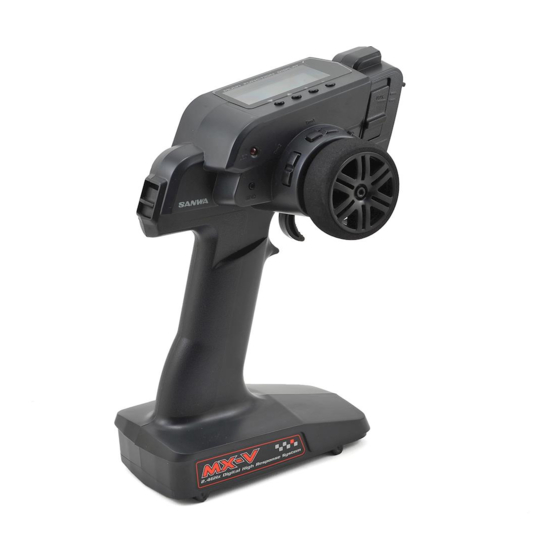
Page 6: Transmitter And Receiver Diagrams
TRANSMITTER AND RECEIVER DIAGRAMS Use the diagrams below to familiarize yourself with the different parts of your MX-V 3-Channel 2.4GHz FHSS-2 transmitter and 92625 (RX-37E) receiver. Descriptions of these parts can be found in the Transmitter and Receiver Layout Descriptions section on the next page. -
Page 7: Transmitter And Receiver Diagram Descriptions
If the Low Voltage Alarm sounds after replacing or recharging the transmitter batteries, there may be a problem with the transmitter. If this occurs, please contact Airtronics Customer Service using the information in the Service and Support section on page 3. -
Page 8: Receiver Connections And Mounting
MX - V 3 - CHANNEL 2.4GHZ RADIO SYSTEM USER'S GUIDE RECEIVER CONNECTIONS AND MOUNTING Use the diagram below to make the connections to the 92625 (RX-37E) 3-Channel 2.4GHz FHSS-2 receiver included with your MX-V 3-Channel 2.4GHz FHSS-2 radio control system. -
Page 9: Transmitter And Receiver Binding
MX - V 3 - CHANNEL 2.4GHZ RADIO SYSTEM USER'S GUIDE LCD AND PROGRAMMING KEYS Selecting menus and programming the transmitter is accomplished using the four programming keys. PROGRAMMING KEY NAME FUNCTION Cycles down through the list of menus and sub-menu functions you would like to make programming changes to. -
Page 10: Throttle Fail Safe Programming
MX - V 3 - CHANNEL 2.4GHZ RADIO SYSTEM USER'S GUIDE THROTTLE fAIL SAfE PROGRAMMING The Throttle Fail Safe function automatically moves the throttle servo to a predetermined position in the event that the signal between the transmitter and the receiver is interrupted, whether due to signal degradation or to low transmitter battery voltage. For example, the Throttle Fail Safe function can be set so that the throttle returns to idle or the brake engages so that your model doesn't run away if the signal is lost. -
Page 11: Dual Rate
MX - V 3 - CHANNEL 2.4GHZ RADIO SYSTEM USER'S GUIDE D / R - DUAL RATE The Dual Rate function allows you to change the control authority of your model's steering by changing the amount of servo travel relative to control input. For example, by increasing the Dual Rate, you can make the steering servo travel more which might prevent your model from pushing during turns. - Page 12 MX - V 3 - CHANNEL 2.4GHZ RADIO SYSTEM USER'S GUIDE EPA - END POINT ADjUSTMENT Adjusting the Steering End Point Adjustment Percentage Values: Your model’s turning radius can differ from left to right because of variations in linkage, suspension balance, tire diameter or weight distribution.
-
Page 13: Exponential
MX - V 3 - CHANNEL 2.4GHZ RADIO SYSTEM USER'S GUIDE EPA - END POINT ADjUSTMENT Adjusting the Auxiliary Channel 3 End Point Adjustment Percentage Values: Auxiliary Channel 3 can be used for a number of different uses. One of the more common uses would be for the reverse function in a glow-powered monster truck. -
Page 14: Anti-Lock Braking
MX - V 3 - CHANNEL 2.4GHZ RADIO SYSTEM USER'S GUIDE EXP - EXPONENTIAL Adjusting the Steering Exponential Percentage Value, Continued: 2) Press the INCREASE or DECREASE keys to change the Steering Exponential percentage value. Decreasing the Steering Exponential percentage value will make the steering less sensitive around Neutral and increasing the Steering Exponential percentage value will make the steering more sensitive around Neutral. -
Page 15: Servo Trim
MX - V 3 - CHANNEL 2.4GHZ RADIO SYSTEM USER'S GUIDE ALb - ANTI-LOCK bRAKING Activating the Anti-Lock Braking Function, Continued: 2) Press the INCREASE or DECREASE keys to choose the desired Anti-Lock Braking Pulse Rate value. The Pulse Rate value determines how fast the throttle servo pulsates the brake. -
Page 16: Model Select
MX - V 3 - CHANNEL 2.4GHZ RADIO SYSTEM USER'S GUIDE TRIM - SERVO TRIM Controlling the Servo Trim Function: 1) Steering and Throttle Servo Trim can be adjusted at any time while driving. Trim Switch Trm1 controls the Steering Right and Left Servo Trim and Trim Switch Trm2 controls the Throttle Forward and Brake Servo Trim. -
Page 17: Servo Reversing
MX - V 3 - CHANNEL 2.4GHZ RADIO SYSTEM USER'S GUIDE SUb-T - SERVO SUb-TRIM After adjusting the Servo Sub-Trim values, use the End Point Adjustment function to set the desired amount of maximum servo travel in both directions. For more information, see the End Point Adjustment section on pages 11 through 13. Changing the Steering Servo Sub-Trim Value: 1) Press the MENU UP or MENU DOWN keys to open the SUB-T menu. -
Page 18: Model Naming
MX - V 3 - CHANNEL 2.4GHZ RADIO SYSTEM USER'S GUIDE NAME - MODEL NAMING The Model Naming function allows you to name each of the 10 different models. This makes it easy to keep track of multiple models. The Model Name can consist of up to 3 upper-case letters, numbers or symbols, or a combination of all three. Before naming your model, use the Model Select function to choose the Model Number you would like to name. -
Page 19: Troubleshooting Guide
This troubleshooting guide can help you diagnose and solve some of the more common problems that you may encounter with your MX-V 3-Channel 2.4GHz FHSS-2 radio control system. If you cannot solve the problem using this troubleshooting guide, please contact Airtronics Customer Service using the information in the Service and Support section on page 3. CAUSE SOLUTION PRObLEM... - Page 20 MX - V 3 - CHANNEL 2.4GHZ RADIO SYSTEM USER'S GUIDE GLOSSARY Of TERMS Binding: The act of pairing the transmitter and receiver to prevent interference from transmitters operated by other users. The transmitter and receiver must be paired so that the two can 'talk' to each other. Once the binding procedure is complete, the setting is remembered even when the transmitter and receiver are turned OFF.
-
Page 21: Index
Voltage Monitor: Displays the current voltage of the transmitter batteries. When the transmitter batteries reach 4.6 volts, the Low Voltage Alarm will sound. Z-Connector: The type of servo and battery connector used by Airtronics. The Z-Connector is a universal connector which is electronically compatible with the components of other radio control system manufacturers. - Page 22 MX - V 3 - CHANNEL 2.4GHZ RADIO SYSTEM USER'S GUIDE INDEX High Side, Definition of 20 Receiver Fail Safe. See Throttle Fail Safe, Programming Receiver Precautions 4 Receiver Specifications 5 Receiver, Using 7.4 Volt Servos 8 Increase Key. See Programming Keys, Overview RF Exposure Statement 3 Increase Key, Definition of 20 Input Voltage.
-
Page 23: Notes
MX - V 3 - CHANNEL 2.4GHZ RADIO SYSTEM USER'S GUIDE NOTES... - Page 24 MX - V 3 - CHANNEL 2.4GHZ RADIO SYSTEM USER'S GUIDE Airtronics is Distributed Exclusively in North America by: Global Hobby Distributors 18480 Bandilier Circle Fountain Valley, CA 92708 Telephone: (714) 963-0329 Fax: (714) 964-6236 Email: service@airtronics.net http://globalservices.globalhobby.com http://www.airtronics.net Features and Specifications are Subject to Change Without Notice.
Need help?
Do you have a question about the MX-V and is the answer not in the manual?
Questions and answers