Table of Contents
Advertisement
Advertisement
Table of Contents

Related Manuals for AIRTRONICS MX-Sport


Summary of Contents for AIRTRONICS MX-Sport
- Page 1 Page 1...
-
Page 2: Table Of Contents
Please read this Operating Manual carefully so that you may obtain maximum success and enjoyment from the operation of your new radio control system. The MX-Sport 2.4GHz FHSS-2 radio control system has been designed for the utmost in comfort and precise control of all types of model cars and boats. We wish you the best of success and fun with your new purchase. -
Page 3: Usage.precautions
FCC authorization to operate this equipment. RF Exposure Statement This transmitter has been tested and meets the FCC RF exposure guidelines when used with the Airtronics accessories supplied or designated for this product, and provided at least 20cm separation between the antenna and the user's body is maintained. -
Page 4: Transmitter.precautions
uSAgE PrECAuTiONS 2.4gHz FrEquENCy BANd PrECAuTiONS, CONTiNuEd..If the 2.4GHz frequency band is saturated (too many transmitters on at once), as a safety precaution, the radio control system may not bind. This ensures that your radio control system does not get hit by interference. Once the frequencies have been cleared, or the saturation level has dropped, your radio control system should be able to bind without any problems. -
Page 5: Features.and.specifications
Unlike ordinary crystal-based systems, your model can be used without frequency control. OPTiONAL iTEmS The following optional items (available separately) can be used with your MX-Sport 2.4GHz FHSS-2 radio control system. For pricing and availability, please visit your local Airtronics dealer or our website at http://www.airtronics.net. 233884... -
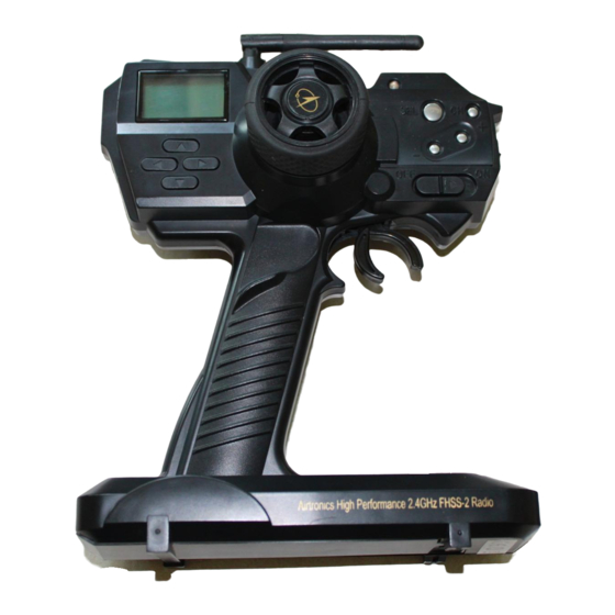
Page 6: Features.familiarization
FEATurES FAmiLiArizATiON TrANSmiTTEr ANd rECEivEr FEATurES diAgrAmS Use the diagram below to familiarize yourself with the different features of your MX-Sport transmitter. Descriptions of these features can be found on the next page. Auxiliary Channel 3 is NOT a proportional channel. -
Page 7: Features.descriptions
Throttle Trim Switch: Used to adjust the center Trim of the Throttle servo. SErvO CONNECTOrS The 92524 3-Channel receiver included with your MX-Sport 2.4GHz FHSS-2 radio control system uses universal Airtronics 'Z' connectors which are electronically compatible with the servos of other radio control system manufacturers. -
Page 8: System.connections
SySTEm CONNECTiONS TrANSmiTTEr BATTEry iNSTALLATiON 1) Remove the battery cover on the bottom of the transmitter by pushing firmly on the battery cover in the direction of the arrow. 2) Install eight fresh 'AA' Alkaline batteries into the battery tray, making sure that the polarity is correct. The direction that each battery should be installed is molded into the battery tray (+ Positive and - Negative). -
Page 9: Transmitter.and.receiver.battery.options
Charging the Optional Ni-MH Transmitter and Receiver Batteries The MX-Sport transmitter features a Charging Jack located on the left side of the transmitter, allowing you to recharge the optional rechargeable batteries without removing them from the transmitter. Use ONLY the recommended optional Airtronics 95033Z 110v AC Transmitter and Receiver dual charger or damage to the transmitter and/or batteries could result. -
Page 10: Lcd.and.programming.keys
LCd ANd PrOgrAmmiNg kEyS The MX-Sport transmitter features four Programming Keys that are used to facilitate transmitter programming. four Programming Keys consist of the SEL (Menu Select) key, the CH (Channel Select) key, the + (Increase) key, and the - (Decrease) key. This section summarizes the functions of each of the four Programming Keys, in addition to describing the main areas of the Multi-Function LCD. -
Page 11: System.setup
SySTEm SETuP TrANSmiTTEr ANd rECEivEr BiNdiNg The Binding function allows you to Bind the transmitter and receiver pair. When new, it is necessary to pair the transmitter and receiver to prevent interference from radio controllers operated by other users. This operation is referred to as 'binding'. -
Page 12: Programming.and.system.use
PrOgrAmmiNg ANd SySTEm uSE When the transmitter is turned ON, the Voltage Indicator will be displayed. To cycle through the different Programming Menus, press the SEL key. The currently selected Programming Menu will be displayed. When you make Programming Value changes, those changes are reflected immediately. There is no need to 'save' your changes. If you're in a Programming Menu when you turn the transmitter OFF, the Voltage Indicator will be displayed when the transmitter is turned back ON. - Page 13 PrOgrAmmiNg ANd SySTEm uSE rEv - SErvO rEvErSiNg The Servo Reversing function allows you to electronically switch the direction of servo travel. For example, if you move the steering wheel to the right, and the steering servo moves to the left, you can use the Servo Reversing function to make the steering servo move to the left.
-
Page 14: Epa.-.End.point.adjustment
PrOgrAmmiNg ANd SySTEm uSE EPA - ENd POiNT AdjuSTmENT The End Point Adjustment function is used to adjust the amount of servo travel in both directions independently. This makes it possible to balance servo travel in both directions. End Points can be adjusted for the Steering channel (Right and Left) and the Throttle channel (Throttle High and Throttle Brake). -
Page 15: Exp.-.Exponential
PrOgrAmmiNg ANd SySTEm uSE Adjusting Throttle End Point Adjustment, Continued..If you're using an electronic speed control, the Throttle High and the Throttle Brake End Point Adjustment percentage values are both generally set to 100%, although the Throttle High direction may need to be increased to achieve full power. -
Page 16: Abs.-.Anti-Lock.braking
PrOgrAmmiNg ANd SySTEm uSE Adjusting Throttle Exponential Throttle Exponential can be variably adjusted from Mild through Linear to Quick. In general, reduce the Exponential percentage value on a slippery track or with a model that has a higher-torque motor or engine. Increase the Exponential percentage value on a high-grip track or with a model that has a lower-torque motor or engine. -
Page 17: Name.-.Model.naming
Trim mEmOry The MX-Sport transmitter features Digital Trim Memory. Any amount of Steering or Throttle Trim that you set during use by pressing the Trim switches is automatically stored in memory for that specific channel and for that specific Model Number. -
Page 18: Dual.rate
PrOgrAmmiNg ANd SySTEm uSE Setting Up Your Model's Control Linkages, Continued..2) Install the servo horns onto the servos, making sure that the servo horns are as close to being centered as possible. In some cases, you can get the servo horns closer to being centered by rotating the servo horns 180º... -
Page 19: Low.voltage.alarm
PrOgrAmmiNg ANd SySTEm uSE Adjusting Throttle Dual Rate It is not too common to use Dual Rate on the throttle. In most cases the Throttle Dual Rate percentage value is left at 100%. Be aware that if you decrease the Throttle Dual Rate percentage value, you may not achieve full power or braking. -
Page 20: Troubleshooting.guide
TrOuBLESHOOTiNg guidE This troubleshooting guide has been provided to help you diagnose and solve most problems that you may encounter with your MX-Sport 2.4GHz FHSS-2 radio control system. Most problems encountered can be solved by following the problem-cause-solution sections. If you cannot solve the problem using this troubleshooting guide, please contact us using the information on the back cover of this Operating Manual. -
Page 21: Glossary.of.terms
rEFErENCE gLOSSAry OF TErmS Antenna: Transmits the signal from the transmitter to the receiver in the model. Antenna Wire: The antenna wire receives the transmitter signal. The antenna wire should be installed through a nylon tube (antenna tube) in the vertical position for the best reception. Anti-Lock Braking: A function that makes it possible to achieve stable braking even on a slippery track. -
Page 22: Index
8.5 volts, LOW will be displayed and an audible alarm will sound. Z-Connector: The type of servo and battery connector used by Airtronics. The Z-Connector is a universal connector which is electronically compatible with the airborne components of other radio control system manufacturers. - Page 23 rEFErENCE iNdEx, CONTiNuEd..Menu Select Key. See.also Programming Keys, Overview Safety 3 Menu Select Key, Definition of 7 SEL Key. See Menu Select Key Menu Select Key, Diagram of 6 Servo Connectors, Overview 7 Model Naming, Naming Your Model 17 Servo Recommendations 9 Model Number, Overview 10 Servo Reversing, Programming 13...
- Page 24 Airtronics is Distributed Exclusively in North America by: Global Hobby Distributors 18480 Bandilier Circle Fountain Valley, CA 92708 Telephone: (714) 963-0329 Fax: (714) 964-6236 Email: service@airtronics.net http://globalservices.globalhobby.com http://www.airtronics.net Features and Specifications are Subject to Change Without Notice. All contents © 2010 Airtronics, Inc.
Need help?
Do you have a question about the MX-Sport and is the answer not in the manual?
Questions and answers