Table of Contents
Advertisement
Advertisement
Table of Contents

Related Manuals for AIRTRONICS SD-5G


Summary of Contents for AIRTRONICS SD-5G
- Page 1 Page 1...
-
Page 2: Table Of Contents
Service Information ..............................Back Cover Packaging The packaging of your Airtronics SD-5G 2.4GHz FHSS-1 radio control system has been specially designed for the safe transportation and storage of the radio control system's components. After unpacking your radio control system, do not discard the packaging materials. -
Page 3: Introduction
Please read this Operating Manual carefully so that you may obtain maximum success and enjoyment from the operation of your new SD-5G 2.4GHz FHSS-1 radio control system. This radio control system has been designed for the utmost in comfort and precise control of your aircraft models. -
Page 4: Safety And Usage Precautions
SaFETy anD USagE PREcaUTiOnS In addition to the FCC Compliance section on the previous page, please observe the following Safety and Usage Precautions when installing and using your Airtronics SD-5G 2.4GHz FHSS-1 radio control system. gEnERaL SaFETy Be certain to read this Operating Manual in its entirety. -
Page 5: Receiver Precautions
Reception can be blocked if the antenna reception wires are shielded inside a carbon fiber fuselage. The manufacturer disclaims all responsibility for damages resulting from use of components other than genuine Airtronics components. -
Page 6: Features And Specifications
Weight: 1.62oz (45.8gr) Weight: 2.04oz (58.0gr) Weight: 2.36oz (67gr) Both analog and digital servos will work with your SD-5G 2.4GHz FHSS-1 radio control system. To get the most out of your experience though, we recommend the use of digital servos. Page 6... -
Page 7: Features Familiarization
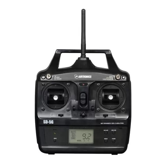
FEaTURES FaMiLiaRizaTiOn TRanSMiTTER FEaTURES DiagRaM Use the diagram below to familiarize yourself with the different features of your SD-5G 2.4GHz FHSS-1 transmitter. Descriptions of these features can be found on pages 8 and 9. The transmitter antenna is adjustable. It should be adjusted so that when you're holding the transmitter while you're flying, the antenna is orientated as close to perpendicular to the ground as possible at all times. -
Page 8: Receiver Features Diagram
Throttle/ESC Channel Slot 6*/BATT Flaps*/Battery *When used with the SD-5G transmitter, this channel slot is used for receiver battery power only. No other channel function is associated with it. FEaTURES DEScRiPTiOnS Aileron/Elevator Control Stick: Controls the Aileron and Elevator axes. The Aileron/Elevator control stick length is adjustable to suit your preference. -
Page 9: Servo Connections
LOw vOLTagE aLaRM The SD-5G transmitter is equipped with a Low Voltage Alarm that will sound when the transmitter batteries reach 6.7 volts. If the Low Voltage Alarm sounds while you are flying, you should land immediately, then replace or recharge the transmitter batteries. -
Page 10: System Connections
SySTEM cOnnEcTiOnS TRanSMiTTER BaTTERy inSTaLLaTiOn 1) Remove the battery cover on the back of the transmitter by pushing down firmly on the tab in the top of the battery cover and pulling the battery cover out. 2) Install six fresh 'AA' Alkaline batteries into the battery tray, making sure that the polarity is correct. The direction that each battery should be installed is molded into the battery tray (+ Positive and - Negative). -
Page 11: Transmitter And Receiver Battery Options
Charging the Optional Ni-MH Transmitter and Receiver Batteries The SD-5G transmitter features a Charging Jack located on the right side of the transmitter, allowing you to recharge the optional rechargeable batteries without removing them from the transmitter. Use ONLY the recommended optional Airtronics 95034 110v AC Transmitter and Receiver dual charger or damage to the transmitter and/or batteries could result. -
Page 12: Lcd And Programming Keys
LcD anD PROgRaMMing kEyS The SD-5G 2.4GHz FHSS-1 transmitter features four Programming Keys that are used to facilitate transmitter programming. The four Programming Keys consist of the INC+/M1 (Increase/Model 1) key, the DEC-/M2 (Decrease/Model 2) key, the CH/M3 (Channel Select/Model 3) key, and the MENU key. This section summarizes the functions of each of the four Programming Keys, in addition to describing the main areas of the Multi-Function LCD. -
Page 13: System Setup Installation
SySTEM SETUP anD inSTaLLaTiOn TRanSMiTTER anD REcEivER BinDing The Binding function allows you to Bind the transmitter and receiver pair. When new, it is necessary to pair the transmitter and receiver to prevent interference from radio controllers operated by other users. This operation is referred to as 'binding'. Once the binding process is complete, the setting is remembered even when the transmitter and receiver are turned OFF. -
Page 14: Mounting The Receiver
SySTEM SETUP anD inSTaLLaTiOn MOUnTing ThE REcEivER When mounting the receiver into your model, it's important to mount the receiver exactly as described. In addition, the receiver should be wrapped in foam rubber to protect it from vibration. Failure to mount the receiver antenna wires as described can result in poor reception, or in some cases, complete loss of reception. -
Page 15: Range Checking - Low-Power Mode
If, after checking all airborne system components and verifying correct antenna wire mounting, your radio control system still fails the Range Check, DO NOT FLY. Please contact Airtronics Customer Service using the information on the back cover of this Operating Manual. -
Page 16: Programming
For rainer unCtion *The Trainer menu option is only displayed when a trainer cable is plugged into the DIN Connector on the back of the SD-5G transmitter. For more information, see pages 19 and 20. BaTT - BaTTERy The Battery function displays the current voltage of the transmitter batteries. When the transmitter is turned ON, BATT will flash and the Digital Voltage Indicator will be displayed in the Programming Window. -
Page 17: Epa - End Point Adjustment
PROgRaMMing EPa - EnD POinT aDjUSTMEnT The End Point Adjustment function allows you to adjust servo travel in both directions equally. This makes it possible to quickly and easily adjust maximum control surface deflection without the need to physically adjust the control linkages. For example, if you want your elevator to move Up and Down 1", but the elevator moves Up and Down more than 1", you can decrease the End Point Adjustment percentage value to make the elevator move Up and Down 1". -
Page 18: Rev - Servo Reversing
PROgRaMMing Changing End Point Adjustment Percentage Values - Throttle Channel, Continued..2) To set the Throttle Low End Point Adjustment percentage value, pull the throttle control stick all the way back. TH L 100% will be displayed in the Programming Window. Press the INC+/M1 or DEC-/M2 keys to increase or decrease the amount of throttle servo travel in the Throttle Low direction. -
Page 19: Wing - Channel Mixing
TRainER - TRainER SySTEM The SD-5G transmitter features a Trainer System that allows you to connect two SD-5G transmitters or one SD-5G transmitter and one SD-10G transmitter for the purpose of training a new pilot or for training a more experienced pilot on a new model. - Page 20 1) Turn both transmitters OFF. 2) Plug one end of the Airtronics 97107 Trainer Cable (available separately) into the back of one SD-5G transmitter, then plug the other end of the Trainer Cable into the second SD-5G transmitter or an SD-10G transmitter.
-
Page 21: Control Functions
DiREcT MODEL SELEcT The SD-5G transmitter can store Programming Data for up to 3 different models - Model 1, Model 2, and Model 3. The Direct Model Select function allows you to select which of the three models you would like to use. -
Page 22: Dual Rate
cOnTROL FUncTiOnS Using the Trim Switches, Continued..2) Press the trim switches up or down, or right or left, to change the center trim of the servos. The current amount of Trim for that particular channel is displayed in the Programming Window. TRM setting range is -100 to 100. -
Page 23: Troubleshooting Guide
SD-5G 2.4GHz FHSS-1 radio control system. Most problems encountered can be solved by following the problem-cause-solution sections. If you cannot solve the problem using this troubleshooting guide, please contact Airtronics Customer Service using the information on the back cover of this Operating Manual. - Page 24 Bind LED: Displays the current status of the transmitter and receiver pair. Charging Jack: Used for onboard charging of the optional Ni-Cd or Ni-MH batteries. An optional Airtronics 95034 110v AC Transmitter and Receiver dual charger is available separately.
-
Page 25: Glossary
Z-Connector: The type of servo and battery connector used by Airtronics. The Z-Connector is a universal connector which is electronically compatible with the airborne components of other radio control system manufacturers. -
Page 26: Index
inDEx Symbols 2.4GHz Frequency Band, Precautions 4 Aileron Trim Switch, Diagram of 7 Airborne System Connections, Overview 9 Alarm. See also Low Voltage Alarm Antenna Reception Wires, Receiver - Definition of 8, 24 Antenna Reception Wires, Receiver - Diagram of 8 Antenna Reception Wires, Receiver - Mounting 14 Antenna, Transmitter - Definition of 8, 24 Antenna, Transmitter - Diagram of 7... - Page 27 inDEx Multi-Function LCD. See also LCD Multi-Function LCD, Definition of 9, 24 Neck Strap Anchor, Definition of 9, 25 Neck Strap Anchor, Diagram of 7 Operating Voltage, Definition of 25 Operating Voltage, Receiver. See also Input Voltage, Receiver Operating Voltage, Transmitter 6 Output Power, Transmitter 6 Packaging 2 Percentage Icon, Diagram of 12...
- Page 28 Airtronics is Distributed Exclusively in North America by: Global Hobby Distributors 18480 Bandilier Circle Fountain Valley, CA 92708 Telephone: (714) 963-0329 Fax: (714) 964-6236 Email: service@airtronics.net http://globalservices.globalhobby.com http://www.airtronics.net Features and Specifications are Subject to Change Without Notice. All contents © 2010 Airtronics, Inc.
Need help?
Do you have a question about the SD-5G and is the answer not in the manual?
Questions and answers