Table of Contents
Advertisement
Quick Links
Advertisement
Table of Contents

Summary of Contents for SAKI BF-Sirius
- Page 1 BF-Sirius Manual [ SJ241DCM1-02E ]...
- Page 2 “WARNING” indicates a potentially hazardous situation which could be threat to life or cause WARNING serious injury. “CAUTION” indicates a potentially hazardous situation which could result in injury or equipment CAUTION (including peripheral) damage. NOTE “NOTE” indicates an advice on operation. Document Disclaimer • For easier understanding, some of the figures and photographs included in this manual may be slightly different from the actual objects depicted. • For improvement and enhancement purposes, the physical appearance and specifications for the product are subject to change without notice. • All brand names and product names contained in this manual are trademarks or registered trademarks of their respective companies. • Saki Corporation has copyright of all the contents in this manual. No part of this manual may be reproduced into any form without prior written consent of Saki Corporation, and be used for improper purposes of the Manual. Copyright©2011 Saki Corporation. All Rights Reserved. Printed in Japan. Saki Corporation BF-Sirius Manual (Original Instructions) BF-Sirius...
- Page 3 This symbol indicates the presence of a rotating or spinning object which could damage things. This symbol indicates the potential danger of electric shock. WARNING To avoid electric shock or fire, and to ensure safety, do not disassemble, repair, or modify the machine. The equipment should not be installed in a place subject to fumes, steam, high humidity, or dust particles. Using the system in an environment in violation of the operating conditions described in the Manual can cause fire or electric shock. To avoid damage to the cable, the following actions should never be performed: bending the cord by force, pulling the cord, or placing it near heating equipment. To avoid electric shock or fire, damaged power supply cords, or loose outlets should not be used. To avoid electric shock or fire, the voltages higher or lower than the indicated power supply voltage should not be used. To avoid electric shock or fire, power supply cords other than those designated should not be used. To avoid system malfunction or unexpected accidents, the mounted cover should never be opened. Do not cover up the inlet of this machine. And do not insert a foreign substance. If the inlet is covered up, an inside will be filled with heat and it could cause fire or failure. Insert power supply cord in outlet firmly. When water, a foreign substance etc goes into the inside, first of all, shut off the power supply, and extract the power supply cord and connection cable of the main machine. Please contact Saki Corporation or our representatives. When discarding the this machine, comply with local regulations. BF-Sirius...
- Page 4 ・To avoid burns or injury, let the electric components and units cool down sufficiently. Do not put a hand or any object in the driven section during the machine running. It may result in personal injury. To avoid malfunction or accidents, do not touch any system internal structure with the exception of components described in this manual. Connect the ground lead (to prevent electric shock in the event of current leakage) of the power plug to one of the following items. ・Ground terminal of power outlet ・Installed (Type A - D) ground terminal ・Pipe permitted as the grounded object by waterworks department With the power supply turned on, please do not move the main machine. It may result in electric shock or personal injury. To avoid electric shock, do not touch the power supply cord with a wet hand. Front View Rear View Injury can result if fingers or hands are caught between the scan table and base or between the motor and ball screw. WARNING Although area sensor is operated as assist device for safety, do not touch the unit when the machine is running. Be sure to turn off the earth leakage breaker before servicing the unit. Voltage hazard. Risk of electric shock. WARNING Unplug the power supply cord before opening the cover. BF-Sirius...
-
Page 5: Table Of Contents
3.5.2 PCB Loading / Unloading Method ........I-17 3.6 Window Details ................I-18 3.7 Operation Flow ................I-19 3.8 Manual Mode ................I-20 3.8.1 Operation Procedure of Manual Mode ......I-20 3.8.2 Inspection Method of Manual Mode ........I-20 3.9 Auto Mode .................I-21 3.9.1 Operation Procedure of Auto Mode ........I-21 3.9.2 Inspection Method of Auto Mode ........I-21 3.9.3 False Call Detection ............I-24 3.10 Basic Functional Items .............I-27 BF-Sirius... - Page 6 Maintenance and Service .........IV-4 Table of Contents 2.1 Maintenance and Service ............IV-4 2.1.1 After Sales Service ............IV-4 2.1.2 Product Warranty ............. IV-4 2.1.3 Maintenance Check Service ..........IV-5 2.1.4 Others ................IV-5 2.2 Customer Support Contacts ............ IV-5 Information on Terms of Use ........IV-6 EC Declaration of Conformity ........IV-8 BF-Sirius...
- Page 7 Operation Manual Operation Manual BF-Sirius...
-
Page 8: Product Overview And Features
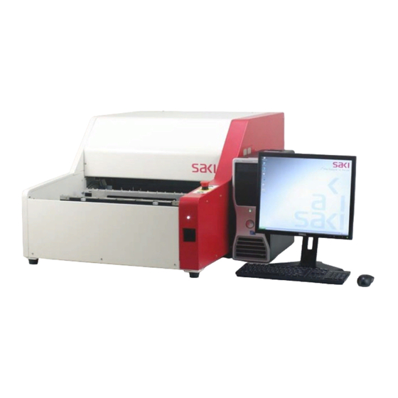
Operation Manual 1 Product Overview and Features 1.1 Product Overview This product is Benchtop high-speed Automated Optical Inspection system that acquire detail image of a PCB in one pass by using a line scan sensor camera and store all information embedded in the images in a computer memory to conduct high speed inspection and judgement by employing Saki original image processing technology. BF-Sirius can be used in any stage of PCB manufacturing process from manual mounting to automated post-print, post-mount, as well as post-flow / reflow inspections. 1.2 Features 1.2.1 System Structure • This is compact and easy to use Benchtop High Speed Automated Optical Inspection system. The machine equipped with newly developed CCD camera and illumination lighting to realize high throughput for scan of L size board (460 (W) × 500 (L) mm) within approximately 10 seconds. •... -
Page 9: Product Configuration
A outlet to supply power for LCD monitor. LU01 Power Lamp Turn on the machine and the lamp lights on. SW01 Main Breaker Breaker which regulates the power supply. POWER stand for main breaker. Used in Auto Mode. Push this switch after unloading / loading PCB and start SW02 Start Switch scanning and inspection. START stand for start switch. When the machine needs emergency stop, push this switch to stop inspection at SW03 Emergency Stop Switch once. Enable the scan table to move manually. EMERGENCY STOP stand for emergency stop switch. SW04 Reset Switch Release the emergency stop status. RESET stand for reset switch. PT01 Name Plate Machine specification is described. Table 2-1 Name and Function of Each Unit BF-Sirius... -
Page 10: Internal View
MC01 MR01 MC02 Internal Top Layer View Bottom Layer View FN02 MC06-02 FN01 CP03 NF01 MC06-01 Internal Rear View EC07 PS02 PS03 PB17 PB24 MD01 TB01 PS01 PS04 Internal Left Side View Internal Right Side View FFFure 2-3 Internal View BF-Sirius... - Page 11 Performs signal conversions so that images scanned by the left side CCD PB19-02 Image Processing Board 2 Unit can be transferred to the PC. [SJPB1GA00] Synchronize the image signals from Image Processing Board 1 and 2. PB20 Extension Board Transfer scan image to the PC. [SJPB1HA00] PB21-01 CCD Unit 1 Scans the inspection image of the right half. [SJPB2AA00] PB21-02 CCD Unit 2 Scans the inspection image of the left half. [SJPB2AA00] Controls DC24V power supply to the LED illumination unit and its lighting. PB23 LED Driver Board [SJPB2RC00] PB24 PLC Relay Board Relays the signals to the PLC. [SJPB2FB00] PS01 DC 12V Power Supply Convert AC power supply into DC 12V. [SJEC1P004] PS02 DC 5V Power Supply Convert AC power supply into DC 5V. [SJEC1P005] PS03 DC 5V/24V Multi Power Supply Convert AC power supply into DC 5V/24V. [SJEC1P013] PS04 DC 24V Power Supply Convert AC power supply into DC 24V. [SJEC1P014] TB01 Terminal Block Distribute AC to each DC power supply. Table 2-2 Name and Function of Each Unit BF-Sirius...
-
Page 12: Position Of Sensor Units
A sensor that detects whether a PCB is set in the correct position. SR03 Board Sensor [SJ24EH025] SR04 Scan Start Sensor When this sensor is sensed, start scaning. [SJ03PE014] When this sensor is sensed, the scan motor stops, beyond which the scan SR05 Rear Scan Limit Sensor table cannot move any further rearward. [SJ03PE014] Senses whether a hand or an object is caught in the inlet and outlet of PCB. SS01-01/02 Area Sensor 01 is transmitter. 02 is receiver. [SJ24EH027] Senses whether a hand or an object is caught in the inlet and outlet of PCB. SS02-01/02 Fiberoptic Sensor 01 is transmitter. 02 is receiver. [SJSS5K001] SA01 Fiberoptic Sensor Amplifier Controls the fiberoptic sensor. [SJ24EH060] Table 2-3 Name and Function of Each Sensor BF-Sirius... -
Page 13: Operation
Reset Switch Release Emergency Stop Switch Push Top View FFFure 3-1 Reset Switch and Emergency Stop Switch Step1: When emergency stop switch is pushed, the dialog shown in Figure 3-2 appears. CAUTION Pressing either OK or Cancel will not release the emergency stop condition and display the caution dialog again. FFFure 3-2 Emergency Stop Step2: Turn the emergency stop switch clockwise (to the direction indicated by blue arrow) to release the emergency stop switch. CAUTION In this situation, beep tones still sounds and the scan table can be moved manually. BF-Sirius... -
Page 14: Area Sensor
Operation Manual Step3: Push the reset switch. Beep tones stop and the scan table can not be moved manually. Step4: The dialog shown in Figure 3-2 can be selected only after releasing the emergency stop. The scan table returns to the origin position. Cancel The scan table remains at the position where it stopped. Step5: Put PCB into the bottom correctly and resume usual image scan operation. 3.1.2 Area Sensor Area sensor watches safe operation of shading procedure and image scanning. When area sensor is sensed, beep tones sound and the motor stops immediately. The system operation is suspended. Upper Area Sensor Front Area Sensor FFFure 3-3 Area Sensor When area sensor senses and stops, the dialog shown in Figure 3-4 appears. Remove any object sensed by area sensor. The scan table returns to the origin position. Cancel The scan table remains at the position where it stopped. FFFure 3-4 Area Sensor Senses BF-Sirius... -
Page 15: System Activation
Check the following items before turn on the power. If any problem occurs, please contact Saki Corporation or our representatives. • There is no deep external scratch on the inspection machine. • There is no damage in the power supply cords and connection cables. • All power supply cords and connection cables are connected firmly and correctly. • There is no object on the scan table. • There is no object which hinders table-motion. • There is no object on the machine. • There is no foreign object inserted in the entrance of the machine. 3.2.2 Turn on the Machine Step1: Turn on the earth leakage breaker on the rear side of the machine and turn the main breaker clockwise direction to power on the machine. Step2: Beep tones sound after turn on the power and push the reset switch. As the machine activates normally, the power lamp lights on. Reset Switch Power Lamp Earth Leakage Breaker Main Breaker FFFure 3-5 Turn on the Machine BF-Sirius... -
Page 16: Turn On The Pc And Start The Inspection Software
3.2.3 Turn on the PC and Start the Inspection Software Step1: Push the main breaker on the front side of the PC. When the Operating System(hereinafter OS) is activated and login window appears on the LCD monitor, enter the following login name and password. Login Name SAKICORP Password sakicorp FFFure 3-6 Login Window Step2: When the login process is successful, the inspection software(BF1.exe) for the system is automatically activated. If it fails to start automatically, double-click BF-Sirius shortcut icon on the desktop NOTE to start the inspection software. FFFure 3-7 BF-Sirius Shortcut Icon Step3: The dialog shown in Figure 3-8 appears. If the power of the machine is already on, press OK. If not, first turn on the machine without pressing Cancel and press OK. FFFure 3-8 Confirm the Power of the Inspection Machine BF-Sirius I-10... -
Page 17: Check Before Start Inspection
Operation Manual Step4: The dialog shown in Figure 3-9 appears. Press OK to return the scan table to the origin position. FFFure 3-9 Returning to the Origin 3.2.4 Check before Start Inspection Before starting inspection, check the followings. If any problem occurs, please contact Saki Corporation or our representatives. • The power lamps of the machine and the PC lights on. • There is neither smoke nor a unusual smell. • There is no abnormal noise at the time of system activation. • The inspection software starts normally. BF-Sirius I-11... -
Page 18: System Shutdown
File > Quit from the menu-bar. The same operation can also be performed by pressing Ctrl CAUTION In auto mode, press Stop from the menu-bar to return to the manual mode. FFFure 3-10 QuFt Step2: The dialog shown in Figure 3-11 appears. Press if you backup the data in E: drive. Cancel Press if you do not prefer to backup the data in E: drive. FFFure 3-11 Backup Confirmation Step3: The dialog shown in Figure 3-12 appears. For default setting, save the inspection data into D:\BF1\BF1DATA. To save another destination, check Change destination to save inspection data and specify the directory to save. NOTE Recommend to save the inspection data either make the new data or modify the data. FFFure 3-12 Save Inspection Data BF-Sirius I-12... - Page 19 Operation Manual Two kinds of the dialog as following appears according to the situation. (i) Save the inspection data file for new PCB name or group name Makes an inspection data file in the predefined position and go to Step4. Cancel Returns to the original inspection window without saving the data. FFFure 3-13 Make New Data Files Confirmation (ii) Save the inspection data file of the same PCB name or the group name by overwriting the exist data. Saves the data by overwriting basis and go to Step4. Cancel Returns to the original inspection window without saving the data. FFFure 3-14 Overwrite Saving Confirmation Step4: After confirmed saving inspection data, the dialog shown in Figure 3-15 appears. Quit the inspection software(BF1.exe). Cancel Return to the original inspection window. FFFure 3-15 Quit the Inspection Software BF-Sirius I-13...
-
Page 20: Check At Closing Of Work
FFFure 3-17 Turn Off Step7: Make sure the OS is shutted down and turn the main breaker counter-clockwise direction to power off the machine(refer to Figure 3-5 Turn on the Machine). CAUTION Since the PC capacitor charged electricity after shutting down the PC, wait for about one minute before restarting the PC. 3.3.2 Check at Closing of Work After system shutdown, check the following items for the next inspection. When any problem occurs, please contact Saki Corporation or our representatives. • The power lamps of the machine and the PC lights off. • There is neither smoke nor a unusual smell. • There is no damage on the inspection machine. • There is no damage in the power supply cords and connection cables. • There is no object on the scan table. • There is no object on the machine. 3.3.3 Long Term System Shutdown The machine will not be used for a long time, turn off the main breaker and the earth leakage breaker. Unplugged the power supply cord. BF-Sirius I-14... -
Page 21: Select Inspection Data
3.4 Select Inspection Data Step1: Press Select Data button on the tool-bar or select File > Select Data from the menu-bar. FFFure 3-18 Select Data Step2: The dialog shown in Figure 3-19 appears. Press if you backup the data in E: drive. Cancel Press if you do not prefer to backup the data in E: drive. FFFure 3-19 Backup Confirmation Step3: The dialog shown in Figure 3-20 appears. For default setting, save the inspection data into D:\BF1\BF1DATA. To save another destination, check Change destination to save inspection data and specify the directory to save. Recommend to save the inspection data either make the new data or modify the data. NOTE FFFure 3-20 Save Inspection Data BF-Sirius I-15... - Page 22 Operation Manual Two kinds of the dialog as following appears according to the situation. (i) Save the inspection data file for new PCB name or group name Makes an inspection data file in the predefined position and go to Step4. Cancel Returns to the original inspection window without saving the data. FFFure 3-21 Make New Data Files Confirmation (ii) Save the inspection data file of the same PCB name or the group name by overwriting the exist data. Saves the data by overwriting basis and go to Step4. Cancel Returns to the original inspection window without saving the data. FFFure 3-22 Overwrite Saving Confirmation Step4: The dialog shown in Figure 3-23 appears. Select inspection data and press For default setting, save the inspection data in D:\BF1\BF1DATA. NOTE FFFure 3-23 Select Inspection Data BF-Sirius I-16...
-
Page 23: Loading / Unloading A Pcb
3.5 Loading / Unloading a PCB 3.5.1 Guide Width Adjustment Method The below operation needs to be done when you inspect the different size of PCBs. Step1: Loosen the clamp lever. Clamp Lever Sub Backup Pin FFFure 3-24 Clamp Lever Step2: Put the PCB close against front side of the guide rail. Step3: Adjust the rail width and fix the clamp lever. CAUTION When you inspect large PCB, support PCB using sub backup pin. Sub backup pin set position without components. 3.5.2 PCB Loading / Unloading Method Put the PCB close against front side of the guide rail and carefully put the other side of the PCB on the back side of the guide rail. Position the PCB leaning the PCB to the stopper on the right side and also to the guide rail to the front side. BF-Sirius I-17... -
Page 24: Window Details
FFFure 3-25 Window Names Operation Mode Inspection Data Inspection Result Index Display Component Data All Inspection Results Position Coordinate FFFure 3-26 Explanation of Index Frame Index Display can be selected from the following formats. Select View > Results from the NOTE menu-bar. Display the corresponding components in Component Data. Worst 20 Rank the components in which defects are found by the number of occurrences, and display the worst 20 components. False 20 Rank the components in which false defects are found by the number of false defect occurrences, and displays the worst 20 components. Display the components that produced NG inspection results. Display the components that produced OK inspection results. BF-Sirius I-18... -
Page 25: Operation Flow
Scan Scan Unload PCB Inspect Inspect Edit Data Advanced System Setting Advanced System Setting Edit Data Edit Data System End System End FFFure 3-27 Diagram of the System Basic Behaviors The operations all first start with selecting each mode based on Manual Mode(refer to Figure 3-27 Diagram of the System Basic Behaviors). Manual Mode and Auto Mode can be switched by pressing Auto or Stop from the menu-bar. User can select an inspection data and configure the detail setting of the various system in Manual Mode. Also editing an inspection data is basically done in Manual Mode. Depending on the setting, user can edit an inspection data in either Auto Mode. All the setting files will have to be saved manually on the system. BF-Sirius I-19... -
Page 26: Manual Mode
Press Scan button on the tool-bar or select Scan from the menu-bar. Inspection Press Inspect button on the tool-bar or select Inspect from the menu-bar. ↓ Result output Unloading the PCB Unload the PCB manually. Table 3-1 Operation Procedure in Manual Mode 3.8.2 Inspection Method of Manual Mode Step1: Select a data according to 3.4 Select Inspection Data. Step2: Put a PCB to inspect on the scan table. Step3: Press Scan button on the tool-bar or select Scan from the menu-bar. Step4: After the PCB image is displayed on the window, check the image display for distortion or tilt. If the image is distorted or tilted, please contact Saki Corporation. Step5: Press Inspect button on the tool-bar or select Inspect from the menu-bar. Step6: Inspection result is displayed in the upper side of the index flame. If the inspection result is OK, OK is displayed in green. If defect is detected, NG is displayed in red. Step7: Unload the PCB in the machine. BF-Sirius I-20... -
Page 27: Auto Mode
Process Auto Mode Step Loading the PCB Load the PCB manually. Scanning Press Scan button on the tool-bar or select Scan from the menu-bar. Inspection Auto running. Result output ↓ Unloading the PCB Unload the PCB manually. Check the OK / NG Judge the result by OK or NG. judgement Repeat from Step 1 to Step 6. Table 3-2 Operation Procedure in Auto Mode 3.9.2 Inspection Method of Auto Mode Step1: Press Auto button on the tool-bar or select Auto from the menu-bar. The dialog shown in Figure 3-30 appears. FFFure 3-30 Auto Mode Setup Step2: Set necessary settings for automatic operation. Check Inspect. Step3: After all the settings are completed, press BF-Sirius I-21... - Page 28 Operation Manual Step4: The dialog shown in Figure 3-31 appears. Press FFFure 3-31 Starting Auto Inspection Step5: The dialog shown in Figure 3-32 appears. If OK is pressed, the scan table returns to the origin position and Waiting for Start dialog appears. FFFure 3-32 Return to the Origin BF-Sirius I-22...
- Page 29 If optional journal printer is connected to AOI and this box is checked, the NG printer information can be printed onto the roll paper. (*3) Table 3-3 Explanation on Each Item for Auto Mode Setup (*1) This does not include the numbers of the PCB inspected in Manual Mode. NOTE (*2) If you wish to continue the setup in limit count after auto running is stoppled, press Clear the Amount Fn Auto Mode Setup dialog to reset Current Board Num., and reload the image. (*3) Check the Print Barcode of Time Information, inspection time / date will be printed together with NG information. BF-Sirius I-23...
-
Page 30: False Call Detection
Operation Manual 3.9.3 False Call Detection Step1: Start Auto Mode according to 3.9.2 Inspection Method in Auto Mode. Confirm the display which shows Waiting for Start and push the start switch. Image is scanned and inspected automatically. If any components are detected, the dialog shown in Figure 3-35 appears. FFFure 3-35 Input Repair Person's Name Step2: Input Repair Person's Name dialog, either type in the name of the operator or select one from the list. Goes to the Step3. Delete Deletes the selected name from the list. NOTE Input Repair Person’s Name dialog will not be re-displayed if it is set once. BF-Sirius I-24... - Page 31 Operation Manual Step3: If inspection result is OK, the dialog shown in Figure 3-36 appears. Press OK and unload / load the PCB. Push the start switch to start the next inspection. FFFure 3-36 In Case that Inspection Result is OK If inspection result is NG, the dialog shown in Figure 3-37 appears. Each item is described in Table 3-4 and 3-5. It enables to start scanning next PCB while judging the result. NOTE FFFure 3-37 Edit NG Component Data (A) Upper Right Image Show the point that the result will be NG. (B) Upper Left Image Show the position of upper right image using yellow lines. By comparing these two images, (A) and (B) with the actual PCB, determine a good PCB vs. a defective PCB, and whether the defect is a false or not. Press if the PCB that result will be OK. REPAIR Press if the PCB that result will be NG. BF-Sirius I-25...
- Page 32 Moves to the previous or next defective spot. NG Component Designates NG to all the inspection items of the same component at once. OK Component Designates OK to all the inspection items of the same component at once. Displays the image of the first window in library registration on the upper Show Pattern right of the Defective window. Displays all windows for that component not only the window for All Windows defective spot on the upper right window. Window Displays only the defective spot windows. Drop down list under Window Allows user to change the defect type. QuFt Close Edit NG Component Data dialog. Table 3-5 Explanation of the Area D Items Step4: After all the judgements are finished, the dialog shown in Figure 3-38 appears. Press Edit NG Component Data dialog closes and the next judgement is available. FFFure 3-38 Inspect If the next PCB image was already scanned during the judgement and the result of the NOTE PCB was NG, Edit NG Component Data dialog for the next PCB appears after pressing BF-Sirius I-26...
-
Page 33: Basic Functional Items
Transfers Images to Sends data to BF-Editor. (*1) Off-line Teacher Opens Images Calls up the saved image. Select Image Saves Images Saves the image in the specified folder. Saves OK Images Not available. Opens OK Images Not available. Save or delete the image that are used for inspection data Series Scan Image debugging. Terminate Offline Debug Not available. Exchange Lamp Not available. Exchange Marking Pen Not available. Exchange Shading Plate Not available. Adjust The Board Width Not available. Show Data List Not available. Log Off Logs in the inspection software again when using privilege setup. Ctrl QuFt Quit the inspection software. Table 3-6 Items under the File Menu and their Shortcut Keys (*1) BF-Editor is the optional system to make / edit inspection data on separate PC terminal. NOTE BF-Sirius I-27... - Page 34 Unlink Library Unlink library and go back to CAD data spread status. A management window with images for marking library Library Tree classification and selection. Image Library Not available. Manages the non-inspected components and the improperly Inspection Selection loaded components per destination. Input Note Changes of inspection data with data / time etc can be input. Notes View Commentary list can be viewed. ECD Option Configures the settings of the respective parameters for the ECD function. KPK Windows Auto Activate the wizard for KPK data making(only available with Deployment fare-paying software). KPK Windows Debugging Conduct debugging on KPK data. System Tools Check Camera Function Not available. System Setup Set the detail system. Table 3-7 Items under the Edit Menu and their Shortcut Keys BF-Sirius I-28...
- Page 35 Displays the side A of the PCB image. Side B Not available. Worst 20 Displays the worst 20 components data. Display the worst 20 of false components False 20 data. Displays the defective components. Results Displays the OK components. Clear NG Data Clears the NG components. Displays the component shift information XY Offset Chart statistically. CP/CPK Not available. Select Total Display Displays the production information. Ctrl Image Plane Switches between the TopLight images and the SideLight image. Jig Panel Not available. Table 3-8 Item under the View Menu and their Shortcut Keys BF-Sirius I-29...
- Page 36 Operation Manual FFFure 3-42 Other Items Description Shortcut Keys Scan Starts scanning. Inspect Inspects the scanned image and displays the inspection result. Auto Starts the automatic running. Stop Stops the runnning. VersFon Shows the version information of the software. Help Help Calls up HELP. Table 3-9 Other Items and Their Shortcut Keys BF-Sirius I-30...
- Page 37 Maintenance Manual Maintenance Manual BF-Sirius II-1...
-
Page 38: Maintenance
The power supply to the machine must be shut off in a proper procedure as follows: before proceeding maintenance, moving the machine, or not using the machine for a long term. Incorrect procedure may cause the machine malfunction or unanticipated accident. Step1: Quit the inspection software and the OS. Step2: Turn off the main breaker. Step3: Turn off the earth leakage breaker. Step4: Unplug the power supply cord. 1.2 How to Remove External Cover Step1: Loosen the four M4 cross recessed head screws(anti-drop type) and remove the top of external cover. CAUTION The removed external covers must be handled with care not to damage or distort. M4 cross recessed head screw FFFure 1-1 Remove External Cover Step2: Reassemble the parts in an opposite procedure. BF-Sirius II-2... -
Page 39: Cleaning Optical System
WARNING Regarding the cleaning optical system, if the cleaning procedure is not operated in an appropriate way, it could cause trouble such as image misalignment. If a regular maintenance is required, please contact Saki Corporation. If you require to do the maintenance on your own, we provide specialized jigs(tools) and fare-paying training. Please contact Saki Corporation for details. Maintenance Interval Items Explanation Weekly ShadFnF Sheet Wipe off any dirt gently with a dry and soft cloth or paper. (*1) Light Control Film Camera Lens Wipe off any dirt gently with a dry and soft cloth or paper. Every 6 months Telecentric Lens In case of heavy dirt, soak a dry and soft cloth or paper in ethanol or glass cleaner and wipe them out. (*2) Mirror DFffuser Table 1-1 Cleaning Method CAUTION The maintenance interval above is a standard period, however it is subject to change depending on the machine usage environment. Make sure that the power of the machine is turned off before starting. (*1) Chemicals should not be used for cleaning. (*2) Do not use other chemicals. CAUTION Cleaning the dusts of air intake and intake fan regularly. Air Intake Intake Fan FFFure 1-2 Cleaning the Air Intake and Intake Fan BF-Sirius II-3... -
Page 40: Preparations For Optical Parts Cleaning
Maintenance Manual 1.3.1 Preparations for Optical Parts Cleaning ●Necessary Tools 1. Lint-free wiper or swab 2. Ethanol or glass cleaner 3. Gloves (Wear the gloves when cleaning mirrors or handling solvent) Lint-free Wiper Swab Ethanol Gloves (Wear gloves when cleaning Glass Cleaner mirrors or handling solvent) FFFure 1-3 Necessary Tools ●Points of Cleaning 1. Wipe off in a constant direction to prevent scratching for mirror or lens. 2. Wipe off with dry wiper or swab not to leave the solvent. FFFure 1-4 Points of Cleaning BF-Sirius II-4... -
Page 41: Cleaning Diffuser
Maintenance Manual 1.3.2 Cleaning Shading Sheet Wipe off the shading sheet gently with a dry soft wiper. CAUTION Do not use chemicals. Wipe off the shading sheet not to bend it. CAUTION Change the shading sheet if it is excessively dirty or discolored. Shading Sheet FFFure 1-5 Cleaning Shading Sheet 1.3.3 Cleaning Diffuser Step1: Remove the top of external cover. Step2: Disconnect the two connectors of LED lighting unit. Connector FFFure 1-6 Disconnect Connector BF-Sirius II-5... - Page 42 Maintenance Manual Step3: Remove the two M4 cap screws and lift up the cooling fan assembly as shown in Figure 1-7. M4 Cap Screw FFFure 1-7 Lift up the Cooling Fan Assembly Step4: Remove the two M4 cap screws and detach the LED lighting unit as shown in Figure 1-8. WARNING Detaching the LED lighting unit could cause trouble such as image distortion. If a regular maintenance is required, please contact Saki Corporation. CAUTION When removing the LED lighting unit, hold both edges of the lighting unit not to touch the LEDs. M4 Cap Screw FFFure 1-8 Remove LED Lighting Unit BF-Sirius II-6...
-
Page 43: Cleaning Light Control Film
Maintenance Manual Step5: Soak a lint-free wiper in ethanol or glass cleaner to wipe off the diffuser. CAUTION Wiping diffuser with dry wiper is recommended reducing solvent leftover. Cleaning Points Cleaning Points FFFure 1-9 Cleaning Diffuser 1.3.4 Cleaning Light Control Film WARNING Regarding the cleaning optical system, if the cleaning procedure is not operated in an appropriate way, it could cause troubles such as image misalignment. If a regular maintenance is required, please contact Saki Corporation. Step1: Remove the two M3 cap screws and detach the light control film case. M3 Cap Screw Light Control Film Case FFFure 1-10 Remove Light Control Film Case BF-Sirius II-7... -
Page 44: Cleaning Telecentric Lens, Mirror, And Camera Lens
Remove the four M3 cap screws to remove the mirror cover. Use dry wiper to wipe gently both sides of half mirror. If it is excessively dirty, soak a lint-free wiper in ethanol and wipe the half mirror to the longitudinal direction. WARNING It is possible to detach the half mirror by removing the screws which secure the mirror clamper. Regarding the cleaning mirror, if the detaching and attaching mirror procedure is not operated in an appropriate way, it could cause trouble such as image misalignment. If a regular maintenance is required, please contact Saki Corporation. CAUTION Wiping half mirror with dry wiper is recommended reducing solvent leftover. Hardly scrubbing the half mirror surface may cause the mirror coating to be taken off. Mirror Clamper (No need to remove) Half Mirror (No need to remove) Mirror Cover FFFure 1-12 Remove Mirror Cover BF-Sirius II-8... - Page 45 Soak a cotton swab in ethanol or glass cleaner to wipe the telecentric lens along the chase. Telecentric Lens FFFure 1-13 Cleaning Telecentric Lens Step3: Remove the two M4 cap screws to lift up the cover, as shown in Figure 1-14. Step4: Remove the four M4 cap screws to remove the lens cover. M4 Cap Screw M4 Cap Screw Cover Lens Cover FFFure 1-14 Remove Lens Cover BF-Sirius II-9...
- Page 46 Maintenance Manual Step5: Use dry wiper to wipe total reflection mirror gently. If it is excessively dirty, soak a lint-free wiper in ethanol and wipe the mirror to the longitudinal for evaporated surface. CAUTION Wiping mirror with dry wiper is recommended reducing solvent leftover. Evaporated Surface Evaporated Half Mirror Total Reflection Surface Mirror Evaporated Surface FFFure 1-15 Cleaning Mirror Step6: Soak a lint-free wiper in ethanol or glass cleaner and wipe camera lens. CAUTION Wiping camera lens with dry wiper is recommended reducing solvent leftover. Camera Lens FFFure 1-16 Cleaning Camera Lens Step7: After cleaning is completed, reassemble the parts in an opposite procedure. BF-Sirius II-10...
-
Page 47: Greasing-Up
The above Maintenance Interval is given as a standard interval, Maintenace Interval is subject to NOTE change depending on the usage environment of the machine. Supplier Model Flammable Attribution Exchange Volume Shin-Etsu Chemical Co., Ltd. G-30M Extremely Low Risk 20 cc Table 1-3 Applied Grease CAUTION If the grease attached on your hand or body, wipe off with dry cloth or waste cloth. Afterwards rinse with soup and flowing water. In case of grease is dropped on the floor, wipe it with a waste cloth then spread sand and wipe it off thoroughly. Step1: Grease up the scan ball screw and linear guide. Scan Ball Screw Linear Guide FFFure 1-17 Greasing-up 1 Step2: Remove the five M4 cross recessed head screws and remove the top of scan table. M4 cross recessed head screw FFFure 1-18 Greasing-up 2 BF-Sirius II-11... - Page 48 Maintenance Manual Step3: Remove the two M3 cross recessed head screws. Pull out spring guide and grease up. After greasing is completed, attach spring, washer, and spring guide at initial position. M3 cross recessed head screw Grease up Points FFFure 1-19 Greasing-up 3 Spring Washer Spring Guide FFFure 1-20 Greasing-up 4 Step4: Likewise, grease up eight points described shown in Figure 1-19. Step5: Reassemble the parts in an opposite procedure. BF-Sirius II-12...
-
Page 49: Adjustment, Replacement, And Setting Of Main Parts
Maintenance Manual 2 Adjustment, Replacement, and Setting of Main Parts This chapter describes adjustment, replacement, and setting of main parts. Be careful safety to do the work into inspection machine. If a maintenance is required, please contact Saki Corporation. WARNING CAUTION For detail units positions, refer to 2.2 Name and Function of Each Unit in Operation Manual. 2.1 Sensor Adjustment Name Sensor Type SR01 Scan Origin Sensor Type A SR02 Front Scan Limit Sensor SR03 Board Sensor Type B SR04 Scan Start Sensor Type A SR05... -
Page 50: Type C: Fiberoptic Sensor Amplifier
Power Mode Switch MODE APC Function (Light Intensity) (Set to the SEL) Eco Function FFFure 2-2 Fiberoptic Sensor Amplifier Table 2-3 Fiberoptic Sensor Amplifier SettFnFs 2.2 Maintenance Parts Table 2-4 shows parts that need to be replaced and approximate time for replacement. NOTE The replacement period depends on the usage environment and condition. NOTE If you require to purchase maintenance parts, please contact Saki Corporation. Replacement Used Point Item Number of Scans Indication (Year) LED Lighting 4 million times Lighting-related Shading Sheet [SJ10OP800] Scan Table Spring [SJMC4B007] Hard Disk Drive PC-related PC Power Supply DC 5V Power Supply [SJEC1P005]... -
Page 51: Replacement Of Led Lighting
Maintenance Manual 2.2.1 Replacement of LED Lighting Each LED PCB removable separately. However all LED PCBs should be replaced simultaneously at the same time. WARNING Calibration is required after LED PCBs replacement. If you wish to request maintenance, please contact Saki Corporation. FFFure 2-3 TOP LED Lighting FFFure 2-4 SIDE-LOW LED Lighting Assembly Item Replacement Assembly TOP-LED Board A [SJPB2PC00] SIDE-LED Board B [SJPB2NA00] SIDE-LOW LED Lighting Assembly SIDE-LED Board C [SJPB2NK00] (Including Metal Frame) LOW-LED Board D [SJPB2NL00] [SJ24OPG00] Diffuser [SJ24OP024] Table 2-5 LED Board List BF-Sirius II-15... -
Page 52: Board Settings And Motor Driver Settings
2.3 Board Settings and Motor Driver Settings This section describes the board settings and motor driver settings. WARNING Board settings and motor driver settings should be set by Saki engineer. Do not change the settings. Wrong settings may cause unexpected errors. 2.3.1 Image Processing Board Switches on the image processing board has each own settings. FFFure 2-5 Image Processing Board Item Dip Switch Setting Table 2-6 Dip Switch Setting 2.3.2 Option Signal Board Switches on the option signal board has each own settings. PASS PASS FFFure 2-6 Option Signal Board Item Switch Setting Normal Normal Table 2-7 Switch Setting BF-Sirius II-16... - Page 53 Maintenance Manual 2.3.3 Scan Motor Driver Switches on the scan motor driver has each own settings. Do not change the value of Current Adjusting Volume on scan motor driver. Current Adjusting Volume DATA1 DATA2 FFFure 2-7 Scan Motor Driver Item DATA1 DATA2 Motor Step Angle Setting Table 2-8 Motor Step Angle Setting Item Dip Switch Setting Table 2-9 Dip Switch Setting BF-Sirius II-17...
-
Page 54: Electrical Connection Diagram
CN4** SJ00PE005 EC01 SJ24EH063 AC OUTLET 1 SJ24EH064 MOUSE WTN-1170A SJ24EH066 EC02 KEYBOARD PB21-02 CCD BOARD N SJPC9P003-02 SJPB2AA00-03 C06-09M-09F-906 CN6** EC03 EC06 LCD MONITOR PC00 SJ24EH063 S1921-SH AC OUTLET 2 SJ00PE005 SJ24EH064 WTN-1170A SJ24EH066 FFFure 2-8 Electrical Connection Diagram1 BF-Sirius II-18... - Page 55 SJ24EH049 SJ24EH901 FP0R PB17 SJ24EH904 RS232C SJ24EH051 FPG-COM1 SR04 SCAN START SENSOR SJ24EH905 SJ24EH058 EE-SX674 OPTION SIGNAL BOARD SJPB2GA00-01 SJ24EH907 SJ24EH906 SMEMA UP CN3** SMEMA DOWN SJ24EH908 CNOP OPTIONAL USE ONLY (NO USE “CE” MACHINE) FFFure 2-9 Electrical Connection Diagram 2 BF-Sirius II-19...
-
Page 56: Safety Circuit Diagram
Maintenance Manual 2.5 Safety Circuit Diagram To Stepping Motor Driver Reset CN19 CN21 Area Sensor Origin Sensor Limit Sensor FFFure 2-10 Safety Circuit Diagram BF-Sirius II-20... -
Page 57: Backup
3.2 Backing up in C: Drive This section describes how to save the inspection software, its settings, and inspection data in C: drive. Step1: Open the folder named C:\BF1\Backup. Step2: Create a new folder by assigning the date as a name. [e.g. January 23, 2011 > Folder name 20110123] Step3: Copy and save all files in C:\BF1 to the newly created folder. 3.3 External Backup This section describes how to save a backup in an external device. Because inspection results daily generate a large number of files, it is especially recommended to backup them to an external device. Step1: Specify the items to save. Folder Contents C:\BF1 Inspection software and its settings D:\BF1\BF1DATA Inspection data D:\BF1\NGDATA Inspection results E:\BF1 Backup inspection software, its settings, and inspection data Table 3-1 Backup Files Step2: Specify the saving destination device and copy files. BF-Sirius II-21... -
Page 58: Troubleshooting
In OS Device Manager, check the boards are but the machine PC expansion boards are not recognized, reinstall the driver. If reinstalling the driver does not run. recognized. does not solve the problem, reinsert the expansion boards. Shading sheet may be dirty. Clean the shading sheet. The software cannot complete Half mirror may be dirty. Clean the half mirror. the shadFnF Frame grabber board Turn off the PC and reinsert the image input board. process. (IPM8580CL-F) is unplugged. The illumination LED lighting should be replace. LED is out of order. does not light on. Please contact Saki Corporation. BF-Sirius II-22... - Page 59 If the PCB drops inside the machine, push the the scan table. emergency stop switch or turn off the machine to move Clamp lever is loose. the scan table manually and remove the PCB. Foreign objects touching the Check and remove the foreign objects from the cooling cooling fan. fan. Foreign objects pinching the Push the emergency stop switch and stop the scan Abnormal noise. scan table. table to remove the foreign objects. The screws fixing the external Firmly tighten the screws fixing the external covers. covers are loose. Table 4-1 Recovery Method for Abnormal Operation BF-Sirius II-23...
-
Page 60: Error / Warning Message
Release the Emergency switch and push the Reset switch. A reset confirmation dialog from the emergency stop The servo motor is off. Do you want to continue? condition. Push the reset switch after releasing the emergency stop condition. GetImageStatus is failed. EMERGENCY button is pushed. The software can not complete the shading process. Luminance adjustment was failed. Please perform the ALC tuning again. If the shading can not be ended even if this procedure is repeated, contact Luminance adjustment count was over the Limit. Saki Corporation. Table 4-2 Error / Warning Messages and Recovery Methods BF-Sirius II-24... - Page 61 Installation Manual Installation Manual BF-Sirius III-1...
-
Page 62: Machine Installation
1.2 Unpacking and Installing the Machine 1.2.1 Items to be Verified at Unpacking Before starting installation, check the items. If any damaged or missing items are found, please contact Saki Corporation. Item Qty. Inpsection Machine 19-inch LCD Monitor Keyboard Mouse Mouse Pad Power Supply Cord Power Supply Cord for the System Manual(This Manual and Programming) 1 each System Backup Disc Shading Sheet(Spare) Backup Soft [Norton Ghost] Fixing Plate(Scan table is secured by this plate before Shipment) RS-232C Cable Camera Link Cable(3 m) Wiring Cable DVI Cable DisplayPort-DVI Conversion Cable Table 1-2 Items to be Checked at Unpacking NOTE The Commercially available softwares are subject to change without notice. BF-Sirius III-2... -
Page 63: Remove The Fixing Plate
Installation Manual 1.2.2 Installation Condition Make sure dimensions at installation. A machine should be installed on a flat vibration-free table. 26 mm 26 mm 792 mm 1272 mm 4 mm 4 mm Side View FFFure 1-1 Installation Condition 1.2.3 Remove the Fixing Plate Remove the four M4 cap screws to remove the fixing plate. Fixing Plate M4 Cap Screw FFFure 1-2 Remove the Fixing Plate BF-Sirius III-3... - Page 64 Installation Manual 1.2.4 Devices Connection Connect the mouse and the keyboard to the PC. Connect the LCD monitor to the PC with DisplayPort-DVI conversion cable and DVI cable. Connect the main machine to the PC with power supply cord for the system, RS-232C cable, and camera link cable. Connect the main machine to the PC and the LCD monitor with power supply cord for the system. Connect the power supply cord to the main machine. Insert connectors and consents firmly and fix them. CAUTION When the main machine is move to other place, make sure to heft both side of the main machine. PC Rear View LCD Monitor Rear View Network Optional Printer DVI Terminal ~ Camera Link Cable(CL4-CL2) DisplayPort-DVI Conversion Cable and DVI Cable DisplayPort Camera Link Cable(CL3-CL1) LAN Cable Printer Cable RS-232C Cable...
- Page 65 Specification/Customer Support Specification/Customer Support BF-Sirius IV-1...
-
Page 66: Product Specifications
Specification/Customer Support 1 Product Specifications Product Maker Saki Corporation Model BF-Sirius Machinery Directive Annex-I, EN ISO12100-1, EN ISO12100-2, EN ISO14121-1, Design Reference Provision EN ISO13849-1, EN61010-1, EN ISO13857 DFmensFons 800 (W) x 1280 (D) x 600 (H) mm (31.5 W x 50.39 D x 23.62 H in.) Maintenance Space 1m in front of the machine, 1m in rear of the machine, 1m in side of the machine WeFFht Approx. 175 kg (385.8 lb) Temperature : 15 to 30 degree C Humidity : 15 to 80 %RH (Non Condensing) Height above Sea Level under : 0 to 1000 m Usage Environment Overvoltage Category : Ⅱ ( IEC60664-1 ) Pollution Degree : 3 ( IEC60664-1 ) Temperature :... - Page 67 (18.11 W x 19.69 L in.) size PCB Image Scanning Time Approximately 10 sec. (*3) Calculating Time Approximately 3 sec./10,000 inspection windows (*4) Pre-Scan Function 2nd PCB can be processed while reviewing 1st PCB inspection result Inspection Result Screen display of defect locations, File output of defect details, Output Image output of defective area, Network output of the above files Data Counting List display of worst 20 defects, histogram display, File output of HTML-format spreadsheet. Recognizing Ability OCR function, 1D barcode, 2D barcode (*5) Barcode Output Printing is available in CODE39 format from the journal printer of the optional items (*6) Function Table 1-2 Inspection Specifications (*1) In case the inspection data is heavier, the tact time becomes longer. The timing of inspection NOTE starts from when table returning. (*2) Calculating time is for reference purpose only. (*3) If PCBA size is smaller than 460 (W) × 500 (L) mm, image scanning time will be shorter than these values. (*4) Calculating time depends on inspection algorithm. (*5) Recognizing ability of 2D barcode is optional. (*6) As the output of CODE39 barcode, the fonts provided complimentary by Technical Corp. are used. URL: http://www.technical.or.jp/handbook/chapter-font1.html Operating System Microsoft Windows XP Professional English version Inspection Software Language English or Japanese can be chosen before shipment Table 1-3 Software Specifications BF-Sirius IV-3...
-
Page 68: Maintenance And Service
Date of Purchase • Service Tag Number (Anything Wrong with PC) NOTE Model Name and Serial Number are on the machine's plate. Service Tag Number is on the label at the top side of PC. Seven alphameric characters NOTE shown in the right side of Service Tag or is Service Tag Number. Label FFFure 2-1 Service Tag Number 2.1.1 After Sales Service Installation Saki service representatives carry out installation at delivery. Transportation of the product or changing the site of the product after the delivery will be charged. Be sure to contact us in order to avoid troubles caused by the transportation. Repairs Saki Corporation can provide repair services at customer site. Our representatives or Saki Corporation's service representatives will visit customer's factory to provide repair services on site. 2.1.2 Product Warranty We will repair the defective product for reasons attributable to us without charge. In-warranty Repair The failed product will be repaired at no charge subject to the conditions stipulated in the specification. If, however, the reason of the problem turned out to be the unauthorized remodeling or erroneous use, the repair will be handled on a fee basis even during the warranty period. Out-of-warranty Repair When the function of the product can be maintained by the repair, we will repair it onerously as requested. BF-Sirius IV-4... -
Page 69: Maintenance Check Service
Property Rights of the Replacement Parts The old parts replaced by the repair and necessary for the investigation become our property, so please be forewarned. Holding Period of the Maintenance Parts Basically, replacement parts (required to maintain product function) will be kept in stock for at least 5 years after termination of production. Please note that the product may not be repaired even during this period, depending on the malfunctioning parts due to a shortage of those parts. Depending on the nature of the required repairs, it may still be possible to repair your product even after this period. Please contact our representatives or Saki Corporation. Data Backup We recommend to back up the programs and data stored in the storage media such as Hard Disk Drive by yourself before sending the machine for repair. We assume no responsibility for changes or loss of programs or data in the Hard Disk Drive due to our repair. In case of failure of recording media such as Hard Disk Drive itself, recovery of programs and data cannot be recovered. 2.2 Customer Support Contacts Company Name Saki Corporation Address Ogawa Building, 4-14-7, Nakanobu, Shinagawa-Ku, Tokyo 142-0053, Japan http://www.sakicorp.com/ Inquiry about the products +81-(0)3-5788-6286 Phone Inquiry about the technical service +81-(0)3-5788-6287 BF-Sirius IV-5... -
Page 70: Information On Terms Of Use
Specification/Customer Support 3 Information on Terms of Use The use of software (“Software”) installed in a PCB Inspection System (“Inspection System”) which Saki corporation (“Saki”) provides to customer (“Customer”) based on this Standard Specification is subject to the following Terms of Use (“Terms”). Customer can use the Software when Customer agrees to Terms. Article 1(Right of Use) Saki grants Customer the non-exclusive and non-transferable right of use for Software under Terms. 2. Customer may use Software only for Inspection System. Article 2 (Copyrights) Copyrights of Software shall be owned by Saki. Article 3 (License key) Saki shall make free exchange with replacement in principle if any trouble or failure should occur in license key under normal use of Customer only when it is during the warranty period defined in the Standard Specification. In case the free exchange with replacement is made, Customer agrees for the license key with trouble or failure to be withdrawn by Saki. 2. If the events defined in following each paragraph should occur, Saki shall make nonfree exchange even when it is during the warranty period defined in the Standard Specification, and shall present to Customer the possibility of making nonfree exchange and the cost thereof at the direction of Saki. (1) Failure and damage caused by acts of providence such as fires, earthquakes, lightning strikes, wind and flood damages, gas damages, salt damages, and the like, or by external factors such as connected equipment abnormalities and computer viruses. (2) Failure and damage caused by inadequate repair, conversion, connection, and the like made by Customer or intentional breakage. (3) Failure and damage caused by inadequate use by Customer such as transportation, moving and dropping after delivery. - Page 71 Specification/Customer Support (2) In the event that the installation condition defined in the Article 4 should not be met. (3) In the event that Customer should decompose or repair Inspection System or replace the parts thereof without permission from Saki. (4) In the event that Customer should commit any breach of instructions for use and for handling defined by Saki. (5) In the event that trouble or failure should occur in Software not for reasons attributable to Saki other than the events defined in each previous paragraph. Article 7 (Services to be Rendered) Saki may alter, delay, stop and terminate the service to be rendered of Software without making any advance notice to or without obtaining agreement with Customer. Saki shall not bear any responsibility for any damages caused by the alteration, delay, stop and termination of the service to be rendered of Software. Article 8 (Software) Saki may modify specifications or contents and alter distribution method of Software without making any advance notice to or without obtaining agreement with Customer. Terms shall also be applicable to the software produced by modifying specifications or contents and altering distribution method of Software. Article 9 (Upgrade) Saki provides upgrade of Software at nonfree. Necessity of the upgrade and other details will be separately negotiated between Customer and Saki. AuFust 2009 ...
-
Page 72: Ec Declaration Of Conformity
We hereby declare that the following our product conforms with the essential health and safety requirements of EC Directives. Product : Automated Optical Inspection Machine Model No. : BF-Sirius Manufacturer : Saki Corporation Ogawa Building 4-14-7 Nakanobu, Shinagawa-ku, Tokyo 142-0053 Japan...
Need help?
Do you have a question about the BF-Sirius and is the answer not in the manual?
Questions and answers
チップ抵抗とチップコンデンサの識別できますか?
Yes, the SAKI BF-Sirius can identify chip resistors and chip capacitors. The system inspects components such as MELF resistors and chip-shaped components, and it detects various defects including lifted chips, polarity issues, and presence/absence, which apply to chip resistors and capacitors.
This answer is automatically generated