Table of Contents
Troubleshooting

Subscribe to Our Youtube Channel
Related Manuals for Keysight P937 A Series


Summary of Contents for Keysight P937 A Series
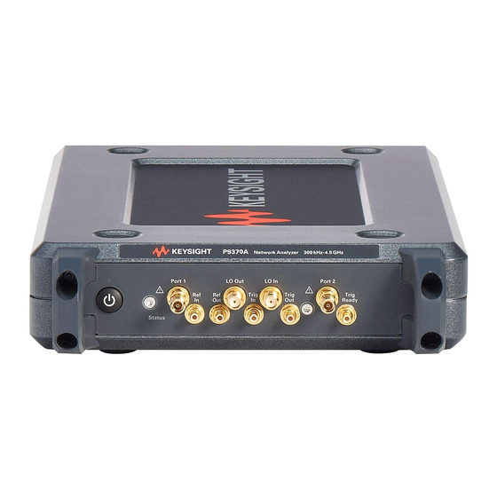
- Page 1 Keysight P937xA Streamline Series USB Vector Network Analyzers P9370A, 300 kHz to 4 GHz P9371A, 300 kHz to 6.5 GHz P9372A, 300 kHz to 9 GHz P9373A, 300 kHz to 14 GHz P9374A, 300 kHz to 20 GHz P9375A, 300 kHz to 26.5 GHz...
- Page 2 © Keysight Technologies, Inc. 2019 AGREEMENT WILL CONTROL. and are set forth specifically in writing No part of this manual may be elsewhere in the EULA. Keysight shall Technology Licenses reproduced in any form or by any be under no obligation to update,...
- Page 3 For the latest information about these products, including the P937xA Help System, instrument software upgrades, application information, and product information, browse to one of the following URLs: https://www.keysight.com/find/usb-vna To receive the latest updates by email, subscribe to Keysight Email Updates at the following URL: http://www.keysight.com/find/emailupdates Information on preventing analyzer damage can be found at: http://www.keysight.com/find/tips...
-
Page 5: Table Of Contents
Keysight Support, Services, and Assistance ........ - Page 6 Front Panel Replacement Procedure..........65 Keysight P937xA PXIe Service Guide...
- Page 7 Error Term Data ............92 Accessing the Keysight License Manager (KLM) and Installing Your License Files ..95 Firmware Upgrades .
- Page 8 Contents Keysight P937xA PXIe Service Guide...
-
Page 9: Safety And Regulatory Information Information In This Chapter
Safety and Regulatory Information Information in This Chapter Keysight P937xA PXIe Service Guide Safety and Regulatory Information Information in This Chapter This chapter provides safety information that will help protect you and your network analyzer. It also contains information that is required by various government regulatory agencies. -
Page 10: Safety Symbols
Denotes a hazard. It calls attention to a procedure which, if not correctly performed or adhered to, could result in injury or loss of life. Do not proceed beyond a warning note until the indicated conditions are fully understood and met. Keysight P937xA PXIe Service Guide... -
Page 11: General Safety Considerations
P937xA exceeds the full temperature range, always allow it to cool before touching it or removing it from the chassis. This product is designed for use in Installation Category II and Pollution Degree 2 environment. Keysight P937xA PXIe Service Guide... -
Page 12: Electrostatic Discharge Protection
500 volts. Figure 1-1 ESD protection setup Unpack the P937xA network analyzer from the shipping containers. Keep the black plastic port protectors and the shipping containers for possible reuse. Keysight P937xA PXIe Service Guide... -
Page 13: Inspect For Damage
After unpacking a network analyzer, inspect it for any shipping damage. Report any damage to the shipping agent immediately, as such damage is not covered by the warranty. To avoid damage when handling the network analyzers, do not touch exposed connector pins. Keysight P937xA PXIe Service Guide... -
Page 14: Regulatory Information
- IEC/EN 61326-1 - CISPR Pub 11 Group 1, class A - AS/NZS CISPR 11 - ICES/NMB-001 This ISM device complies with Canadian ICES-001. Cet appareil ISM est conforme a la norme NMB-001 du Canada. Keysight P937xA PXIe Service Guide... -
Page 15: Safety
- Acoustic noise emission - LpA <70 dB - Operator position - Normal operation mode per ISO 7779 Complies with the following standard (dates and editions are cited in the Declaration of Conformity): IEC/EN 61010-1. Keysight P937xA PXIe Service Guide... -
Page 16: Instrument Markings
This product complies with all relevant directives. The Keysight email address is required by EU directives applicable to our product. The CSA mark is a registered trademark of the CSA International. -
Page 17: For The Ac/Dc Adapter
To prevent electrical shock do not remove covers. Use only the designated AC/DC adapter supplied with the instrument. Use a Keysight supplied power cord that is the same or better electrical rating. Operated at an ambient temperature: 0 to 40°C.... - Page 18 The AC/DC adapter is for indoor use only. Never use a modified or damaged charger. Use the original AC–DC adapter ONLY. The AC/DC adapter is designed for use in Installation Category II and Pollution Degree 2 per IEC 61010-1. Keysight P937xA PXIe Service Guide...
- Page 19 Safety and Regulatory Information Regulatory Information Equipment Installation (AC/DC Adapter) Use Keysight supplied power cord or one with same or better electrical rating. This instrument has auto-ranging line voltage input; be sure the supply voltage is within the specified range and that voltage fluctuations do not to exceed 10 percent of the nominal supply voltage.
-
Page 20: Declaration Of Conformity
Safety and Regulatory Information Regulatory Information Declaration of Conformity A declaration of conformity is available upon request, or a copy is available on the Keysight Technologies Web site at http://www.keysight.com/go/conformity or by contacting Keysight - see “Contacting Keysight” on page Equipment Ratings The instruments can operate with mains supply voltage fluctuations up to ... -
Page 21: General Product Information Information In This Chapter
Accessories, and Upgrades which includes a list of options, accessories, and upgrades Available available for the network analyzer. Keysight Support, Services, The Internet address (URL) for Keysight assistance. page 22 and Assistance Service and support options available. Calibration options available. -
Page 22: Maintenance
To prevent electrical shock, remove analyzer module from chassis slot for cleaning. Use a dry cloth or one slightly dampened with water to clean the external case parts. Do not attempt to clean internally. Keysight P937xA PXIe Service Guide... -
Page 23: Analyzer Options, Accessories, And Upgrades Available
Analyzer Options, Accessories, and Upgrades Available Analyzer Options, Accessories, and Upgrades Available To see a list of the options, accessories, and upgrades available for the network analyzers, including ordering information, refer to the Keysight PNA Family Microwave Network Analyzers Configuration Guide, available online at https://literature.cdn.keysight.com/litweb/pdf/5992-2823EN.pdf?id=29746... -
Page 24: Keysight Support, Services, And Assistance
— Shipping Your Network Analyzer for Service or Repair Service and Support Options The network analyzer’s standard warranty is a 1-year return to Keysight Technologies service warranty. There are many other repair and calibration options available from the Keysight Technologies support organization. These options cover a range of service agreements with varying response times. - Page 25 General Product Information Keysight Support, Services, and Assistance 5. network analyzer serial numbers. The serial number label is located on the bottom panel of the module. The serial number can also be read from the Soft Front Panel (SFP) interface, after the hardware is installed.
- Page 26 General Product Information Keysight Support, Services, and Assistance Keysight P937xA PXIe Service Guide...
-
Page 27: Tests, Adjustments, And Troubleshooting Information In This Chapter
Tests, Adjustments, and Troubleshooting Information in This Chapter Keysight P937xA PXIe Service Guide Tests, Adjustments, and Troubleshooting Information in This Chapter This chapter contains procedures to help you check, verify, adjust, and troubleshoot your network analyzer. — The checks verify the operation of the assemblies in your network analyzer. - Page 28 How to perform the verification test. How to interpret the results. Test Management A list of equipment needed and TME webpage link page 45 Environment (TME) information. Performance Tests Troubleshooting A list of troubleshooting suggestions. page 51 Keysight P937xA PXIe Service Guide...
-
Page 29: Get The Hardware Required For Your Gpib Instruments
Allow the Analyzer to Warm Up To achieve the maximum system stability, allow the network analyzer to warm up for at least 15 minutes. Review the Principles of Connector Care For online information on connector care, go to http://na.support.keysight.com/pna/connectorcare/Connector_Care.htm. Keysight P937xA PXIe Service Guide... -
Page 30: About System Verification And Performance Tests
— Complete all of the performance tests using a certified calibration kit that will be used for future measurements. This alternative verifies both the system specifications and the instrument specifications for the network analyzer. Keysight P937xA PXIe Service Guide... -
Page 31: Instrument Specifications
An illustrated outline of the performance verification procedure — for ANSI/NCSL Z540.3-206 and ISO/IEC 17025 verification, is shown in Figure 3-1 on page — for Non-Standards Compliant verification, is shown in Figure 3-2 on page Keysight P937xA PXIe Service Guide... -
Page 32: Certificate Of Calibration
If you have a measurement application that does not use all of the measurement capabilities of the network analyzer, you may ask your local Keysight Technologies service office to verify only a subset of the specifications. However, this “limited calibration” creates the possibility of making inaccurate measurements if you then use the analyzer in an application requiring additional capabilities. -
Page 33: Ansi/Ncsl Z540.3-2006 And Iso/Iec 17025 Verification
After the failure has been corrected, repeat the entire set of performance tests and generate a new set of data. Figure 3-1 ANSI/NCSL Z540.3-2006 and ISO/IEC 17025 Verification Flowchart 1. Stop only in case of a catastrophic failure or cable connector damage. Keysight P937xA PXIe Service Guide... -
Page 34: Non-Standards Compliant Verification
Troubleshoot and repair the first problem encountered without continuing to other tests. After you troubleshoot, repair, and adjust, repeat the last failed portion and generate a new set of data. Figure 3-2 Non-Standards Compliant Verification Flowchart Keysight P937xA PXIe Service Guide... -
Page 35: Preliminary Checks
This section includes system verification. If instrument specifications verification is required, contact Keysight. Refer to https://www.keysight.com/find/usb-vna. A network analyzer measurement “system” includes the network analyzer, calibration kit, test cables, and any necessary adapters. - Page 36 4. If shorts and opens are not connected to all ports, you will be prompted to connect them as they are needed. 5. The result of the Operator’s Check will be shown as a PASS or FAIL to each test (refer to Figure 3-3). Keysight P937xA PXIe Service Guide...
- Page 37 1. Clean the test ports, and the open(s) or short(s), and torque to specification. Repeat the check. 2. If the check still fails, return the network analyzer to Keysight. See “Shipping Your Network Analyzer for Service or Repair” on page...
-
Page 38: System Verification
Measurement uncertainty is defined as the sum of the residual systematic (repeatable) errors, and the random (non-repeatable) errors in the measurement system after calibration. The systematic errors are: — directivity — source match — load match Keysight P937xA PXIe Service Guide... -
Page 39: Measurement Traceability
This is accomplished by measuring the devices in a Keysight verification kit. The measurement of the devices in the verification kit has a traceable path... -
Page 40: Performing System Verification
Each time through the verification process, you are prompted to make necessary connections and perform or recall a calibration as part of performing the verification. If you select to perform a calibration, you are guided through Keysight P937xA PXIe Service Guide... - Page 41 It is highly recommended that the test port cables be regularly tested. If the system verification is performed with a non-Keysight cable, ensure that the cable meets or exceeds the specifications for the test cable specified in Table 3-1.
- Page 42 Figure 3-7 on page —Print Graphs: Prints the verification data in graphical form. The graphical form includes measured data trace, factory supplied data trace, and uncertainty limits. For an example, refer to Figure 3-8 on page Keysight P937xA PXIe Service Guide...
- Page 43 4. If the analyzer still fails the test, check the measurement calibration by viewing the description of the error terms. For more information, refer to the TME webpage at http://cal.software.keysight.com. 5. Refer to Figure 3-6 on page 42 for additional troubleshooting steps. Keysight P937xA PXIe Service Guide...
- Page 44 At the top of the printed output is the name of the device, the serial number of the device, and the date tested. Each S-parameter measurement result is printed with frequency tested, lower and upper limit lines, the measured data, and the result of the test. Keysight P937xA PXIe Service Guide...
- Page 45 — Data measured at the factory from the verification kit. Labeled as B in Figure 3-8. — Upper and lower limit points as defined by the total system uncertainty system. Labeled as C in Figure 3-8. Keysight P937xA PXIe Service Guide...
- Page 46 Tests, Adjustments, and Troubleshooting System Verification Figure 3-8 Example of Printed Graphical Verification Results Keysight P937xA PXIe Service Guide...
-
Page 47: Test Management Environment (Tme) Performance Tests
Alternate models are also listed but should be considered a lower priority. All equipment is Keysight, Agilent, or Hewlett Packard unless otherwise specified. Refer to each individual test for specific setup configurations. The computer and all test equipment are connected to the unit under test (UUT) using GPIB and PXI. -
Page 48: Guidelines For Ordering Power-Sensor Calibration Service
1. Order Option 1A7 when ordering new power sensors that will be used as working standards in N7800A TME calibrations. 2. In the Americas region, order the Keysight Cal + Measurement Uncertainty for power sensor recalibration. 3. Outside the Americas region, order ISO 17025/ILAC-G8 calibration service for power sensor recalibration. - Page 49 Recommended Lab Standards and Special Cal Options website. 5. The Keysight Option H99 is a special option for the Roseville Service Center [only] which provides a CD with calibration data included as a .csv file in TME N7800A format for all power sensors used with the N7800A TME application.
-
Page 50: Adjustments
3. In the Select Desired Adjustment dialog box, click 10 MHz Freq Adjustment. 4. Follow the instructions and prompts as they are displayed. Ensure the GPIB settings are correct if using the automated mode of operation. Keysight P937xA PXIe Service Guide... -
Page 51: Source Adjustment
3. In the Select Desired Adjustment dialog box, click Source Adjustment. 4. Follow the instructions and prompts as they are displayed. If using a power meter, ensure the GPIB settings for the sensor(s) are correct in the dialog box. Keysight P937xA PXIe Service Guide... -
Page 52: Receiver Adjustment
3. In the Select Desired Adjustment dialog box, click Receiver Adjustment. 4. Follow the instructions and prompts as they are displayed. If using a power meter, ensure the GPIB settings for the sensor(s) are correct in the dialog box. Keysight P937xA PXIe Service Guide... -
Page 53: Troubleshooting
5. If multiple analyzer P937xA’s are present, make sure the cables connecting the P937xA’s are fully inserted on the front panels. For information on installing cables to multiple analyzer modules, refer to the online Startup Guide at http://literature.cdn.keysight.com/litweb/pdf/P9370-90001.pdf. Keysight P937xA PXIe Service Guide... - Page 54 10. If the problem is thought to be due to firmware, check to see if the instrument has the latest firmware before troubleshooting further. Check for firmware updates at https://www.keysight.com/find/usb-vna. 11. If the necessary test equipment is available, perform the “The Operator’s Check” on page 33 “System Verification” on page Keysight P937xA PXIe Service Guide...
-
Page 55: Replaceable Parts Listings Information In This Chapter
— contains ordering information for new assemblies. Section Title Summary of Content Start Page Ordering Information How to order a replaceable part from Keysight Technologies. page 54 Assembly Replacement The correct sequence for determining the failure of and page 55 Procedure replacing a defective assembly. -
Page 56: Ordering Information
Ordering Information To order a part listed in the replaceable parts lists: — include the part number — indicate the quatity required — Contact Keysight Technologies for instructions on where to send the order. Refer to “Contacting Keysight” on page 2-22. -
Page 57: Assembly Replacement Procedure
Step 3. Replace the faulty assembly and determine what adjustments and performance tests are necessary. Refer to Chapter 5, “Removal and Replacement Procedures.” Step 4. Perform the “The Operator’s Check” on page 3-33 “System Verification” on page 3-36. Keysight P937xA PXIe Service Guide... -
Page 58: Replaceable Parts Listings
Descriptions and part numbers for the assemblies and parts shown in the above illustration can be found at the following Table 4-1. Miscellaneous parts and accessories not illustrated in Figure 4-2 are listed under “Miscellaneous Parts” on page 4-58. Keysight P937xA PXIe Service Guide... - Page 59 Front handle P9375-40011 Front impact cover Not Shown P9370-80002 P937xA nameplate kits a. If you are replacing a new chassis, you must also purchase the P9370-80002 nameplate kits, which include all the models nameplate label. Keysight P937xA PXIe Service Guide...
-
Page 60: Miscellaneous Parts
Replaceable Parts Listings Replaceable Parts Listings Miscellaneous Parts Figure 4-2 P937xA USB VNA Miscellaneous Parts Keysight P937xA PXIe Service Guide... -
Page 61: Accessories Part
Port 1 and Port 2 Dust Cap Not Shown 1401-0431 SMB Connectors Dust Cap Accessories Part Description Part Number USB 3.0 cable P9375-60010 External Power Supply Desktop adapter 0950-6128 90-264 AC 15 VDC 6 A 90 W Keysight P937xA PXIe Service Guide... - Page 62 Replaceable Parts Listings Replaceable Parts Listings Keysight P937xA PXIe Service Guide...
-
Page 63: Removal And Replacement Procedures
STOP!!! Please read all content before proceeding with this repair procedure. This repair must be done at a service center! If you think you may not be qualified to do the work, or need advice, contact Keysight. Refer to “Keysight Support, Services, and Assistance” on page... -
Page 64: Electrostatic Discharge (Esd) Protection
To reduce the chance of electrostatic discharge, follow all of the recommendations outlined in “Electrostatic Discharge Protection” on page 12, for all of the procedures in this chapter. Keysight P937xA PXIe Service Guide... -
Page 65: Connector Replacement Procedure
2. Place the “spark plug” adapter on the nut of the connector you are going to replace. The adapter must fit snugly into the slots of the nut. Refer to Figure 5-2 on page Figure 5-1 Tools and Parts Keysight P937xA PXIe Service Guide... -
Page 66: Replacement Procedure
— “Source Power Accuracy Test” — “Source Maximum Power Output Test” — “Calibration Coefficients Test” If any of the tests fail, perform the Adjustments (refer to “Adjustments” on page 48), then repeat the tests. Keysight P937xA PXIe Service Guide... -
Page 67: Front Panel Replacement Procedure
2. When reinstalling the dress nut in step 3, make sure install in the sequences 3a flat washer, follow by 3b lock washer and 3c dress nut. Secure with 1/4-inch nut setter bit set to 6 in-lbs. Keysight P937xA PXIe Service Guide... - Page 68 Removal and Replacement Procedures Front Panel Replacement Procedure Figure 5-4 Removing and replacing A3 Front Panel Assembly Keysight P937xA PXIe Service Guide...
- Page 69 Removal and Replacement Procedures Front Panel Replacement Procedure Figure 5-5 Light Pipe Assembly Keysight P937xA PXIe Service Guide...
-
Page 70: Chassis Replacement Procedure
6. Slide the A2 module out from the chassis. Each module is individually serialized, serial numbers are labeled into the body of each module known as manufacturing ID. Record down the module manufacturing ID as this is needed for the post replacements procedure. Keysight P937xA PXIe Service Guide... - Page 71 5. Perform the post-repair steps, verifications, and performance tests that pertain to this removal procedure. Refer to Chapter 3, “Tests, Adjustments, and Troubleshooting”, on page 25 Figure 5-6 Nameplate Overlay for P937xA Keysight P937xA PXIe Service Guide...
- Page 72 Removal and Replacement Procedures Chassis Replacement Procedure Figure 5-7 Secure Regulatory Plate (P9375-00007, 0515-1227 (x4)) Keysight P937xA PXIe Service Guide...
-
Page 73: Module Replacement Procedure
4. Remove the front panel. Refer to “Removing and Replacing the A3 Front Panel Assembly” on page 5. Remove the light pipe from the module. Refer to the Figure 5-5 on page 6. Slide the A2 module out from the chassis. Keysight P937xA PXIe Service Guide... - Page 74 3. Perform the post-repair steps, verifications, and performance tests that pertain to this removal procedure. Refer to “Post-Repair Procedures” on page When slide in the module, make sure the PCB board sitting in between the groove on the both side . Refer figure below. Keysight P937xA PXIe Service Guide...
-
Page 75: Post-Repair Procedures
No adjustment needed Perform the OF Ingot Utilities Operator’s check All TME based tests that apply A3 Front Panel No adjustment needed Operator’s check Assembly Connector No adjustment needed Operator’s check All TME based tests that apply Keysight P937xA PXIe Service Guide... - Page 76 Consult the user guide (P9370-90001) for the minimum requirements of the system controller. Step 3. Download and install the “OF Ingot Utilities”. You will need to contact the Keysight factory support node to request the OF Ingot Utilities software. Step 4. Run the OF Ingot Utilities.
- Page 77 Removal and Replacement Procedures Post-Repair Procedures b. If the chassis does not show, press the Refresh button. Keysight P937xA PXIe Service Guide...
- Page 78 Post-Repair Procedures Step 6. Locate the “Chassis configuration file” area of the menu (at the bottom) and press the Open button. Step 7. In the “Open” Dialog box locate the directory “Instruments” and select it. Keysight P937xA PXIe Service Guide...
- Page 79 Removal and Replacement Procedures Post-Repair Procedures Step 8. Select the directory for the product number you are working on. Step 9. The file name will now appear in the “Chassis configuration file:” Keysight P937xA PXIe Service Guide...
- Page 80 Removal and Replacement Procedures Post-Repair Procedures Step 10. Press the “Load” button to load the Chassis configuration file. Keysight P937xA PXIe Service Guide...
- Page 81 Removal and Replacement Procedures Post-Repair Procedures Step 11. Select the Chassis Configuration Tab. Keysight P937xA PXIe Service Guide...
- Page 82 (MY/USXXXXXXXX) can be found on the Chassis regulatory plate from the original unit. 1. Model Number = Model number of the USB VNA b. Serial Number = Serial number of the USB VNA Figure 5-8 Regulatory Plate on Chassis Keysight P937xA PXIe Service Guide...
- Page 83 Step 13. Keying the slot configuration model number and manufacturing number. a. Model number = Model number of the USB VNA b. Manufacturing Number = Manufacturing number off of the label on the PXI module. Refer to Figure 5-7 on page Keysight P937xA PXIe Service Guide...
- Page 84 Removal and Replacement Procedures Post-Repair Procedures Example of all the fields filled in as below: Keysight P937xA PXIe Service Guide...
- Page 85 All of the licenses in your UBS VNA need to be re-host to the new hostID . Contact Keysight Technologies factory support early in your repair process to receive your licenses in a timely manner. See “Contacting Keysight”...
- Page 86 Removal and Replacement Procedures Post-Repair Procedures Go to Help> About Network Analyzer, you will need to provide Keysight with the following information: - model number • serial number • HostID Instrument information is available in the USB network analyzer - on the toolbar, click Help, then click About Network Analyzer.
- Page 87 It is recommended that a full instrument calibration be performed using the TME Performance Tests. Refer to the TME webpage at http://cal.software.keysight.com. If any of the tests fail, perform the Adjustments (refer to “Adjustments” on page 48), then repeat the tests.
- Page 88 Removal and Replacement Procedures Post-Repair Procedures Keysight P937xA PXIe Service Guide...
-
Page 89: General Product Information Information In This Chapter
Error Terms How to use error term data as a diagnostic tool. page 88 Accessing the Keysight How to use Keysight License Manager (KLM) to install your page 95 License Manager (KLM) and licenses on your instrument. Installing Your License Files Firmware Upgrades How to get firmware upgrades. -
Page 90: Error Terms
— A sudden shift in error terms may indicate the need for troubleshooting. Troubleshooting Refer to error term descriptions in “Error Term Data” on page Always suspect calibration devices, cables, or improper connector maintenance as the primary cause of an error term anomaly. Keysight P937xA PXIe Service Guide... -
Page 91: Performing Measurement Calibration
Flowgraph of 1-Port Error Terms for Port 1 Where: E = Error term Subscript: D = Directivity S = Source Match R = Reflection Tracking The error terms are the same for a 1-port measurement on Port 2 (S Keysight P937xA PXIe Service Guide... -
Page 92: Manual Access To Error Terms
R = Reverse measurement (Port 2 to Port 1) Manual Access to Error Terms Soft Front Panel Access to Error Terms Ensure the calibration correction is active by making sure that the check box for Correction on/OFF has been selected. Keysight P937xA PXIe Service Guide... - Page 93 “Error Term Data” on page 92, or to previously measured data, or to the uncorrected performance specifications listed in Table 6-1 on page 7. Print numerical data or print a plot of the measurement results. Keysight P937xA PXIe Service Guide...
-
Page 94: Error Term Data
25 °C ±5 °C, with less than 1 °C deviation from the cali- bration temperature. 2. All crosstalk values are typical. If Error Terms Seem Worse than Expected To verify that the system still conforms to specifications, perform a system verification. Refer to “System Verification” on page Keysight P937xA PXIe Service Guide... - Page 95 “thru” configuration during the calibration procedure. The measurements most affected by load match errors are all transmission measurements, and reflection measurements of a low insertion loss, 2-port device, such as an airline. Keysight P937xA PXIe Service Guide...
- Page 96 E Isolation, or crosstalk, is the uncorrected forward and reverse isolation error terms that represent leakage between the test ports and the signal paths. The isolation error terms are characterized by measuring the transmission (S Keysight P937xA PXIe Service Guide...
-
Page 97: Accessing The Keysight License Manager (Klm) And Installing Your License Files
This section assumes you have completed the Getting Prepared section (i.e., That you have already received your instrument’s license key files from Keysight and downloaded them to a USB stick. And, that your USB stick is inserted in your instrument’s PC controller. - Page 98 7. Click on the license key file (#######.lic) > Open Figure 6-5 Select License File(s) to Install Window 8. The Select License File(s) window closes and the Keysight License Manager window should now display all of your license files. Keysight P937xA PXIe Service Guide...
- Page 99 General Product Information Accessing the Keysight License Manager (KLM) and Installing Your License Files If you have any problems installing your files, refer to “Contacting Keysight” on page 9. Shut down the instrument application and restart. Optional: Cycle power on the instrument to activate the newly installed option upgrade(s).
-
Page 100: Firmware Upgrades
1. With the Network Analyzer application running, click Help > About Network Analyzer. A dialog box showing the current installed Application Code Version is displayed. 2. To determine if a firmware update is available, proceed to: https://www.keysight.com/find/usb-vna Keysight P937xA PXIe Service Guide... - Page 101 2-22 source adjustment 3-49 source match error terms information, where to find the latest 1-93 specifications instrument specifications instrument 3-29 3-29 system Isolation error terms 3-28 1-94 Keysight P937xA PXIe Service Guide...
- Page 102 Keysight P937xA PXIe Service Guide...
- Page 103 This information is subject to change without notice. © Keysight Technologies 2019 Edition 1, April 2019 *P9370-90004* P9370-90004 www.keysight.com...
Need help?
Do you have a question about the P937 A Series and is the answer not in the manual?
Questions and answers