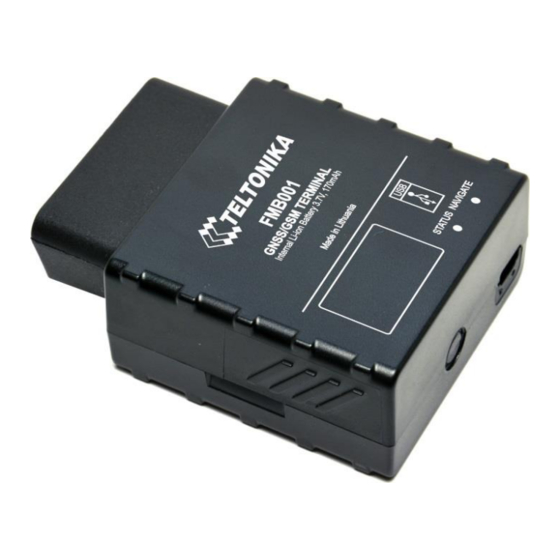
Teltonika FMB001 User Manual
Gnss/gsm terminal, internal li-ion battery 3.7v, 170mah
Hide thumbs
Also See for FMB001:
- Quick manual (18 pages) ,
- Getting started (14 pages) ,
- First start-up quick start manual (6 pages)
Table of Contents
Advertisement
Quick Links
Download this manual
See also:
Quick Manual
Advertisement
Table of Contents

Related Manuals for Teltonika FMB001


Summary of Contents for Teltonika FMB001
- Page 1 FMB001 User Manual V0.17...
-
Page 2: Table Of Contents
..............11 ECHNICAL NFORMATION ABOUT INTERNAL BATTERY ....................12 LECTRICAL CHARACTERISTICS ....................12 BSOLUTE AXIMUM ATINGS CONNECTION, PINOUT, ACCESSORIES .................. 13 FMB001 : ............13 OW TO INSERT MICRO CARD INTO DEVICE FMB001 ....................14 NSTALLING DRIVERS OBD II ..........................17 LED ........................ - Page 3 ....................38 CENARIOS CCELEROMETER 5.9.1 Excessive Idling ....................... 38 5.9.2 Towing detection ....................39 5.9.3 Unplug Detection ....................40 5.9.4 Crash detection ....................... 40 5.9.5 Crash Trace operation .................... 41 5.10 ....................41 EOFENCING SETTINGS 5.11 ......................43 ANUAL EOFENCE 5.12 ........................
- Page 4 6.2.16 NTP server 2 (ID=903) ..................... 69 ......................69 ECORDS PARAMETERS 6.3.1 Sorting (ID=1002) ....................69 6.3.2 Open Link Timeout (ID=1000) ................. 69 6.3.3 Server Response Timeout (ID=1001) ............... 69 ....................... 70 PARAMETERS 6.4.1 GPRS content activation (ID=2000) ............... 70 6.4.2 APN Name (ID=2001) ....................
- Page 5 6.6.6.4 Min Speed (ID=10253) ......................78 Min Distance (ID=10151) ........................78 6.6.6.5 Min Saved Records (ID=10254) ................... 78 6.6.6.6 Send Period (ID=10255) ...................... 79 ......................79 EATURES ARAMETERS 6.7.1 Green driving priority (ID=11000) ................79 6.7.2 Max Acceleration Force (ID=11004) ............... 79 6.7.3 Max Braking Force (ID=11005) ................
- Page 6 6.10.1.8 Fuel Consumption on Idling [L/h] (ID=11907) ..............87 6.10.1.9 Higher Speeds Add [%] (ID=11908) ................... 87 6.10.1.10 Highway Consumption every km/h (ID=11909) .............. 87 6.11 ....................88 CENARIOS CCELEROMETER 6.11.1 Unplug Detection ....................88 6.11.1.1 Scenario settings (ID=11500) .................... 88 6.11.1.2 Eventual records (ID=11501) ....................
-
Page 7: Introduction
The device uses a 10 V...30 V DC power supply. The nominal voltage is 12 V DC. The allowed range of voltage is 10 V...30 V DC. To avoid mechanical damage, it is advised to transport the FMB001 device in an impact- proof package. -
Page 8: Legal Notice
Note: Monitorable basic vehicle parameters depend on vehicle mark and model. Package contents The FMB001 device is supplied to the customer in a cardboard box containing all the equipment that is necessary for operation. The package contains: Already implemented FMB001 device into case;... -
Page 9: Basic Characteristics
Basic characteristics GSM / GPRS / GNSS features: • Teltonika TM2500 quad band module (GSM 850 / 900 / 1800 / 1900 MHz); • GPRS class 12 (up to 240 kbps); • SMS (text, data). • Integrated GNSS receiver • Up to -165 dBm GNSS receiver sensitivity. -
Page 10: Technical Features
Storage relative humidity 5 ... 95 % (no condensation) Internal fuse: 3A, 125V Weight: 63 g. Table 1. FMB001 specifications Energy consumption has been tested at 12V voltage with no battery charging. When in Deep Sleep mode no data storing and sending is activated. -
Page 11: Technical Information About Internal Battery
0.64 - 0.66 0 – 45 battery Table 2 Battery specifications FMB001 internal battery is used for detecting external voltage disconnection. CAUTION: RISK OF EXPLOSION IF BATTERY IS REPLACED BY AN INCORRECT TYPE. DISPOSE OF USED BATTERIES ACCORDING TO THE INSTRUCTIONS. -
Page 12: Electrical Characteristics
Electrical characteristics VALUE Min. Typ. Max. Unit CHARACTERISTIC DESCRIPTION Supply Voltage: Supply Voltage (Recommended Operating Conditions) Digital Input: Input resistance (DIN1) kΩ Input Voltage (Recommended Operating Supply Conditions) voltage Input Voltage threshold (DIN1) Absolute Maximum Ratings VALUE Min. Typ. Max. Unit CHARACTERISTIC DESCRIPTION Supply Voltage (Absolute Maximum Ratings) -
Page 13: Connection, Pinout, Accessories
3 CONNECTION, PINOUT, ACCESSORIES How to insert micro SIM card into FMB001 device: Remove FMB001 cover Insert micro SIM card as shown (bottom slot) Insert SD card as shown (top slot). *Available for devices manufactured before 2018-04... -
Page 14: Installing Fmb001 Drivers
Connect battery as shown to device Attach cover Device is ready Installing FMB001 drivers Software requirements: • Operating system 32-bit and 64-bit: Windows XP with SP3 or later, Windows Vista, Windows 7. • MS .NET Framework V3.5 or later (http://www.microsoft.com http://avl1.teltonika.lt/downloads/tavl/Framework/dotnetfx35setupSP1.zip). - Page 15 Installing drivers: Extract and run FP_INBOX_InstallDriver_v1.1032.3.exe. This driver is used to detect FMB001 device connected to the computer. Click 'Next' in driver installation window (figures below): Figure 2 Driver installation window This will launch device driver installation wizard. In the following window click ‘Install’...
- Page 16 Figure 4 Driver installation window You have now installed drivers for FMB001 device successfully.
-
Page 17: Obd Ii
Figure 5 OBD II pinout Pin Name Description Ignition input PWM_BUS+/VPW GND (-) Ground pin. GND (-) Ground pin. CAN_H K-Line PWM_BUS- CAN_L L-Line Power range +(10...30) V DC to ground Power +(1030) V DC Table 3 FMB001 pinout description... -
Page 18: Navigate Led
While in sleep mode, FMB001 turns GPS module off and it is still making new periodic records. As a result power usage decreases, in turn saving vehicle battery. -
Page 19: Deep Sleep Mode
Active Data Link Timeout parameter, that FMB001 could close GPRS link. • Send period (Data Acquisition Mode settings) minus Active Data Link Timeout must be more than 90 sec., that FMB001 could close GPRS link for at least 90 sec. • Sleep timeout is reached;... -
Page 20: Virtual Odometer
It keeps adding these intervals until it is time to make a record, then FMB001 records its location and adds odometer value, which is equal to the sum of all distances, measured every second. -
Page 21: Over Speeding Scenario
Green driving uses GPS data. Note: Green Driving and Eco Driving Scenarios are a factor on various cars and various drivers testing phase and can be subject to changes. Teltonika is constantly working on improvement of the functionality of the devices, and strongly recommends using the latest version of the firmware. -
Page 22: Towing Detection
GSM is not available FMB001 will start storing records to flash memory. It is possible to store up to 1 056 512 data records with 128mb internal flash memory. It will send data later when GPRS is available again. Note that FMB001 can have memory full of records. In such case it... - Page 23 FMB001 Configurator program and then connecting to FMB001 device via Connect button located in Online menu part. FMB001 has one user editable profile, which can be loaded from device, and saved. User can also revert to default settings, by pressing Reset to defaults button.
-
Page 24: Status Tab
Status tab Main Buttons description: ‘Load from file’ – loads saved configuration. ‘Load from device’ – loads configuration from device. ‘Save to file’ – saves configuration. ‘Save to device’ – saves configuration to device. ‘Update firmware’ – updates firmware button. ‘Read records’... - Page 25 Log/Dump To make a log, just press on “Log” button in the Maintenance tab and device will start to collect log for 10 minutes. After that – it will save it into “My Documents” on your PC, “Open directory” button will guide you to the file. “Dump”...
-
Page 26: Security Tab
Security tab Keyword SMS (GPRS) commands: "setkey <oldkeyword> <newkeyword>" - Set new or change the keyword. Configuration should be not locked. Example: New keyword (set): <name>{space}<pass>{space}setkey{space}{space}{space}<newkeyword> Change keyword (change): <name>{space}<pass>{space}setkey{space}<oldkeyword>{space}<newkeyword> "delkey <keyword>" - Deletes current keyword. Configuration keyword should be configured and not locked. - Page 27 2. Ignition source, where user can choose between power voltage, digital input 1 and accelerometer ignition sources 3. Object Motion Detection Settings, where user can configure 3 ways how FMB001 will detect stopped movement, and change its working mode (for working modes, read section 5.8);...
- Page 28 (depends on Object Motion Detection Settings). It allows filtering GPS jumps when object is parked (is not moving) and GPS position is still traced. Figure 9 System settings configuration...
-
Page 29: Gsm Settings, Gprs Part
AVL application. Activate Data Link Timeout is used to set timeout of link between FMB001 and AVL application termination. If FMB001 has already sent all records it waits for new records before... -
Page 30: Sms/Call Settings
Essential fields in ‘SMS’ part are ‘Login’ and ‘Password’. The login and password are used with every SMS sent to FMB001. If login and password are not set, in every SMS sent to FMB001 device two spaces before command have to be used (<space><space><command>). - Page 31 not generate IDD Prefix, which depends on location of phone). If no numbers are entered, configuration and sending commands over SMS are allowed from all GSM numbers. SMS data sending settings – enable or disable periodic data and event SMS usage. This setting does not affect replies to SMS request messages –...
- Page 32 This event can be triggered by ever I/O element. Then any of the I/O elements is triggered, FMB001 sends a configured SMS message to a defined phone number. If SMS events is activated, but there are no numbers defined in SMS events PreDefined Numbers list (figure 20), then the device will not send any messages.
-
Page 33: Gsm Settings, Operator List
Any not written operator in roaming operator list (not home operator) will be recognized as unknown operator and FMB001 will work in Unknown mode (make sure it is configured to allow data sending). -
Page 34: Features Settings
Figure 13 Operator list configuration Features settings In Features window four different scenarios are available. -
Page 35: Eco/Green Driving
Figure 16 Scenarios configuration 5.8.1 Eco/Green Driving Scenario is activated, when vehicle exceeds one of Max. Acceleration, Max Braking or Max Cornering parameters value. You can configure Max. Acceleration and Max. Braking parameters in m/s² (meter/second²) units and Max. Cornering parameter in rad/s units, the source of data and Duration. -
Page 36: Accelerometer Calibration
If any of three cases are satisfied event is generated. Record is saved and sent to server (FMB001 must be configured properly). Event value is multiplied by 100 before sending/saving record to get more precision when displaying data*. - Page 37 • second vector was not saved yet; • vehicle driving in the same direction with 5⁰ tolerance; • vehicle speed increase by 7km/h within 1 second. For next vector. Second vector will be taken if all conditions match. Immediately after second vector is received, it will be multiplied by first (ground) vector, the result of these vectors is vector multiplication cross product which is the right side of a car.
-
Page 38: Over Speeding
2. When speed is higher than highway speed, FMB001 adds highway fuel consumption x % of highway fuel consumption every y km/h, by default FMB001 adds 20% every 50 km/h. It means that fuel consumption is (1.2 * Highway Fuel Consumption) on 140 km/h speed, (1.4 * Highway Fuel Consumption) on 190 km/h speed. -
Page 39: Towing Detection
Duration (in ms), check Ignition state. If Ignition is still OFF during configured "Ignition check after Event Timeout" time, then event is generated. If configured - sends sms event or makes a call. Function will be reactivated after FMB001 again detects change of Ignition state from ON to OFF. Figure 7 Towing detection configuration Activation timeout –... -
Page 40: Unplug Detection
Threshold and duration values are set depending of accident power which you want to detect. FMB001 can detect a slight tapping on the device (Threshold=100mg, Duration=1ms) or can detect severe accident (Threshold=4000mg,... -
Page 41: Crash Trace Operation
Every generated record will have accelerometer X Y Z values included. Each record will have accurate timestamps in milliseconds (for detailed crash trace record structure refer to FMB001 protocol document). Usually between 20 to 30 records is generated on crash event detection. - Page 42 AutoGeofencing option can be configured by following parameters visible in figure 19 below. Activation TMO – Time period before Geofence is activated after vehicle stops. Deactivate By: Ignition – If ignition becomes high it will disable AutoGeofenze Zone; Power Voltage – if power voltage enters entered value it will disable AutoGeofenze Zone.
-
Page 43: Manual Geofence
5.11 Manual Geofence FMB001 has 50 configurable Geofence zones and it can generate an event when defined Geofence zone border is crossed. Frame border – frame border is an additional border around Geofence zone. It is additional area around defined zone used to prevent false event recording when object stops on the border of the area and because of GNSS errors some records are made inside area and some –... -
Page 44: Trip Settings
Figure 21 Geofence configuration 5.12 Trip settings Trip scenario offers user to configure Trip feature. Start Speed – GPS speed has to be greater than the specified Start Speed in order to detect Trip Start. Ignition Off Timeout – timeout to wait if ignition was off, to detect Trip stop. Continuous distance counting –... - Page 45 Figure 22 Trip configuration Figure 23 Trip continuous distance counting parameter example Advanced Trip Settings Advanced trip settings allow configure number of Eco Score allowed events in 100 km and enable or disable iButton remember funkcionality.
- Page 46 – how much ECO events is allowed in 100 km. I/O Eco score must Eco Score allowed events be enabled to get value into server. ECO scoring is differentiated by separate Trips. There are six ECO evaluation events: ▪ Harsh acceleration ▪...
-
Page 47: Blue-Tooth
FMB001_<imei last chars> Local PIN - PIN code which will be used when external device will try to pair with FMB001. NOTE: FMB001 supports ONE connection at a time. NOTE: FMB001 can see up to 10 available devices. If there are more then 10, with each scanning the list may change. -
Page 48: Connecting To Device Via Blue-Tooth
External Name – Blue-tooth name of you NOTE: FMB001 supports ONE connection at a time. NOTE: FMB001 can see up to 10 available devices. If there are more then 10, with each scanning the list may change. Figure 25 MAC list Figure shows list of Authorized MAC addresses which are allowed to connect to FMB001. - Page 49 These are instructions how to easily prepare Blue-tooth Hands Free device connection to FMB device. First we need to configure FMB device Blue-tooth settings for proper connection to this hands-free unit. These are required steps: 1. Connect FMB device to PC using USB cable. 2.
-
Page 50: Device's Log Using Your Mobile Phone
5555. Paired device will show up in paired device list. Now download from play store/app store terminal for Blue-tooth. E.g BlueTerm. Run app, click find>connect to your paired device. Now we need to send command to FMB001 through Blue- tooth terminal, type: .log:1 Hands Free device Blue-tooth connection pairing instructions depends on specific model. - Page 51 Device will respond Debug enabled and FMB001 log will show up. Do not forget to start save log file to mobile phone. Device debug over Android smartphone 1. Scan for visible BT devices using your Android smartphone and connect to your FMB device.
- Page 52 .log:1 4. Wait ~10 minutes and press “Save” button in menu. You will find saved log file in device folder (My Files/Blue-toothTerminal), select log files and press button Share via Email and send them to the Teltonika support.
-
Page 53: Blue - Tooth 4.0
In order to pair FMB device with Android smartphone, make sure that BT radio is enabled (visible) in device configuration. It can be checked via SMS command too: getparam 800 The answer has to be 2, which means “Enabled and visible”. Note: Unfortunately it is not possible to do the same on iPhone, because there is no native SPP Blue-tooth profile support in iPhone. -
Page 54: Data Acquisition Mode Settings
FMB001 supports up to 4 sensors at the same time. For device to recognize the packets from the sensor – it’s ID must be entered in the field near the “Working mode” TZ-BT04/05 Update frequency – determines how often data will be read from sensor. - Page 55 Figure 14 Data Acquisition Mode configuration Operator search is performed every 15 minutes. Depending on current GSM operator, Home, Roaming or Unknown mode can be changed faster than every 15 minutes. This process is separate from operator search. Movement criteria are checked every second.
- Page 56 ‘Min Saved Records’ defines minimum number of coordinates and I/O data that should be transferred with one connection to server. If FMB001 does not have enough coordinates to send to server, it will check again after time interval defined in ‘Sending Period’.
- Page 57 Distance based data acquiring (Min. distance) – records are being acquired when the distance between previous coordinate and current position is greater than defined parameter value. Entering zero disables data acquisition depending on distance. Min. distance Angle based data acquiring (Min. angle) – records are being acquired when angle difference between last recorded coordinate and current position is greater than defined value.
-
Page 58: Obd Functionality Description
I/O element. Enabled or disabled field – allows enabling I/O element so it is added to the data packet and is sent to the server. By default all I/O element are disabled and FMB001 records only GNSS coordinates. - Page 59 Table 6 Permanent I/O elements Permanent I/O elements (are always sent to server if enabled) Property Name Description Ignition Logic: 0 / 1 Movement Logic: 0 / 1 0 – home on stop, 1 – home on move, 2 – Data mode roaming on stop, 3 –...
- Page 60 Sent value is multiplied by 10. Degrees ( °C ), -40 - +125; Error codes: 4000 - abnormal sensor state BLE Temp #2 3000 - sensor not found 2000 - failed sensor data parsing Sent value is multiplied by 10. Degrees ( °C ), -40 - +125;...
-
Page 61: Sms Command List
6 SMS COMMAND LIST All commands are case sensitive. While FMB001 operates in Sleep mode and user tries to send SMS message it will arrive to FMB001 device, because GSM module is enabled. Only GNSS module is disabled in sleep mode. -
Page 62: Getinfo
getparam Returns selected parameter value setparam Sets selected parameter value flush Redirects device to other server countrecs Returns record number fc_reset Resets fuel consumption parameters towingreact Towing reactivation btgetlist Returns requested Blue-tooth list(values:0, 1, 2) btgscan Starts Blue-tooth scan(values: none, 1) btvisible Sets Blue-tooth to visible with TMO btrelease... -
Page 63: Getstatus
Modem Ver Version of modem application GPS Ver Version of GPS module Hw Ver Version of hardware Device IMEI IMEI Example: Ver:01.00.17 Rev:01 Modem Ver:TM25Q_D_01.00.00.00_010 Ver:AXN_3.82_3333_1Hw Ver:FMB0_MOD2_A0:B0:C1:D0 Device IMEI:352094080000950 6.1.3 getstatus Response details Description Data Link Indicate module connection to server at the moment: 0 – Not connected, 1 –... -
Page 64: Readio
Time Actual Speed Latitude (Last good Latitude), Longitude (Last good Longitude) Google Maps Link Example: D:17/1/9 T:12:52:30 S:0.00 C:54.666042, 25.225032 Url: http://maps.google.com/?q=54.666042,25.225032&om=1speed:0 6.1.6 readio # Response details Description I/O element ID Value I/O Element value Example: Param ID:3 Value:0 6.1.7 getparam Read parameter value. -
Page 65: Countrecs
# records found on FLASH Number of records found on FLASH Minimum Records to Send: # Number of minimum saved records to send GPRS Enabled: # State of the GPRS connection, 0 – disabled; 1 – enabled Time Sync: # Indicates time synchronization on the device, 0 –... -
Page 66: Cleardtc
GPS module to sleep, in deep sleep mode (value 2) module turns GPS module to sleep and device is deregistered from network (note, that FMB001 do not receive SMS while in deep sleep). In online sleep(value 3), device behavior is the same as in deep sleep, but GSM module stays on. -
Page 67: Static Navigation (Id=106)
6.2.4 Static Navigation (ID=106) When static navigation is enabled, FMB001 filters out GPS jumps, when it is not moving. When it is disabled, it does not make any changes to collected GPS data. Minimum Maximum Recommended Goes with (depends on) -
Page 68: High Voltage Level (Id=104)
RPM, 10 – Accelerometer or Engine RPM, 11 – DIN1, Accelerometer or Engine RPM, 12 – Power Voltage or Engine RPM, 13 –DIN1, Power Voltage or Engine RPM, 14 – Accelerometer, Power Voltage or Engine RPM, 15 - DIN1, Accelerometer, Power Voltage or Engine RPM. Minimum Maximum Recommended... -
Page 69: Ntp Resync (Id=901)
6.2.15 NTP server 1 (ID=902) Minimum Maximum Default value Goes with (depends on) Value value value parameters type 55 char avl1.teltonika.lt S8[55] string 6.2.16 NTP server 2 (ID=903) Minimum Maximum Default value Goes with (depends on) Value value value parameters... -
Page 70: Gsm Parameters
ATTENTION! Some GSM operators may disconnect the device from an active data link if the device doesn’t send any data for a very long time, even if active data link timeout is set to maximum value. The amount of time that an operator keeps the link open depends solely on the operator. -
Page 71: Apn Password (Id=2003)
6.4.4 APN Password (ID=2003) Parameter defines APN password. In case operator does not use password for login, value should be empty. Minimum Maximum Recommended Goes with (depends on) Value value value value parameters type GPRS content activation 30 char (ID=2000) Empty S8[30] string... -
Page 72: Data Send Number (Id=3001)
6.5.2 Data send number (ID=3001) In this field are written GSM numbers, to which will be sent Data SMS. Minimum Maximum Recommended Goes with (depends on) Value value value value parameters type 1 digit 16 digits 6.5.3 Authorized phone numbers (ID=4000-4009) If at least one number is entered then only those number can send messages to device. -
Page 73: Incoming Call Action (Id=3005)
6.5.8 Incoming call action (ID=3005) Parameter defines action during call: 0 – do nothing, 1 – hang up, 2 – report position Minimum Maximum Recommended Goes with (depends on) Value value value value parameters type S8[17] 6.5.9 Outgoing Call Trigger (ID=3007) Parameter defines hands free call trigger: 0 –... -
Page 74: Send Period (Id=10005)
Minimum Maximum Recommended Goes with (depends on) Value value value value parameters type 6.6.1.3 Send Period (ID=10005) This parameter indicates frequency (time interval in seconds) of sending data to server. Minimum Maximum Recommended Goes with (depends on) Value value value value parameters type... -
Page 75: Min Saved Records (Id=10054)
Minimum Maximum Recommended Goes with (depends on) Value value value value parameters type Min Period (ID=10050) Min Distance (ID=10051) Min Angle (ID=10052) 6.6.2.5 Min Saved Records (ID=10054) This parameter defines minimum number of records in one data packet that can be sent to server. -
Page 76: Roaming Network Gsm Operator Code "Vehicle Moving" Parameters
6.6.4 Roaming Network GSM operator code “Vehicle MOVING” parameters 6.6.4.1 Min Period (ID=10150) This parameter indicates time interval in seconds in order to acquire new record. If value is 0 it means no records by min period will be saved. Minimum Maximum Recommended... -
Page 77: Send Period (Id=10155)
6.6.4.6 Send Period (ID=10155) This parameter indicates frequency (time interval in seconds) of sending data to server. Minimum Maximum Recommended Goes with (depends on) Value value value value parameters type Min Saved Records 2592000 (ID=10154) 6.6.5 Unknown Network GSM operator code “Vehicle on STOP” parameters 6.6.5.1 Min Period (ID=10200) This parameter indicates time interval in seconds in order to acquire new record. -
Page 78: Min Distance (Id=10251)
Min Angle (ID=10152) 6.6.6.2 Min Distance (ID=10251) This parameter indicates distance in meters in order to acquire new record. Record is stored when the distance between previous records is greater than parameter’s value. If value is 0 it means no records by min distance will be saved. Minimum Maximum Recommended... -
Page 79: Send Period (Id=10255)
6.6.6.6 Send Period (ID=10255) This parameter indicates frequency (time interval in seconds) of sending data to server. Minimum Maximum Recommended Goes with (depends on) Value value value value parameters type Min Saved Records 2592000 (ID=10254) Features Parameters 6.7.1 Green driving priority (ID=11000) Defines priority of green driving scenario: 0 –... -
Page 80: Green Driving Send Sms To (Id=7034)
value value parameters type 6.7.6 Green driving Send SMS to (ID=7034) Enable/disable sms event sending. 0 – Disable, 1-10 – sms will be sent to configured GSM number. Minimum Maximum default value Goes with (depends on) Value value value parameters type Unit8 6.7.7 Green driving SMS text (ID=8034) -
Page 81: Excessive Idling Priority (Id=11200)
6.7.12 Excessive idling priority (ID=11200) Defines priority of Excessive idling scenario: 0 – disabled, 1 – low, 2 – high, 3 – panic Minimum Maximum Recommended Goes with (depends on) Value value value value parameters type 6.7.13 Eventual records (ID=11203) Disables (0) or enables (1) eventual records with idling value Minimum Maximum... -
Page 82: Start Speed (Id=11803)
0 – disabled, 1 – low, 2 – high, 3 – panic Minimum Maximum Default value Goes with (depends on) Value value value parameters type 6.7.19 Start Speed (ID=11803) This parameter represents speed, which is detected as minimum speed to indicate TRIP START and generate event. -
Page 83: Activation Timeout (Id=20003)
6.8.3 Activation Timeout (ID=20003) Parameter represents AutoGeofencing activation timeout in seconds. Minimum Maximum Recommended Goes with (depends on) Value value value value parameters type AutoGeofencing priority 65535 (ID=20000) 6.8.4 Deactivate by (ID=20005) Parameter defines Autogeofence deactivation source. Value 0 – for Ignition, - Power Voltage, Digital Input 1 Minimum Maximum... -
Page 84: Sms Text (Id=8030)
6.8.8 SMS Text (ID=8030) Configure AutoGeofence sms event text here. Minimum Maximum Default value Goes with (depends on) Value value value parameters type AutoGeofence S8[180] Manual Geofence 6.9.1 First Geozone parameters First Geozone parameters configuration. All 50 geozones are configured with the same logic. -
Page 85: Geozone Radius (Id=20105)
Uint8 6.9.1.1 #1 Geozone Radius (ID=20105) Radius of circle when circular zone is used (radius in meters). Minimum Maximum Default value Goes with (depends on) Value value value parameters type Uint32 1000000 6.9.1.1 #1 Geozone X1 (ID=20106) Geofence zone left bottom corner X coordinate (longitude). Minimum Maximum Default value... -
Page 86: Other Geozones
value value parameters type Uint16 1000 6.9.2 Other Geozones Other Geozone’s parameters have the same logic as shown in Geozone #1. GeoFence Geofence Zone Zone’s Number parameters 20100-20111 20120-20131 20140-20151 … … 21060-21071 21080-21091 6.9.2.1 Send sms to #1-5 Geozone (ID=7025-7029), #6-50 Geozone (ID=7071-7115) Enable/disable sms event sending. -
Page 87: Average Consumption L/100Km (Id=11902)
6.10.1.3 Average Consumption L/100km (ID=11902) Average fuel consumption of the vehicle Minimum Maximum Default value Goes with (depends on) Value value value parameters type Double 6.10.1.4 City Speed [km/h] (ID=11903) Speed in the city Minimum Maximum Default value Goes with (depends on) Value value value... -
Page 88: Scenarios Accelerometer
Note: „Unplug Detection“ work just in device with battery. FMB001 doesn‘t have this. 6.11.2 Crash Detection 6.11.2.1 Scenario settings (ID=11400) Sets priority of the scenario: 0 – Disable, 1 – Low Priority, 2 – High Priority, 3 – Panic... -
Page 89: Duration [Ms] (Id=11401)
6.11.2.2 Duration [ms] (ID=11401) Minimum Maximum default value Goes with (depends on) Value value value parameters type 2000 6.11.2.3 Treshold [mG] (ID=11402) Minimum Maximum default value Goes with (depends on) Value value value parameters type 7900 1500 6.11.2.4 Crash trace (ID=11406) Minimum Maximum default value... -
Page 90: Excessive Idling Minimum Stop Duration (Id=11205)
Minimum Maximum default value Goes with (depends on) Value value value parameters type 6.12.1.2 Local name (ID 801) Parameter defines a visible name of FMB001 device. Minimum Maximum default value Goes with (depends on) Value value value parameters type String... -
Page 91: Security Mode (Id=803)
Symbols 6.12.1.4 Security mode (ID=803) Parameter defines a security mode of FMB001 device. 0 – PIN only, 1 – PIN and MAC, 2 – MAC only, 3 – None. Minimum Maximum default value Goes with (depends on) Value value value... -
Page 92: Bluetooth 4.0
6.13 Bluetooth 4.0 6.13.1 Common settings 6.13.1.1 Update frequency (ID 1100) Defines BLE scanning interval of FMB0XY device. Minimum Maximum default value Goes with (depends on) Value value value parameters type 65535 6.13.1.2 BT Power Level Parameter defines the Bluetooth power level from 1 to 7. Minimum Maximum default value... -
Page 93: Connection#3
6.13.2.3 Connection#3 Working mode (ID 1300) Turns ON or OFF working mode with BLE sensors. 0 – turns OFF, 1 – turns ON. Minimum Maximum default value Goes with (depends on) Value value value parameters type 99999999 Sensor’s ID (1301) Defines the ID of the sensor, which data will be received. -
Page 94: I/O#1 Logic Operand (Id=50001)
6.14.2 I/O#1 Logic operand (ID=50001) Parameter defines eventual record is saved. Possible values: 0 – On Exit; 1-On Entrance; 2-Both; 3-Monitoring; 4-Hysterisis; 5-On Change; 6-On Delta Change Minimum Maximum Recommended Goes with (depends on) Value value value value parameters type I/O#1 priority (ID=50000) I/O#1 logic operand (ID=50001) I/O#1 High level (ID=50002) -
Page 95: I/O#1 Averaging Length (Id=50005)
Minimal Maximum Recommended Goes with (depends on) Value value value value parameters type I/O#1 priority (ID=50000) I/O#1 logic operand (ID=50001) I/O#1 High level (ID=50002) I/O#1 Low level (ID=50003) I/O#1 Event only (ID=50004) I/O#1 averaging length (ID=50005) 6.14.6 I/O#1 averaging length (ID=50005) Parameter defines I/O property sample length to average. -
Page 96: I\Oelements Parameters And Types
6.15 I\O elements parameters and types. Parameter Parameter Value range Default value Parameter name Type 50000 Uint8 Ignition Priority 50001 Uint8 Ignition Operand 50002 Uint8 Ignition High level 50003 Uint8 Ignition Low level 50004 Uint8 Ignition Event only 50005 Uint16 65535 Ignition Average 7000... - Page 97 8005 String SMS Text 50060 Uint8 GNSS PDOP Priority 5006 Uint8 GNSS PDOP Operand 5006 Uint16 1000 GNSS PDOP Hight level 5006 Uint16 1000 GNSS PDOP Low level 5006 Uint8 GNSS PDOP Event only 5006 Uint16 65535 GNSS PDOP Average 7006 Uint8 Send SMS...
- Page 98 8011 String SMS Text 50120 Uint8 Battery Voltage Priority 50121 Uint8 Battery Voltage Operand Battery Voltage Hight 50122 Uint16 5000 level Battery Voltage Low 50123 Uint16 5000 level Battery Voltage Event 50124 Uint8 only 50125 Uint8 Battery Voltage Average 7012 Uint8 Send SMS 8012...
- Page 99 50201 Uint8 Fuel Used GPS Operand Fuel Used GPS Hight 50202 Uint32 1000000 level 50203 Uint32 1000000 Fuel Used GPS Low level 50204 Uint8 Fuel Used GPS Event only 50205 Uint16 65535 Fuel Used GPS Average 7020 Uint8 Send SMS 8020 String SMS Text...
- Page 100 50251 Uint8 ICCID Operand 50254 Uint8 ICCID Event only 7069 Uint8 Send SMS 8069 String SMS Text 50260 Uint8 SD Status Priority 50261 Uint8 SD Status Operand 50262 Uint8 SD Status High level 50263 Uint8 SD Status Low level 50264 Uint8 SD Status Event only 7070...
- Page 101 50582 Int16 BLE Battery #2 High level 50583 Int16 BLE Battery #2 Low level BLE Battery #2 Event 50584 Uint8 only 7228 Uint8 Send SMS 8228 String SMS Text 50590 Uint8 BLE Battery #3 Priority 50591 Uint8 BLE Battery #3 Operand 50592 Int16 BLE Battery #3 High level...
-
Page 102: Obd Elements Parameters And Types
50721 Uint8 BT Status Operand 50722 Int16 BT Status High level 50723 Int16 BT Status Low level 50724 Uint8 BT Status Event only 7250 Uint8 Send SMS 8250 String SMS Text 50690 Uint8 Battery level % Priority 50691 Uint8 Battery level % Operand Battery level % High 50692 Int16... - Page 103 40142 Uint16 Hight level Fuel Pressure 40143 Uint16 Low level Fuel Pressure 40144 Uint8 Event only Fuel Pressure 7042 Uint8 Send SMS Fuel Pressure 8042 String SMS Text Fuel Pressure 40150 Uint8 Priority Intake Map 40151 Uint8 Operand Intake Map 40152 Uint8 Hight level...
- Page 104 40211 Uint8 Operand Throttle position 40212 Uint8 Hight level Throttle position 40213 Uint8 Low level Throttle position 40214 Uint8 Event only Throttle position 7049 Uint8 Send SMS Throttle position 8049 String SMS Text Throttle position 40220 Uint8 Priority Run time since engine start 40221 Uint8 Operand...
- Page 105 40280 Uint8 Priority Fuel level 40281 Uint8 Operand Fuel level 40282 Uint8 Hight level Fuel level 40283 Uint8 Low level Fuel level 40284 Uint8 Event only Fuel level 7056 Uint8 Send SMS Fuel level 8056 String SMS Text Fuel level 40290 Uint8 Priority...
- Page 106 8062 String SMS Text Time run with MIL on 40350 Uint8 Priority Time since trouble codes cleared 40351 Uint8 Operand Time since trouble codes cleared 40352 Uint16 65535 Hight level Time since trouble codes cleared 40353 Uint16 65535 Low level Time since trouble codes cleared 40354 Uint8...
- Page 107 7241 Uint8 VIN Send SMS 8241 String VIN SMS Text 40420 String Fault Codes Priority 40421 Uint8 Fault Codes Operand 40424 Uint8 Fault Codes Event only 7264 Uint8 Fault Codes Send SMS 8264 String Fault Codes SMS Text...
-
Page 108: Ec Declaration Of Conformity
7 EC Declaration of Conformity... -
Page 110: Change Log
CHANGE LOG Date Version Comments 2017-01-11 0.01 Preliminary draft release. 2017-01-24 0.02 Blue-tooth radio, accelerometer scenarios, time synchronization explanation added, parameter IDs for remote configuration added. 2017-02-07 0.03 I/O element parameter IDs updated. 2017-02-21 0.04 Updated IO element “Event only” parameter values 2017-04-05 0.05 Updated I\O elements, sms ID parameter...
Need help?
Do you have a question about the FMB001 and is the answer not in the manual?
Questions and answers