GE MAC 2000 Service Manual
Ecg analysis system
Hide thumbs
Also See for MAC 2000:
- Operator's manual (226 pages) ,
- Reference manual (26 pages) ,
- Operator's manual (198 pages)

Related Manuals for GE MAC 2000


Summary of Contents for GE MAC 2000
- Page 1 GE Healthcare MAC™ 2000 ECG Analysis System Service Manual Software Version 1.1 2053535-003 Revision C English © 2013 General Electric Company. All Rights Reserved.
- Page 2 Due to continuing product innovation, specifications in this manual are subject to change without notice. MUSE, MAC IT, CASE/CardioSoft, and 12SL are trademarks owned by GE Medical Systems Information Technologies, Inc., a General Electric Company going to market as GE Healthcare. All other trademarks contained herein are the property of their respective owners.
- Page 3 Service Manual Language Information (cont'd.) 警告 本維修手冊只提供英文版。 (ZH-TW) • 如果客戶的維修人員有英語以外的其他語言版本需求,則由該客戶負責 提供翻 譯服務。 • 除非您已詳閱本維修手冊並了解其內容,否則切勿嘗試對本設備進行維 修。 • 不重視本警告可能導致維修人員、操作人員或病患因電擊、機械因素或 其他因素 而受到傷害。 UPOZORENJE Ove upute za servisiranje dostupne su samo na engleskom jeziku. (HR) • Ukoliko korisnički servis zahtijeva neki drugi jezik, korisnikova je odgovornost osigurati odgovarajući prijevod.
- Page 4 Ez a szerviz kézikönyv kizárólag angol nyelven érhető el. FIGYELMEZTETÉS • (HU) Ha a vevő szerviz ellátója angoltól eltérő nyelvre tart igényt, akkor a vevő felelőssége a fordítás elkészíttetése. • Ne próbálja elkezdeni használni a berendezést, amíg a szerviz kézikönyvben leírtakat nem értelmezték és értették meg.
- Page 5 Service Manual Language Information (cont'd.) PERINGATAN Manual servis ini hanya tersedia dalam bahasa Inggris. (ID) • Jika penyedia jasa servis pelanggan memerlukan bahasa lain selain dari Bahasa Inggris, merupakan tanggung jawab dari penyedia jasa servis tersebut untuk menyediakan terjemahannya. • Jangan mencoba melakukan servis terhadap perlengkapan kecuali telah membaca dan memahami manual servis ini.
- Page 6 Este manual de assistência técnica só se encontra disponível em inglês. (PT-BR) • Se o serviço de assistência técnica do cliente não for GE, e precisar de outro idioma, será da responsabilidade do cliente fornecer os serviços de tradução. •...
- Page 7 Service Manual Language Information (cont'd.) UPOZORENJE Ovo servisno uputstvo je dostupno samo na engleskom jeziku. (SR) • Ako klijentov serviser zahteva neki drugi jezik, klijent je dužan da obezbedi prevodilačke usluge. • Ne pokušavajte da opravite uređaj ako niste pročitali i razumeli ovo servisno uputstvo. •...
- Page 8 Service Manual Language Information (cont'd.) ЗАСТЕРЕЖЕННЯ Дане керівництво з сервісного обслуговування постачається виключно англійською мовою. (UK) • Якщо сервісний інженер потребує керівництво іншою мовою, користувач зобов'язаний забезпечити послуги перекладача. • Не намагайтеся здійснювати технічне обслуговування даного обладнання, якщо ви не читали, або не зрозуміли інформацію, надану в керівництві з сервісного обслуговування.
-
Page 9: Table Of Contents
Contents Introduction Intended User of this Product ..............13 Indications for Use ..................13 Contraindications ..................14 Prescription Device Statement ..............14 Regulatory and Safety Information............14 Safety Conventions ................. . 14 Safety Hazards. - Page 10 Keypads ....................37 Architecture and Theory of Operation ............
- Page 11 Troubleshooting ECG Data Noise ..................135 General Fault Isolation................136 Power Up Self Test................. . 136 Visual Inspection.
- Page 12 Guidance and Manufacturer’s Declaration—Electromagnetic Immunity....................167 Recommended Separation Distances ............. 170 Technical Specifications System Specifications ................171 Acquisition, Processing, and Performance..........173 Operating Modes, Features, and Options ..........175 WiFi Country List Allowable Channels................. 177 2053535-003C MAC™ 2000 ECG Analysis System...
-
Page 13: Introduction
Introduction This document describes the MAC™ 2000 ECG Analysis System, also referred to as the “product”, “system”, or “device”. The document is intended to be used by anyone who maintains or troubleshoots this equipment. This chapter provides general information required for the proper use of the system and this manual. -
Page 14: Contraindications
Introduction Contraindications This system is not intended for use in the following manner: • During patient transport • With high-frequency surgical units • As an intra-cardiac application • As a vital signs physiological monitor Prescription Device Statement CAUTION: United States federal law restricts this device to sale by or on the order of a physician. -
Page 15: Safety Hazards
Introduction Safety Hazards The following messages apply to the system as a whole. Specific messages may also be provided elsewhere in the manual. WARNING: EQUIPMENT MALFUNCTION — Any attempt by unauthorized personnel to service the device could result in equipment malfunction and void the warranty. This equipment contains no user-serviceable parts. - Page 16 CF and BF symbols with paddles are protected against damage resulting from defibrillation voltages. To ensure proper defibrillator protection, use only GE Healthcare recommended cables and leadwires. Proper placement of defibrillator paddles in relation to the electrodes is required to ensure successful defibrillation.
-
Page 17: Classification Of Medical Device
Introduction NOTE: Follow the instructions provided. Do not position equipment in a way that makes it difficult to disconnect the device when using an appliance coupler, mains plug, or other separable plug as a means of isolation. Classification of Medical Device The device is classified as follows, according to IEC 60601-1: Medical Device Classifications Category... -
Page 18: Accuracy Of Input Signal Reproduction
If you observe this phenomenon, be aware that the origin of amplitude variations is not entirely physiological. For measuring voltages of Q, R, and S waves, GE Healthcare advises using the QRS complexes with the largest deflection of the particular waves. -
Page 19: Biocompatibility
GE Healthcare representative. Legal Notice GE Healthcare software contains several fields that can be filled in before performing an ECG. Some of these fields are required, while others are optional and left to the user to assess whether they are needed to perform the exam. The field Race is one of these optional fields. -
Page 20: Responsibility Of The Manufacturer
Introduction Responsibility of the Manufacturer GE Healthcare is responsible for the safety, reliability, and performance of hardware supplied by GE Healthcare only if the following conditions are met: • Assembly operations, extensions, readjustments, modifications, or repairs are performed by persons authorized by GE Healthcare. - Page 21 Introduction Item Label Location Description Back of the device Product Label Identifies this device. See “Product Label” on page 29 for a description of the label contents. Back of the device Device Address Label and Rating Plate It provides regulatory and cautionary information.
- Page 22 Introduction indicate a caution. Familiarity with these symbols assists in the use and disposal of the equipment. For equipment symbols not shown, refer to the original equipment manufacturer (OEM) manuals. Symbol Descriptions Symbol Description Catalog or Orderable Part Number Indicates the manufacturer's catalog or part number. Serial Number Indicates the manufacturer's serial number.
- Page 23 Introduction Symbol Descriptions (cont'd.) Description Symbol Consult Instructions for Use Consult the operating instructions. Defibrillation-proof Type BF Applied Part Identifies a defibrillation-proof type BF applied part on medical equipment that complies with IEC 60601–1. This device meets the requirements for protection against electric shock for an earth-free (floating) applied part (one intended for contact with patients).
- Page 24 Introduction Symbol Descriptions (cont'd.) Description Symbol CAUTION: ELECTRIC SHOCK Indicates the presence of hazardous energy circuits or electric shock hazards. To reduce the risk of electric shock hazards, do not open this enclosure. Refer servicing to qualified personnel. CAUTION: HOT SURFACE Indicates that the marked item may be hot.
- Page 25 Introduction Symbol Descriptions (cont'd.) Description Symbol WARNING: BODILY INJURY Indicates the presence of a potential tip-over hazard that can result in bodily injury. To avoid risk of bodily injury, follow all instructions for maintaining the stability of the equipment during transport, installation, and maintenance.
- Page 26 Introduction Symbol Descriptions (cont'd.) Description Symbol Waste Electrical and Electronic Equipment (WEEE) Indicates this equipment contains electrical or electronic components that must not be disposed of as unsorted municipal waste but collected separately. Contact an authorized representative of the manufacturer for information concerning the decommissioning of your equipment.
- Page 27 Introduction Symbol Descriptions (cont'd.) Description Symbol Humidity Limits Indicates upper and lower humidity limits for the transportation and handling of this package. They are indicated next to the upper and lower horizontal lines. Atmospheric Limits Indicates the upper and lower barometric pressure limitations for the transportation and handling of this package.
-
Page 28: Training
GE Healthcare Education Store at www.gehealthcare.com/educationstore. Equipment Identification Every GE Healthcare product has a product label that identifies the product name, part number, manufacturing information, and unique serial number. This information is required when contacting GE Healthcare for support. -
Page 29: Product Label
Fiscal Week Two-digit code identifying the week the device was Manufactured manufactured. Values range from 01 to 52. GE Healthcare's fiscal weeks correspond to the calendar week. For example, 01 = first week in January. Product Sequence Four-digit number identifying the order in which this device was manufactured. -
Page 30: Device Address Label And Rating Plate
Introduction Serial Number Format (cont'd.) Item Name Description Manufacturing Site One-letter code identifying the site where the device was manufactured. For example, F = Milwaukee, N = Freiburg, P = Bangalore Miscellaneous For example, P = device is a prototype, R = device was Characteristic refurbished, U = device was upgraded to meet the specifications of another product code, A= device is in... -
Page 31: Service Information
Healthcare service personnel should service the device. Any unauthorized attempt to repair equipment under warranty voids that warranty. It is the user's responsibility to report the need for service to GE Healthcare or to one of their authorized agents. Additional Assistance... - Page 32 Introduction Typographical Conventions Convention Description Bold Text Indicates keys on the keyboard, text to enter, or hardware items such as buttons or switches on the equipment. Italicized-Bold Indicates software terms that identify menu items, buttons or options in Text various windows. CTRL+ESC Indicates a keyboard operation.
-
Page 33: Product Overview
Product Overview This chapter provides a description of the product, its features, and the requirements necessary to operate this system. Product Description This system provides two basic modes of operation: • Resting ECG This mode is the standard mode for your system. •... -
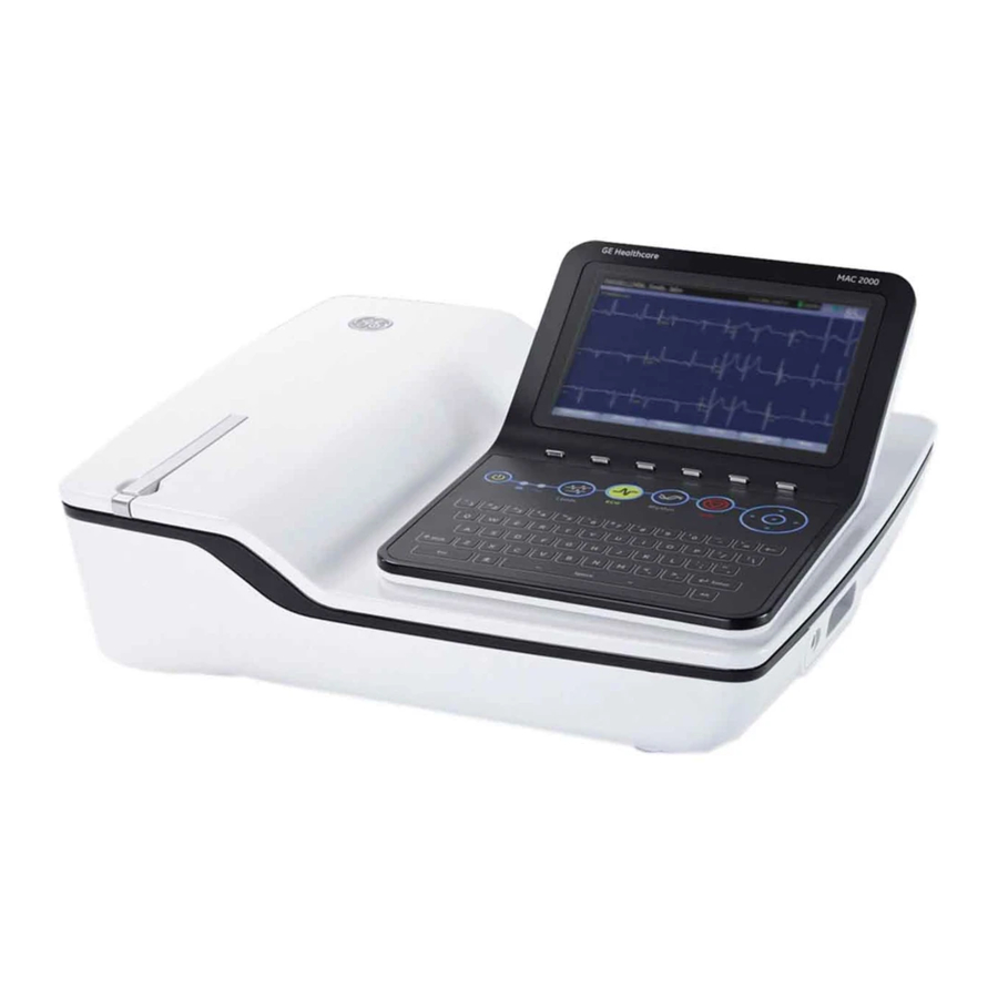
Page 34: Front View
Product Overview Front View Front View of Device Item Name Description Display Presents waveform and text data. Function Keys Selects menu options on the screen. Keypad Use to select menu options on the screen. Printer door push button Opens the printer door. Prints reports. -
Page 35: Side View
Product Overview Rear View of Device (cont'd.) Item Name Description USB ports (2) Standard Universal Serial Bus (USB) connector for USB devices, such as the optional barcode reader, optional USB WiFi Dongle, or an external non-multimedia USB keyboard. COMM A port Serial connector for data communication with CASE/CardioSoft or MUSE systems. -
Page 36: Internal View
Product Overview Internal View Internal View of Device Item Description Printer Battery compartment Printed Wiring Assembly (PWA) KISS connector port ECG patient cable connector port SD Card port RJ45 LAN connection port USB ports (2) COMM A port COMM B port RJ11 Phone port to Internal Modem Power Supply 2053535-003C... -
Page 37: Keypads
Product Overview Keypads Standard Keypod Item Name Description Power on/off Turns the system on or off. Battery LED Indicates various battery states: • Steady amber indicates the battery is charging • Flashing amber indicates the battery is low • No light indicates the battery is neither charging nor low Power LED ON indicates the device is plugged in and receiving... - Page 38 Product Overview Item Name Description Function keys Use to select menu options on the screen. NOTE: There is no marking on the keypad for the function keys. Up to six menu options may be available at any given time, and each option corresponds to a function key directly below the display.
- Page 39 Product Overview Item Name Description Item Name Description Stress keys Controls stress equipment connected to the system. Stress Keys Stress Keys Item Name Description Pretest stress key Selects the pretest phase or advances to the next stage within the phase. Exercise stress key Selects the exercise phase or advances to the next stage within the phase...
-
Page 40: Architecture And Theory Of Operation
Product Overview Architecture and Theory of Operation This section describes the block diagram, hardware/firmware architecture, and the product interfaces for this system. Block Diagram The following diagram illustrates the basic layout of this system. 2053535-003C MAC™ 2000 ECG Analysis System... - Page 41 Product Overview 2053535-003C MAC™ 2000 ECG Analysis System...
-
Page 42: Hardware/Firmware Architecture
Product Overview Hardware/Firmware Architecture This system includes the following subsystems: • PWA main board The main board has a main CPU in which the application software runs. All of the peripherals, such as the display, internal modem, LAN, serial ports, USB ports, and SD card are interfaced and controlled by this CPU. -
Page 43: Service Setup
Service Setup The diagnostic tests verify that the system operates properly. Run the diagnostic tests to check the operation of the display screen, speaker, keypad, thermal writer, battery, and communications. These diagnostic tests are useful tools for troubleshooting problems, and can be useful as part of system checkout procedures. Accessing Service Setup Use the following procedure to access Service Setup. -
Page 44: Device Settings
Service Setup The Service Setup menu opens. Use the Trimpad to highlight the button you want and press Enter. Device Settings Use the following procedure to enter your device settings. On the Service Setup menu, select Device Settings and press Enter. The following window opens: In the Serial Number field, type the serial number of the device. -
Page 45: Setting Up Event Logging
Service Setup Setting Up Event Logging Use the following procedure to set up Event Logging. On the Service Setup menu, highlight Event Log and press Enter. The following window opens: Enable or disable event logging. • To enable event logging, select the Key Event Logging check box. •... -
Page 46: Exporting The Event Log
To access the log file, insert the SD card into an SD card reader that is connected to a computer with a Windows operating system and a text editor such as Notepad or WordPad. If GE Healthcare technical service requests the Event Log for troubleshooting an issue, send the file as an email attachment. -
Page 47: Testing The Display
Service Setup The DIAGNOSTIC TESTS window opens. The following sections describe how to perform the specific diagnostic tests. Proceed to the appropriate section for the test you need to perform. Testing the Display Use the Display Test to determine if the display pixels are working properly. Open the DIAGNOSTIC TESTS window as described in “System Diagnostics”... - Page 48 Service Setup Select Start Test. The following window opens. Press the right arrow on the Trimpad repeatedly to move the color bars horizontally across the screen. Verify that the color band pattern (red, green, blue, white) scrolls across the screen. Pass the test if the pattern is replicated without discoloration.
-
Page 49: Testing The Speaker
Service Setup Press Esc or Enter when the test is done. The following window opens. Select pass or fail: • If the test passed, press Yes. • If the test failed, press No. Check the connection (cable) between the display and PWA to ensure it is connected properly and intact. -
Page 50: Testing The Keypad
Service Setup Testing the Keypad Use the Keyboard Test to determine if the keypad is working properly. Open the Diagnostic Tests window as described in “System Diagnostics” on page Select Keyboard Test. The following window opens. Press each key on the keypad and verify that two asterisks (**) appear in the corresponding representation of that key on the screen. -
Page 51: Testing The Acquisition Module
Service Setup Testing the Acquisition Module Use the Acquisition Module Test to determine if the acquisition board is working properly. Open the Diagnostic Tests window as described in “System Diagnostics” on page Select Acquisition Module Test. A window similar to the one shown in the following screen opens. NOTE: The version displayed depends on the software installed. -
Page 52: Testing The Writer
Service Setup Status Description Battery Life Remaining The estimated time remaining based on the present current draw. Because no printing is occurring during this status check, this time is calculated based on using the system for display purposes only. Actual remaining battery life is less when using the system for both display and printing purposes. - Page 53 Service Setup Perform the 50mm/s Speed Test. Select 50mm/s Speed Test. The writer prints the 50 mm/s speed test report. When one page of the report has printed, press Stop. The following window opens. Examine the printed report. Use the following criteria to determine if the writer passed or failed the 50mm/s speed test.
- Page 54 Service Setup If one cycle of the square wave spans 12.5 mm on paper, measured from corner to corner of the wave, with an allowable tolerance of 0.5 ±1.25 mm (10%), the test passes. If this criteria is not met, the test fails. •...
-
Page 55: Communications Tests
Service Setup Steps for Writer Test Failure (cont'd.) Observed Failure Remedy Faded prints Faulty printhead Clean the printhead. “Cleaning the Printhead” on page Faulty roller Replace the roller in the printer door assembly. “Printer Door” on page 103. Printhead pressure problem Replace the springs and printhead holder. - Page 56 Service Setup • Modem (internal) • USB port Use the procedures in the following sections to conduct the necessary tests. Testing the COM (RS232) Ports Use the RS232 Test to determine if the COM ports are working properly. Open the Diagnostic Tests window as described in “System Diagnostics”...
- Page 57 Service Setup In the case of wireless (WiFi) LAN, ensure that the wireless LAN settings are configured as explained in Communication Setup in the MAC™ 2000 ECG Analysis System Operator’s Manual. Open the Diagnostic Tests window as described in “System Diagnostics” on page Select LAN Test.
- Page 58 Service Setup Then the results of the test are displayed. • The test passes if the following message is displayed in the window: Passed. • The test fails if the following message is displayed in the window: Failed. If the Internal Modem Test fails, do the following: Replace the internal modem as described in “Replacing the Internal Modem”...
-
Page 59: Testing The Patient Leadwires
Service Setup When the test is done, press Esc or Cancel. The following window opens: Do one of the following, depending on the results of the test: • If the test passed, press Yes • If the test failed, press No. Replace the main PWA as described in “PWA”... -
Page 60: Printing A Service Report
Service Setup Replace every leadwire that failed the test. Repeat the test. If the leadwire still fails the test, replace the main PWA as described in “PWA” on page 120. Printing a Service Report Use the following procedure to print a service report after completing any of the diagnostic tests. - Page 61 Service Setup Press More > More > Service Setup. A window opens prompting you to enter the Service password. Type prod and press OK. NOTE: If the keypad does not include the letters prod, type 7763 and press OK. The Service Setup menu opens. Use the trimpad to highlight Software Update and press Enter.
- Page 62 Service Setup Updating the OS Use the following procedure to update the OS. Click OS Update. • If you try to update the OS without having AC power connected (you are running on battery power), the system displays the following message: 2053535-003C MAC™...
- Page 63 Service Setup Connect the AC power cord before continuing. • If an SD card is not present, the system displays the following message: Insert the SD card and click OK (on the tab at the bottom of the window). After you click OK, or if the SD card is already present, the following message is displayed: Click Yes to proceed to updating the software.
- Page 64 Service Setup Click OK (on the tab at the bottom of the screen). The date and time freeze and the following message is flashed on the screen: • If the update is not successful, corresponding messages are displayed. Check the files on the SD card. •...
- Page 65 Service Setup Updating the Acquisition Firmware Use the following procedure to update the Acquisition Firmware. Click Acquisition FW Update. The following window opens displaying the firmware version on the device and SD card: Press Enter to update the firmware. While the update is in progress, the following message is displayed: 2053535-003C MAC™...
- Page 66 Service Setup Press Enter to select the OK button. The following message is displayed: • If the update fails, corresponding messages are displayed. The following message is an example: Press OK to return to the update screens. Check the files in the SD card. •...
- Page 67 Service Setup Updating the PSOC Firmware Use the following procedure to update the PSOC firmware. Click on PSOC FW Update. 2053535-003C MAC™ 2000 ECG Analysis System...
-
Page 68: Formating The Flash Memory
Service Setup The following window opens displaying the firmware version on the device and SD card: Press Enter to update the firmware. While the update is in progress, the following message is displayed: Press Enter to select the OK button. The following message is displayed: •... - Page 69 Service Setup you should confirm that any memory or data corruption issues are not the result of a change in the device’s configurations or settings. Use the following procedure to format the device’s flash memory. WARNING: DATA LOSS — Formatting the device’s internal flash drive erases all the data in memory and returns the device to its factory settings.
-
Page 70: Opening A Command Prompt
Service Setup After the device’s flash memory is formatted, you need to reconfigure the device, Refer to the MAC™ 2000 ECG Analysis System Operator’s Manual for information on configuring the device. If formatting the device’s memory flash does not resolve the memory or data corruption issues, you need to replace the main PWA. -
Page 71: Maintenance
“Cleaning the Printhead” on page 99. The system does not require any calibration procedures. GE Healthcare recommends that you perform electrical safety checks annually. For more information, “Electrical Safety Checks” on page 132. -
Page 72: Fru Replacement Procedures
Maintenance • Small needle-nose pliers • Large paper clip or small diameter Allen wrench • Small adjustable wrench • Multimeter • Service manual for your system • Operator’s manual for your system FRU Replacement Procedures This section describes the Field Replaceable Units (FRUs) that are part of your system. After you have finished replacing the unit, you need to conduct the functional checkout procedures for that FRU. -
Page 73: Preparing The System For Fru Replacement
Maintenance Item Description Top Cover Chassis Bottom Cover Power Supply Main PWA Display Keypad Patient Cable Internal Modem Battery Printer Assembly KISS Pump Preparing the System for FRU Replacement Prior to performing any disassembly procedures, perform the following steps: NOTE: Take strict precautions against electrostatic discharge damage while replacing field replaceable units. -
Page 74: Battery
Maintenance Remove any paper from the paper compartment. Refer to the device’s operator’s manual for more information on removing the paper from the paper compartment. Remove the battery. Follow step through step “Replacing the Battery” on page Battery Use the following procedure to replace the battery. Replacing the Battery Before beginning any steps, follow the instructions in “Preparing the System for... -
Page 75: Device Covers
Maintenance Place the new battery in the compartment and push until it clicks into place. Replace the cover on the battery compartment. It should click into place. Tighten the screw to hold the cover in place. Continue with the appropriate functional checkout procedure for this FRU. “Functional Checkout”... - Page 76 Maintenance Open the printer door and locate the latches at the top left and top right corners of the printer compartment, just below the top cover, as shown in the following photograph. Using a flat-head screwdriver, gently disengage the top cover from the latches. Gently lift the top cover part way up and detach the display cable (1) and keypad ribbon (2).
- Page 77 Maintenance Separating the Top Cover from the Top Cover Assembly Use the following procedure to separate the top cover from the top cover assembly after the top cover assembly has been removed from the device. See “Removing the Top Cover Assembly” on page 75 for instructions.
- Page 78 Maintenance Turn over the top cover, remove the two M3x5 fasteners, and lift the deco, as shown in the following photographs. Turn over the top cover and press down on the rear of the printer door release lever, as shown in the following photograph. Grasp both sides of the raised printer door release lever, as shown in the following photograph, and lift to remove it from the top cover.
- Page 79 Maintenance Replacing the Top Cover Use the following procedure to attach a new top cover to the top cover assembly after the old top cover has been removed. See “Separating the Top Cover from the Top Cover Assembly” on page 77 for removal details.
- Page 80 Maintenance Turn over the top cover and insert the O-ring into the groove on the top cover, as shown in the following photograph. Align the tabs on the display bottom cover with the slots on the device top cover, as indicated in the following photograph. Lower the display bottom cover toward the device top cover and carefully thread the display cable and keypad ribbon through the slots on the top cover.
- Page 81 Maintenance Turn over the top cover assembly and secure the display assembly to the top cover using the six fasteners shown in the following photograph. The top cover assembly, with the display assembly mounted on it, is now completely reassembled, as shown in the following photograph. Proceed to “Reattaching the Top Cover Assembly to the Device”...
- Page 82 Maintenance Line up the top cover and gently lower it until the latches snap into place at the top left and top right corners of the printer compartment, just below the top cover, as shown in the following photograph. Turn the device over so the bottom cover is facing upward and tighten the screws securing the bottom cover, as shown in the following photograph.
- Page 83 Maintenance Remove the power supply assembly. See step through step “Removing the Power Supply Assembly” on page for instructions. If it is installed, remove the KISS pump and tubing. See step through step “Removing the KISS Pump Assembly” on page 126 for instructions.
- Page 84 Maintenance Disconnect the cables and harnesses, identified in the following photograph, from the PWA. Lift the chassis from the bottom cover, carefully threading the cables through the slots in the chassis. You have now detached the chassis and PWA from the bottom cover. You can now service the printer assembly or continue to remove the bottom cover.
- Page 85 Maintenance Attaching the Chassis Use the following procedure to attach the chassis and PWA to the bottom cover. Lower the chassis onto the bottom cover, carefully threading the cables through the slots in the chassis. Connect the cables and harnesses, identified in the following photograph, to the PWA.
- Page 86 Maintenance If it was installed, replace the KISS pump and tubing. See step through step “Replacing the KISS Pump Assembly” on page 127 for instructions. Replace the power supply assembly. See step through step “Replacing the Power Supply Assembly” on page for instructions.
- Page 87 Maintenance Lift the power supply/KISS pump base from the chassis. Disconnect the cables and harnesses, identified in the following photograph, from the PWA. Remove the PWA. “PWA” on page 120 for more information. Lift the chassis from the bottom cover, carefully threading the cables through the slots in the chassis.
- Page 88 Maintenance Connect the cables and harnesses, identified in the following photograph, to the PWA. Position the power supply/KISS pump base on the chassis. Secure the power supply/KISS pump base to the chassis using its fasteners, as identified in the following photograph. If it was installed, replace the KISS pump and tubing.
- Page 89 Maintenance Bottom Cover The following procedures describe how to remove and replace the bottom cover. Removing the Bottom Cover Use the following procedure to remove the bottom cover. Before beginning any steps, follow the instructions in “Preparing the System for FRU Replacement”...
- Page 90 Maintenance Replacing the Bottom Cover Use the following procedure to replace the bottom cover. Insert the side and rear paper spacers in the bottom cover and secure with four M3x5 fasteners, as shown in the following photograph. Replace the power inlet module. See step through step “Replacing the Power Inlet Module”...
-
Page 91: Power Supply
Maintenance Power Supply The following procedures describe how to remove and replace the power supply. Removing the Power Supply Assembly Use the following procedure to remove the power supply assembly. Before beginning any steps, follow the instructions in “Preparing the System for FRU Replacement”... -
Page 92: Power Inlet Module
Maintenance Replacing the Power Supply Assembly Use the following procedure to replace the power supply. Position the new power supply assembly onto the power supply base. Insert the four (4) screws to secure the power supply assembly to its base, as shown in the following photograph. - Page 93 Maintenance Removing the Power Inlet Module Use the following procedure to remove the power inlet module. Before beginning any steps, follow the instructions in “Preparing the System for FRU Replacement” on page Remove the top cover assembly, if it is has not been removed already. “Removing the Top Cover Assembly”...
-
Page 94: Printer
Maintenance Printer The following procedures describe how to replace the printer module assembly, the printer motor and gear assembly, the paper sensor, the print head, the printer door, and the printer door sensor. Printer Module Assembly The following procedures describe how to remove and replace the printer module assembly. - Page 95 Maintenance Replacing the Printer Module Assembly Use the following procedure to replace the printer module assembly. Insert the new printer module assembly into the bottom cover and snap it into place. Ensure the screw holes in the printer module assembly line up properly with the screw holes in the bottom cover.
- Page 96 Maintenance Holding the printer module assembly vertically, remove the fastener securing the printer motor cover to the printer module assembly, as shown in the following photograph, and lift off the printer motor cover. Remove the two fasteners securing the printer motor to the printer module assembly, as shown in the following photograph, and lift off the printer motor.
- Page 97 Maintenance Position the printer motor on the printer module assembly and secure with the two fasteners, as shown in the following photograph. Position the printer motor cover over the printer motor and secure with its fastener, as shown in the following photograph. Reattach the printer module assembly to the bottom cover.
- Page 98 Maintenance Remove the printer motor and gear assembly. “Removing the Printer Motor and Gear Assembly” on page 95 for instructions. Remove the two fasteners on each end of the printer module assembly, as shown in the following photographs. Holding each end of the printer module assembly, gently push out the end pieces and use your middle fingers to slide the crossbar toward you, as shown in the following photograph.
- Page 99 Maintenance Holding each end of the printer module assembly, gently push out the end pieces and use your thumbs to slide the crossbar into position, as shown in the following photograph. Snap the two end pieces back into place and secure them to the printer module assembly with two fasteners on each end, as shown in the following photographs.
- Page 100 NOTE: Use only original GE Healthcare writer paper. This paper has a special coating that prevents electrostatic buildup and contamination and debris collection on the printhead. Using other paper may result in recordings of poor quality. Use of other papers may wear out the printhead prematurely and may void the warranty.
- Page 101 Maintenance With the rear of the printer module assembly facing you, remove the two M3x4 fasteners securing the print head to the printer module assembly, as identified in the following photograph. To remove the print head, gently lift it from the metallic print head holder, as shown in the following photograph, and carefully thread the two printer ribbon cables through the printer module assembly casing.
- Page 102 Maintenance Replacing the Printhead Use the following procedure to replace the print head in the printer module assembly. Hold the new print head so the longer ribbon cable is on the right, as shown in the following photograph. With the front of the printer module assembly facing you, gently thread the printer ribbon cables through the printer module assembly and snap the print head into the metallic print head holder, as shown in the following photograph.
- Page 103 Maintenance Printer Door The following procedures describe how to remove and replace the printer door. Removing the Printer Door Use the following procedure to remove the printer door. Before beginning any steps, follow the instructions in “Preparing the System for FRU Replacement”...
- Page 104 Maintenance Gently pull the door hinge to the position shown in the following photograph. Remove the spring shown in the following photograph. Remove the printer door. 2053535-003C MAC™ 2000 ECG Analysis System...
- Page 105 Maintenance Replacing the Printer Door Use the following procedure to replace the printer door. Slide the new printer door into place. Attach the spring shown in the following photograph. Slide the door hinge into the position shown in the following photograph. Insert the dampers on the either side of the printer door, as shown in the following photograph.
- Page 106 Maintenance Turn the bottom cover over and replace and tighten the four screws securing the printer door to the bottom cover, as shown in the following photograph. Reattach the printer module assembly. See step through step “Replacing the Printer Module Assembly” on page for instructions.
- Page 107 Maintenance Holding the printer module assembly vertically, remove the fastener securing the printer motor cover to the printer module assembly, as shown in the following photograph, and lift off the printer motor cover. Locate the printer door sensor, as identified in the following photograph. With a pair of needle nose pliers, gently remove the snap-fitted cover securing the printer door sensor to the printer module assembly, as shown in the following photograph.
-
Page 108: Display Assembly
Maintenance Replacing the Printer Door Sensor Use the following procedure to replace the printer door sensor on the printer module assembly. Snap the printer door sensor into the printer door sensor cover, as shown in the following photograph. With a pair of needle nose pliers, gently snap the printer door sensor cover into place on the printer module assembly, as shown in the following photograph. - Page 109 Maintenance Removing the Display Assembly Use the following procedure to remove the display assembly. Before beginning any steps, follow the instructions in “Preparing the System for FRU Replacement” on page Remove the top cover assembly. “Removing the Top Cover Assembly” on page 75 for instructions.
- Page 110 Maintenance Remove the ten screws from the display bottom cover, as identified in the following photograph. Remove the display bottom cover, carefully threading the display cable and keypad ribbon through the openings. Disconnect the display cable and remove it from the LCD display. NOTE: The ferrite on the display cable is affixed to the display with a double-sided tape which can be gently removed.
- Page 111 Maintenance Replacing the Display Assembly Use the following procedure to replace the display assembly. Insert the new display module into the display bezel. Replace and tighten the screws securing the display to the display holder, as shown in the following photograph. Reconnect the display cable to the LCD display and affix the cable to the back of the display, as shown in the following photograph.
- Page 112 Maintenance Insert the O-Ring into the groove on the top cover, as shown in the following photograph. Align the tabs on the display bottom cover with the slots on the device top cover, as indicated in the following photograph. Lower the display bottom cover to the device top cover and carefully thread the display cable and keypad ribbon through the slots on the top cover.
-
Page 113: Keypad
Maintenance The top cover assembly, with the display assembly mounted on it, is now completely reassembled, as shown in the following photograph. Reattach the top cover assembly. “Reattaching the Top Cover Assembly to the Device” on page 81 instructions. Continue with the appropriate functional checkout procedure for this FRU. “Functional Checkout”... - Page 114 Maintenance Turn over the top cover assembly, slide the display assembly toward the front of the top cover assembly, and lift the display assembly, as shown in the following photograph. NOTE: Carefully guide the display cable and keypad ribbon out of the slots on the top cover.
- Page 115 Maintenance Remove the display bottom cover, carefully threading the display cable and keypad ribbon through the openings. Disconnect the display cable and remove it from the LCD display. NOTE: The ferrite on the display cable is affixed to the display with a double-sided tape which can be gently removed.
- Page 116 Maintenance Reconnect the display cable to the LCD display and affix the cable to the back of the display, as shown in the following photograph. NOTE: The ferrite on the display cable has double-sided tape that allows it to be gently affixed to the back of the display.
- Page 117 Maintenance Insert the O-Ring into the groove on the top cover, as shown in the following photograph. Align the tabs on the display bottom cover with the slots on the device top cover, as indicated in the following photograph. Lower the display bottom cover to the device top cover and carefully thread the display cable and keypad ribbon through the slots on the top cover.
-
Page 118: Internal Modem
Maintenance The top cover assembly, with the display assembly mounted on it, is now completely reassembled, as shown in the following photograph. Reattach the top cover assembly. “Reattaching the Top Cover Assembly to the Device” on page 81 instructions. Continue with the appropriate functional checkout procedure for this FRU. “Functional Checkout”... - Page 119 Maintenance Locate the internal modem on the PWA, as indicated in the following photograph. Grasping the edges of the internal modem between your thumb and fingers, gently lift the modem from the PWA, as shown in the following photograph. 2053535-003C MAC™...
-
Page 120: Pwa
Maintenance Replacing the Internal Modem Use the following procedure to replace the internal modem on the PWA. Locate the internal modem connectors on the PWA, as identified in the following photograph. Grasping the edges of the internal modem between your thumb and fingers, gently seat the internal modem into the connectors on the PWA, as shown in the following photograph. - Page 121 Maintenance Removing the PWA Replacing the PWA Each procedure is described in the following sections. Processing ECGs in Internal Storage If the device has the internal storage option, transmit any ECGs remaining in storage to your archival system and/or print them to ensure you have a printed record before you replace the PWA.
- Page 122 Maintenance Move the focus to Complete Setup and press Enter. The System Setup report prints. Save the printed setup report in a secure location. You can use the report as a reference if you need to restore the system setup manually.
- Page 123 Maintenance Remove the screws holding the PWA in place, as shown on the following photograph. Remove the M3x4 CSK screws securing the patient cable connector to the PWA, as shown in the following photograph. Remove the patient cable connector from the PWA, as shown in the following photograph.
- Page 124 Maintenance Replacing the PWA Use the following procedure to replace the PWA, as shown in the following photograph. Insert the PWA into place on the chassis. Connect the patient cable connector to the PWA and secure it using two M3x4 CSK screws, as shown in the following photograph.
- Page 125 Configure the Device Settings: On the Main Menu, press System Configuration. Press More > More > Service Setup. When prompted, enter the Service Password. If you do not know the password, contact GE Healthcare Technical Support. 2053535-003C MAC™ 2000 ECG Analysis System...
-
Page 126: Kiss Pump Assembly (Option)
Maintenance Select Device Settings. The following window opens. In the Serial Number field, type the serial number of the device. Refer to “Serial Number Format” on page 29 for information about the serial number.) Select the appropriate language from the Keyboard list. Press Save. - Page 127 Maintenance Detach the KISS pump harness, identified in the following photograph, from the PWA. Remove the fasteners securing the KISS pump assembly to its base. Lift the KISS pump assembly from its base. Replacing the KISS Pump Assembly Use the following procedure to replace the KISS pump assembly. Lower the KISS pump assembly into position on its base.
- Page 128 Maintenance Attach the KISS pump tubing to the locations identified in the following photograph. Replace the top cover. “Replacing the Top Cover” on page 79 for instructions. Continue with the appropriate functional checkout procedure for this FRU. “Functional Checkout” on page 129 for more information.
-
Page 129: Functional Checkout
Maintenance Functional Checkout This section lists the visual inspections and functional checkout procedures that must be performed whenever a FRU is replaced. All inspection and checkout procedures identified for a FRU also apply to the FRU’s internal PCBs and components. To use this section, do the following: Locate the appropriate FRU or non-FRU repair in one of the following tables: •... - Page 130 Maintenance Basic System FRU Repairs (cont'd.) FRU Description Visual Inspections Functional Checkouts 3, 7, 8 1, 2, 3, 7 Top Cover and Plastic Parts 1 7, 8 1, 2, 3, 9, 15 Door Sensor and Plastic Parts Paper Sensor 7, 8 1, 2, 3, 9, 15 7, 8 1, 2, 3, 9, 15...
-
Page 131: Visual Inspections
Maintenance Visual Inspections Perform the appropriate visual inspections for the repair procedure performed. Inspect the patient cable, leadwires, and electrodes. “Visual Inspection” on page 137 for more information. Discuss electrode placement, skin preparation, and patient-related requirements with the ECG technician. Verify the customer is following the recommended procedures. - Page 132 Maintenance Refer to Chapter 10, Stress Testing, in the MAC™ 2000 ECG Analysis System Operator’s Manual for more information. Diagnostic Checks 7. Conduct the display test and verify the test was passed successfully. “Testing the Display” on page 47 for more information. 8.
- Page 133 Maintenance Electrical Safety Checklist Leakage Step Test Condition UUT — ON Result Current Limits Earth Leakage Current 1 Forward Polarity ______ uA 500 uA Pass/Fail 2 Neutral open, Forward Polarity ______ uA 1,000 uA Pass/Fail 3 Neutral open, Reverse Polarity ______ uA 1,000 uA Pass/Fail...
- Page 134 Maintenance 2053535-003C MAC™ 2000 ECG Analysis System...
-
Page 135: Troubleshooting
Troubleshooting This chapter provides guidelines for troubleshooting issues with the device. It provides the following sections: • ECG Data Noise • General Fault Isolation • Power-up Self Test • Visual Inspection • Event Logging • Diagnostic Tests • Error Codes ECG Data Noise Several factors can result in unacceptable noise levels on ECGs. -
Page 136: General Fault Isolation
Troubleshooting Do the following: • Check for defective, broken, or disconnected leadwires. • Run the Patient Leadwire diagnostic test to verify that each leadwire is functioning properly. See “Testing the Patient Leadwires” on page 59 for more information. • Check for defective or expired electrodes. Additionally, you can use the Hookup Advisor to monitor ECG signal quality. -
Page 137: Visual Inspection
Troubleshooting If the equipment is not working properly, consider the following: • Is the device turned on? • Have there been any changes in the use, location, or environment of the equipment that could cause the failure? • Has the equipment hardware or software been modified since the last use? •... -
Page 138: Event Logging
Troubleshooting Visual Inspection Checklist (cont'd.) Area Look for the following problems Fasteners Loose or missing screws or other hardware, especially fasteners used as connections to ground planes on PCBs Power source • Faulty wiring, especially AC outlet • Circuit not dedicated to system NOTE: Power source problems can cause static discharge, resetting problems, and noise. - Page 139 Troubleshooting Where multiple solutions are suggested, perform the suggested actions in the order given. Once a solution restores functionality, do not attempt the next solution in the list. Acquisition Error Codes Error Code Cause Solution Check the cables and replace if necessary. Acquisition buffer overflow Replace the main PWA.
- Page 140 Troubleshooting Printer Internal Error Codes (cont'd.) Error Code Cause Solution Check the cables and replace if necessary. Printer driver timeout error Replace the main PWA. Printer driver miscellaneous Check the cables and replace if necessary. error Replace the main PWA. Undefined printer status was Check the cables and replace if necessary.
-
Page 141: Parts List
FRUs, and FRU kits considered field serviceable. Only items, assemblies, and kits that have part numbers given in this chapter are available for purchase as FRUs. To order parts, contact GE Healthcare Service Parts. - Page 142 Parts List Parts Included In GE Part FRU Description Callout Description of Parts Number 2073012-001 Card — Secure Digital (SD) 4 GB SDHC Card Battery 2066261-013 Battery (Lithium Ion) — with label MAC2000 Battery Cover — MAC2000 2066261-016 Cover Top and Plastic Parts — 1 2053535-003C MAC™...
- Page 143 Parts List Parts Included In GE Part FRU Description Callout Description of Parts Number See Note 1 at MAC2000 Keypad — Stress or Keypad Stress or (Non-Stress) the bottom of Non—Stress the table. (Illustration is Non-stress keypad) 2066261-015 Display Overlay — MAC2000 Display Overlay &...
- Page 144 Parts List Parts Included In GE Part FRU Description Callout Description of Parts Number 2066261-007 Keyboard Support Part Display Plastic Parts 1 2066261-007 Display Cover-Bottom Display Plastic Parts 1 NOTE: Select the required language and type of keypad (stress or non-stress) required for your installation.
- Page 145 GE Part FRU Description Callout Description of Parts Number 2066261-005 Cover Top, Color Chassis, Hardware Cover Top MAC 2000 2066261-016 Cover Top and Plastic Parts – 1 2066261-005 Cover Top, Color Chassis, Hardware Spring Piano Button 2066261-016 Cover Top and Plastic Parts – 1...
- Page 146 Parts List Parts Included In Callout Description of Parts GE Part FRU Description Number KISS Pump 2066261-021 Kiss Pump Assy — MAC2000 HRN Kiss Pump MAC2000 2066261-010 Harness/Cables KISS Pump 2066261-021 Connector Luer Female KISS Pump 2066261-021 Nut Lock KISS Pump...
- Page 147 Parts List Parts Included In Callout Description of Parts FRU Description GE Part Number 2066261-005 Color Chassis Cover Top, Color Chassis, Hardware PCB MAC2000 Main PWA 2066261-006 2066261-016 Holder Patient Cable Connector Cover Top and Plastic Parts – 1 2066261-005...
- Page 148 Parts List Parts Included In Callout Description of Parts GE Part FRU Description Number Harness — PS to PWA 2066261-010 Harness/Cables 2066261-010 Harness — PS Ground to PWA Harness/Cables Ground Parts Included In FRU Description GE Part Callout Description of Parts...
- Page 149 Parts List Parts Included In GE Part FRU Description Callout Description of Parts Number 2066261-011 Spring — Printer Module Hardware 3 and Power in Module Paper Sensor 2066261-018 Paper Sensor Assembly Cross Bar Paper Sensor 2066261-018 2066261-019 Print Head Assembly...
- Page 150 Parts List Parts Included In FRU Description GE Part Callout Description of Parts Number Printer Door Printer Door 2066261-004 2066261-004 Door Stiffener Printer Door 2066261-004 Printer Door Screw DIN7985 — M3x8 — 2066261-005 Cover Top, Color Chassis, Hardware 4.8-Z-A2F (ISO7045)
- Page 151 Parts List Parts Included In GE Part Callout Description of Parts FRU Description Number Cover Bottom — MAC2000 Cover Bottom 2066261-001 Cover Bottom 2066261-001 Damper Assembly 2066261-004 Printer Door Printer Door Spring — Torsion Printer Door 2066261-004 Cover Top, Color Chassis, Hardware 2066261-005 Bumpon SJ —6125, 15.9MM DIA,...
-
Page 152: Fru Lists
Parts List Parts Included In GE Part Callout Description of Parts FRU Description Number Power in Module Holder Hardware 3 and Power in Module 2066261-011 Cover Top, Color Chassis, Hardware 2066261-005 Screw CSK DIN965 M3X8 — Hardware 1 2066261-009 4.8-Z-AZF (ISO7046) -
Page 153: Cover Top, Color Chassis, Hardware (2066261-005)
Bumpon SJ-6125, 15.9 mm Diameter, 6.35 mm H Cover Top — MAC2000 Cover Top — Deco Push Button Assembly (with Pin) Push Button — Plunger GE Logo — New Push Button Spring Main PWA (2066261-006) Description Qty. PCB — MAC2000... -
Page 154: Hardware - 1 (2066261-009)
Parts List For the languages available for non-stress keypads, see “Keypads, Non-Stress” on page 157. Description Display Cover — Top Keyboard Support — Part Screw DIN7985-4.8-Z-A2F (ISO7045) Display Overlay — MAC2000 O-Ring MAC2000 Keypad Flex Tail Insulation Hardware — 1 (2066261-009) Description Qty. -
Page 155: Hardware 3 And Power-In Module (2066261-011)
Parts List Hardware 3 and Power-In Module (2066261-011) Description Qty. Harness — PIM to PS/PWA Power-in Module Holder Screw CSK DIN965 M3X8-4.8-Z-AZF (ISO7046) Roller Holder Print Head Holder Print Head Screw DIN7985-M3X4-4.8-Z-A2F (ISO7045) Printer Hinge Rod Spring — Printer Module O-Ring —... -
Page 156: Cover Top And Plastic Parts - 1 (2066261-016)
Battery Cover — MAC2000 Back Panel Cover Top — MAC2000 Cover Top — Deco Push Button Assembly (with Pin) Push Button — Plunger GE Logo — New Push Button Spring Door Sensor and Plastic Parts — Printer/Paper Tray (2066261-017) Description Qty. -
Page 157: Static Brush (2066261-020)
Parts List Static Brush (2066261-020) Description Qty. ESD Static Brush KISS Pump (2066261-021) Description Qty. KISS Pump Assembly — MAC2000 Connector Luer Female Nut Lock Plug Luer Male Harness — KISS Pump MAC2000 Internal Modem (2066261-022) Description Modem Socket MT9234SMI-HV–92.R1 Keypads, Non-Stress The following languages are available for non-stress keypads. -
Page 158: Keypads, Stress
Parts List Language Part Number 2066261-039 Korean 206626-040 Finnish Keypads, Stress The following languages are available for stress keypads. Language Part Number 2066261-041 English 2066261-042 German 2066261-043 French 2066261-044 Spanish 2066261-045 Swedish 2066261-046 Italian 2066261-047 Japanese 2066261-048 Dutch 2066261-049 Norwegian 2066261-050 Danish 2066261-051... -
Page 159: Power Supply Cords
Parts List Language Part Number 2035979-008 Dutch 2035979-009 Norwegian 2035979-010 Danish 2035979-011 Czech 2035979-013 Chinese 2035979-014 Hungarian 2035979-015 Polish 2035979-016 Russian 2035979-017 Slovene 2035979-018 Portuguese 2035979-019 Korean 2035979-020 Finnish Power Supply Cords Part Number Description 405535-006 RA HOSP GRND 13A 125V 10FT 405535-001 RA CONT EURO 10A 250V 2.5M 405535-002... - Page 160 Parts List 2053535-003C MAC™ 2000 ECG Analysis System...
-
Page 161: Related Documents
MAC™2000 ECG Analysis System Quick Reference Guide 2036070-006 Marquette™ 12SL™ ECG Analysis Program Physician’s Guide 2025762–163 GE Cardiology Open XML Reference Manual 2020299–025 LAN Option Installation and Troubleshooting Guide Documents Available in Other Languages The MAC™2000 ECG Analysis System Operator’s Manual is available in the following languages. - Page 162 Related Documents MAC™2000 ECG Analysis System Operator Manuals (cont'd.) Language Part Number 2053535-007 Croatian 2053535-008 Czechoslovakian 2053535-009 Danish 2053535-010 Dutch 2053535-002 English 2053535-011 Estonian 2053535-012 Finnish 2053535-013 French 2053535-014 German 2053535-015 Greek 2053535-016 Hungarian 2053535-017 Indonesian 2053535-018 Italian 2053535-019 Japanese 2053535-020 Korean 2053535-021...
- Page 163 Related Documents MAC™2000 ECG Analysis System Operator Manuals (cont'd.) Language Part Number 2053535-033 Turkish 2053535-034 Ukrainian The MAC™2000 ECG Analysis System Supplies and Accessories Reference Guide is available in the following languages. MAC™2000 ECG Analysis System Supplies and Accessories Reference Guides Language Part Number 2053535-035...
- Page 164 Related Documents MAC™2000 ECG Analysis System Supplies and Accessories Reference Guides (cont'd.) Language Part Number 2053535-062 Swedish 2053535-063 Turkish 2053535-064 Ukranian 2053535-003C MAC™ 2000 ECG Analysis System...
-
Page 165: Electromagnetic Compatibility (Emc)
Electromagnetic Compatibility (EMC) This section describes the EMC information relevant to your product. Changes or modifications to this system not expressly approved by GE Healthcare could cause EMC issues with this or other equipment. This system is designed and tested to comply with applicable regulations regarding EMC, and must be installed and put into service according to the EMC information stated in this section. -
Page 166: Guidance And Manufacturer's Declaration-Electromagnetic Immunity
Electromagnetic Compatibility (EMC) EMC Emissions Test Emissions Test Compliance Electromagnetic Environment–Guidance Group 1 RF emissions (Radiated) This device uses RF energy only for its internal function. Class B • CISPR11:2003/A1:2004/ Therefore, its RF emissions A2:2006 are very low and are not likely •... -
Page 167: Guidance And Manufacturer's Declaration-Electromagnetic Immunity
Electromagnetic Compatibility (EMC) EMC Immunity Test Immunity Test Compliance Electromagnetic Environment–Guidance Electrostatic discharge (ESD) Floors should be wood, ± 2/4/6 kV indirect concrete, or ceramic tile. ± 2/4/6 kV direct • IEC 60601-1-2:2007 If the floors are covered ± 2/4/8 kV air •... - Page 168 Electromagnetic Compatibility (EMC) EMC Immunity Test Immunity Test Compliance Compliance Electromagnetic Test Level Level Environment–Guidance Do not use portable or mobile RF communications equipment closer to any part of the system, including the cables, than the recommended separation distance calculated for the equation applicable to the frequency of the transmitter.
- Page 169 Electromagnetic Compatibility (EMC) EMC Immunity Test (cont'd.) Immunity Test Compliance Compliance Electromagnetic Test Level Level Environment–Guidance Radiated RF 3 V/m Multilink Lead Multilink Lead Set: 80 MHz to 2.5 set: 3.0 V/m d = 1.2 √P 80 MHz to 800 MHz d = 2.3 √P 800 MHz to 2.5 GHz Value Lead set: @ 2 Hz mod.
-
Page 170: Recommended Separation Distances
Electromagnetic Compatibility (EMC) Recommended Separation Distances The following table provides the recommended separation distances (in meters) between portable and mobile RF communication equipment and the system described in this manual, for equipment and systems that are not life-supporting. The system is intended for use in the electromagnetic environment in which radiated RF disturbances are controlled. -
Page 171: Technical Specifications
Technical Specifications System Specifications Hardware Device Item Specifications Device type Portable, integrated unit Width 390 mm (15.4 in) Depth 330 mm 13.0 in) 200 mm (7.9 in) Height Weight approx. 5 kg (11.0 lb) (including battery, without paper) CRT Interface No CRT interface connector USB Port Two USB 2.0 ports available... - Page 172 Technical Specifications Display (cont'd.) Item Specifications Data Heart rate, patient ID, clock, battery power indicator, waveforms, lead labels, speed, gain and filter settings, warning messages, prompts, and help messages. Standard display: 6 leads Optional display: 12 leads Traces 3, 6, 12 Sweep Speed 12.5, 25, and 50 mm/s Filtered ECG...
-
Page 173: Acquisition, Processing, And Performance
Technical Specifications Electrical Item Specifications Power supply Internal AC/DC or battery operation 100–240 VAC ±10% Input voltage Input current 1.5A at 115V to 230V AC (Maximum power consumption) 47–63 Hz Input frequency Safety requirement IEC60601–1 protection class I Fuse requirement Phase and neutral meet UL/IEC requirements IEC C14 type Power inlet socket... - Page 174 Technical Specifications ECG Data Acquisition (cont'd.) Item Specification Common mode rejection >135 dB with 50/60 Hz filter on >10 MΩ @ 10 Hz Input impedance Patient leakage current <10 µA normal condition (NC) <50 µA single fault condition (SFC) Remote control Advancing to the next stage can be initiated from the bicycle ergometer.
-
Page 175: Operating Modes, Features, And Options
Technical Specifications Processing (cont'd.) Item Specifications ECG transmission Resting ECGs can be transferred via the serial interface, modem, LAN, as well as SD-card from the MAC2000 system to other ECG systems (CardioSoft/CardioSys, MUSE) for further processing and archiving. In addition, Resting ECG can be received via serial line, modem, and SD Card. - Page 176 Technical Specifications Operating Modes and Features (cont'd.) Item Specifications Multi-language support User Interface supports 19 languages User Manual supports 31 languages Order Manager Provides an interface for managing orders Accessories Item Specification Consumables Electrodes, leadwires, cables, and so forth For a complete list of all available supplies and accessories for this system, refer to the MAC™...
-
Page 177: Wifi Country List
WiFi Country List This appendix identifies country-specific regulations in the use of WiFi technology in a medical environment. You should be aware of these regulations prior to setting up WiFi communications in your device. Allowable Channels The following table identifies the wireless channels that are allowed for use in a medical environment. - Page 178 WiFi Country List Region Country Allowed Channel(s) Europe Austria Belarus Belgium Cyprus Czech Denmark Estonia Finland France Germany Greece Hungary Iceland Ireland Italy Latvia Liechtenstein Lithuania Luxembourg Malta Netherlands Norway Poland Portugal Romania Russia Slovakia Slovenia Spain Sweden Switzerland Turkey Oceania Australia New Zealand...
- Page 179 Index 12ld stress key 39 related 161 alt key 38 ECG key 37 Assistance 31 Electrical Fast Transient/ burst (EFT) EMC immunity test 167 electromagnetic backspace key 38 separation distances 170 biocompatibility statement 19 electromagnetic compatibility 165 electrostatic discharge (ESD) EMC immunity test 167 classification EMC 18...
- Page 180 EMC immunity test 167 LED descriptions flicker emissions test 166 battery charging 173 front view 34 function keys 38 manufacturer responsibilities 20 GE Healthcare medians stress key 39 Common Documentation medical device Library (CDL) 2 classification 17 manuals 2 grade down key 39...
- Page 181 EMC immunity test 169 recall 39 Radio Frequency (RF) recovery 39 cautions 18 speed/load down 39 devices 18 speed/load up 39 rear view 34 start treadmill 39 recall stress key 39 stop treadmill 39 recovery stress key 39 test end 39 related documents 161 symbols requirements...
- Page 182 2053535-003C MAC™ 2000 ECG Analysis System...
- Page 184 +49 761 45 43 -233 Shanghai, People's Republic of China 201203 Fax: +1 414 355 3790 Tel: +86 21 3877 7888 Fax: +86 21 3877 7451 GE Medical Systems Information Technologies, Inc., a General Electric Company, going to market as GE Healthcare. www.gehealthcare.com 0459...
Need help?
Do you have a question about the MAC 2000 and is the answer not in the manual?
Questions and answers
I have a Mac 2000 EKG. After running a patient, the unit will not let me add another patient without fully powering down and turning back on. Could this be a battery problem or something different?
The issue with the GE MAC 2000 ECG not allowing the addition of a new patient after running one is not necessarily related to a battery problem. The troubleshooting section suggests checking for operator error, software or hardware modifications, and verifying if the device is turned on. If the device is functioning but not allowing new patient entry, it may be due to system configuration settings or software-related factors rather than a battery issue.
This answer is automatically generated
Acquisition error 9
Acquisition error 9 for the GE MAC 2000 means that the acquisition driver failed to open. The solution is to replace the main PWA (Printed Wiring Assembly).
This answer is automatically generated
my ekg is not reading properly
Dear all, I would like to ask for safety technical inspection - supposed to be every year? every two years? No need it? Can you tell me, where is specification for this information? KR, Martina Januskova
WHAT DO I REPLACE WHEN THE KEYPAD IS DAMAGED AND SOME BUTTONS ARE NOT WORKING?