GE Marquette MAC 5000 Field Service Manual
Resting ecg analysis system
Hide thumbs
Also See for Marquette MAC 5000:
- Operator's manual (229 pages) ,
- Service manual (176 pages) ,
- Operator's manual (258 pages)

Related Manuals for GE Marquette MAC 5000


Summary of Contents for GE Marquette MAC 5000
- Page 1 ® 5000 resting ECG analysis system field service manual PN 2000657-002 Revision A...
- Page 3 ® 5000 resting ECG analysis system field service manual PN 2000657-002 Revision B...
- Page 4 400, Spectra-Overview, Spectra-Tel, ST GUARD, TRAM, TRAM-NET, TRAM-RAC, TRAMSCOPE, TRIM KNOB, Trimline, UNION STATION, UNITY logo, UNITY NETWORK, Vari-X, Vari-X Cardiomatic, VariCath, VARIDEX, VAS, and Vision Care Filter are trademarks of GE Marquette Medical Systems, Inc. registered in the United States Patent and Trademark Office.
-
Page 5: Table Of Contents
Contents Introduction ..........1-1 Manual Information ..............1-3 Revision History ................. 1-3 Manual Purpose ................. 1-3 Intended Audience ................1-3 Conventions ..................1-4 Safety Information ..............1-5 Definitions ..................1-5 Messages ................... 1-5 Responsibility of the Manufacturer ............ 1-6 General ....................1-6 Equipment Symbols ................ - Page 6 Maintenance ..........3-1 Introduction ..............3-3 Recommended Maintenance .............. 3-3 Preventive Maintenance Inspection Report ........3-3 Required Tools and Supplies ............. 3-3 Inspection and Cleaning ............. 3-4 Visual Inspection ................3-4 Exterior Cleaning ................3-4 Interior Cleaning ................3-4 General ................. 3-4 Thermal Printhead ..............
- Page 7 Test #4 ..................... 3-16 Ground Continuity ................3-17 Preventive Maintenance ............3-18 Troubleshooting ........... 4-1 Assembly Descriptions ............... 4-3 Introduction ..................4-3 Assembly Block Diagram ..............4-3 Input and Output Connectors ............4-4 A Pins (J1) ..................4-4 COM1 (COM3/4) Pins (J3) ..............4-4 COM2 Pins (J5) .................
- Page 8 Writer Tests ..................4-19 C-Scan Test 1 C-Scan Test 2 C-Scan Test 3 ..............4-19 50 mm/s Test Pattern I 25 mm/s Test Pattern I 5 mm/s Test Pattern I ............4-19 Roller Test ................4-20 Test Pattern II ..............4-20 Test Pattern II Continuous ..........
- Page 9 Serial EEPROM Interface ............ 5-10 BBus Interface ..............5-10 UARTS ................5-11 PWM Analog Outputs ............5-11 Beep Generator ..............5-11 DRAM ....................5-12 SmartMedia Card ................5-12 Serial EEPROM ................5-12 VGA LCD/CRT Interface ..............5-12 Acquisition Module Transceiver/Power Switch ........ 5-12 Thermal Printhead Power/Pixel Test Logic ........
- Page 10 PCB Assemblies ..........7-1 801212-003A CPU PCB Assembly ..........3 SD801212-003A CPU ..............10 801220-001B Battery Transition PCB .......... 26 SD801220-001A Battery Transition ..........27 801222-001A LED PCB ............28 SD801222-001A LED ..............29 2001326-001A Motor Protect PCB ..........31 2001326-001A Motor Protect .............
-
Page 11: Introduction
Introduction Manual Information ..............3 Revision History ..................3 Manual Purpose ..................3 Intended Audience ................. 3 Conventions ................... 4 Safety Information ............... 5 Definitions ....................5 Messages ....................5 Responsibility of the Manufacturer ............6 General ....................6 Equipment Symbols ................7 Service Information .............. - Page 12 MAC 5000 resting ECG analysis system Revision B 2000657-002...
-
Page 13: Manual Information
Introduction: Manual Information Manual Information Revision History Each page of the document has the document part number and revision letter at the bottom of the page. The revision letter identifies the document’s update level. The revision history of this document is summarized in the table below. Table 1-1. -
Page 14: Conventions
Introduction: Manual Information Conventions Table 1-2. Styles Style Definition Black text Indicates keys on the keyboard, text to be entered, or hardware items such as buttons or switches on the equipment. Italicized text Indicates software terms that identify menu items, buttons or options in various windows. -
Page 15: Safety Information
Introduction: Safety Information Safety Information Definitions Indicates an imminently hazardous DANGER situation which, if not avoided, WILL result in death or serious injury. Indicates a potentially hazardous WARNING situation which, if not avoided, COULD result in death or serious injury. Indicates a potentially hazardous CAUTION situation which, if not avoided may result... -
Page 16: Responsibility Of The Manufacturer
Introduction: Safety Information Responsibility of the GE Marquette Medical Systems is responsible for the effects of safety, reliability, and performance only if: Manufacturer Assembly operations, extensions, readjustments, modifications, or repairs are carried out by persons authorized by Marquette. The electrical installation of the relevant room complies with the requirements of the appropriate regulations. -
Page 17: Equipment Symbols
Introduction: Safety Information Equipment Symbols The following symbols appear on the equipment. Type B equipment. Type BF equipment, external defibrillator protected. Alternating current. When illuminated, the green LED next to this symbol indicates AC power is connected. Equipotential. Charge the battery. The flashing amber LED next to this symbol indicates you must connect the system to AC power to re-charge the battery. -
Page 18: Service Information
Any unauthorized attempt to repair equipment under warranty voids that warranty. It is the user’s responsibility to report the need for service to GE Marquette Medical Systems or to one of their authorized agents. Equipment Identification Every GE Marquette Medical Systems device has a unique serial number for identification. -
Page 19: Equipment Overview
Equipment Overview General Description ..............3 Front View ....................3 Back View ....................3 Internal View ..................4 Preparation for Use ..............5 Trolley Assembly ................... 5 Connector Identification ................. 6 Paper Installation ................... 7 Controls and Indicators ................8 MAC 5000 resting ECG analysis system Revision B 2000657-002... - Page 20 MAC 5000 resting ECG analysis system Revision B 2000657-002...
-
Page 21: General Description
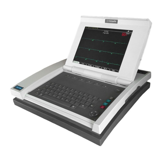
Equipment Overview: General Description General Description The MAC 5000 resting ECG analysis system is a 15 lead, 12 channel system with a 10.4 inch (264 mm) diagonal display, active patient cable, battery operation, and late potential electrocardiography. There are also options for wireless communication, vector, and network capabilities. -
Page 22: Internal View
Equipment Overview: General Description Internal View Battery Paper tray MD1325-116A MAC 5000 resting ECG analysis system Revision B 2000657-002... -
Page 23: Preparation For Use
Equipment Overview: Preparation for Use Preparation for Use Trolley Assembly 1. Mount the unit to the optional trolley by lining up the left edge of the unit to the two slots at the left edge of the trolley. MD1325-171A 2. Place the unit on the trolley surface, then slide it to the left until the tabs click and the unit is firmly in place on the trolley. -
Page 24: Connector Identification
Equipment Overview: Preparation for Use Connector Identification A B C MD1325-118A Table 2-1. Back Panel Connectors Item Name Description Not functional. Connect a Marquette KISS pump (optional). Connect a local transmission cable, serial line, Marquette KISS pump, or external modem (optional). ANA/TTL Connect a device requiring analog data or TTL trigger. -
Page 25: Paper Installation
Equipment Overview: Preparation for Use Paper Installation 1. Press the internal access button to open the unit. MD1325-092B 2. Slide a stack of paper into the writer compartment with the paper cue hole toward the internal access button. MD1325-093B 3. Pull out the top sheet of paper from the stack. MD1325-094B 4. -
Page 26: Controls And Indicators
Equipment Overview: Preparation for Use Controls and Indicators copy & rhythm " stop < > MD1325-152A Table 2-2. Keypad Item Name Description function keys Selects screen menu functions delete Erases typed characters copy Prints another ECG report Acquires an ECG rhythm Prints continuous ECG data (This data cannot be stored or transmitted.) -
Page 27: Maintenance
Maintenance Introduction ................3 Recommended Maintenance ..............3 Preventive Maintenance Inspection Report ..........3 Required Tools and Supplies ..............3 Inspection and Cleaning ..............4 Visual Inspection ................... 4 Exterior Cleaning ..................4 Interior Cleaning ..................4 General ..................4 Thermal Printhead ..............5 Battery and Patient Cable Replacement .......... - Page 28 Test #1 ....................15 Test #2 ....................15 Test #3 ....................16 Test #4 ....................16 Ground Continuity ................17 Preventive Maintenance............... 18 MAC 5000 resting ECG analysis system Revision B 2000657-002...
-
Page 29: Introduction
Preventive Maintenance To help you establish a systematic maintenance routine, GE Marquette Medical Systems recommends that, every six months, you perform the Inspection Report maintenance checks and test procedures on the “Preventive Maintenance Inspection Report,”... -
Page 30: Inspection And Cleaning
Maintenance: Inspection and Cleaning Inspection and Cleaning Visual Inspection Perform a visual inspection of all equipment and peripheral devices daily. Turn off the unit and remove power before making an inspection or cleaning the unit. Check the case and display screen for cracks or other damage. Regularly inspect all cords and cables for fraying or other damage. -
Page 31: Thermal Printhead
Maintenance: Inspection and Cleaning Thermal Printhead Clean the thermal printhead every three months or more often with heavy use. A build-up of thermal paper coating on the printhead can cause light or uneven printing. Use a solution containing alcohol on a nonwoven, nonabrasive cloth such as Techni-Cloth to wipe off the printhead. -
Page 32: Battery And Patient Cable Replacement
Maintenance: Battery and Patient Cable Replacement Battery and Patient Cable Replacement Battery Replacement 1. Press the internal access button to open the unit. 2. Slide the battery release button in the direction of the arrow and lift the battery out. MD1325-112B 3. -
Page 33: Disassembly Guidelines
Maintenance: Disassembly Guidelines Disassembly Guidelines Preliminary Steps Prior to disassembly, perform the following: If possible, process any ECGs remaining in storage. If possible, print out set-up for future reference. Disconnect the unit from the AC wall outlet and remove the power cord from the unit. -
Page 34: Reassembly
Maintenance: Disassembly Guidelines Reassembly Reassemble the power supply reversing the steps for removal. Before replacing the screws, ensure that the ground wire is routed through the notch in the plastic and not pinched. Top Cover Removal NOTE It is not necessary to remove the power supply prior to removing the top cover. -
Page 35: Reassembly
Maintenance: Disassembly Guidelines 6. Gently lift the rear of the top cover free from the unit. NOTE The top cover holds the bezel that surrounds the rear panel connectors, so the bezel may fall free at this time. 7. At the front of the top cover, gently pull the thin strip of plastic free from under the keyboard. - Page 36 Maintenance: Disassembly Guidelines 3. Press the internal access button and raise the top of the unit. Remove one screw on the inside, near the front edge of the top. Screw MD1322-004B 4. Working from the outside of the top, remove the two TORX mounting screws located on the right side of the assembly.
-
Page 37: Reassembly
Maintenance: Disassembly Guidelines Reassembly 1. Slide tabs into their mounting slots and set the display/ keyboard assembly in place. 2. Replace the two TORX mounting screws on the right side of assembly. 3. Slide the display hinge (metal rod) to the right until it snaps into the mounting detent. -
Page 38: Diskette Drive Removal/Replacement
Maintenance: Disassembly Guidelines 4. replace the top cover and power up the unit. 5. Go to the Setup menu and enter the new printhead resistance value. 6. Do a Writer Daignostics test (See 4-19). Diskette Drive Removal/ 1. Remove the top cover and display/keyboard assembly following the procedures above. -
Page 39: Domestic Electrical Safety Tests
Maintenance: Domestic Electrical Safety Tests Domestic Electrical Safety Tests AC Line Voltage Test This test verifies that the domestic wall outlet supplying power to the equipment is properly wired. For international wiring tests, refer to the internal standards agencies of that particular country. 120 VAC, 50/60 Hz Use a digital voltmeter to check the voltages of the 120-volt AC wall outlet (dedicated circuit recommended). -
Page 40: Leakage Tests
If the unit under test fails the leakage tests, do not allow the customer to use the equipment. Call Tech Support for assistance. (See the “How to Reach Us” page in the front of the manual.) GE Marquette Medical Systems recommends that you perform these tests: Before applying power for the first time... -
Page 41: Leakage Test Diagrams
Maintenance: Domestic Electrical Safety Tests Leakage Test Diagrams These diagrams show only a representation of how a typical leakage current tester functions. Follow the instructions provided with the leakage current tester that you use. Test #1 Ground-wire-leakage-to-ground “To be tested” power connector on back of tester (may not be labeled on some testers). -
Page 42: Test #3
Maintenance: Domestic Electrical Safety Tests Test #3 Patient-cable-leakage-to-ground “To be tested” power connector on back of tester (may not be labeled on some testers). Tester Tester Polarity power Norm cord power Line cord Line Neutral Unit under Neutral test (UUT) Meter Patient cable connectors... -
Page 43: Ground Continuity
Maintenance: Domestic Electrical Safety Tests Ground Continuity This test verifies that there is continuity (less than 100 mΩ resistance) between all the exposed metal surfaces, which have the potential to become energized, and the ground prong on the mains AC power cord. If the metal surfaces are anodized or painted, scrape off a small area in an inconspicuous area for the probe to make contact with the metal. -
Page 44: Preventive Maintenance
Maintenance: Preventive Maintenance Preventive Maintenance GE Marquette Medical Systems recommends that every six months you perform the maintenance checks and test procedures on the “Preventive Maintenance Inspection Report”. These maintenance procedures can be performed more often if indicated. Contact GE Marquette Service for the latest preventive maintenance procedures for this product. -
Page 45: Troubleshooting
Troubleshooting Assembly Descriptions ..............3 Introduction ................... 3 Assembly Block Diagram ............... 3 Input and Output Connectors ............4 A Pins (J1) ..................... 4 COM1 (COM3/4) Pins (J3) ..............4 COM2 Pins (J5) ..................4 ANALOG Pins (J6) ................. 5 EXT. - Page 46 50 mm/sec Test Pattern I 25 mm/sec Test Pattern I 5 mm/sec Test Pattern I ............19 Roller Test ................20 Test Pattern II & Roller Test ...........20 Continuously Run Out Paper ..........20 Communication Diagnostics ..............21 MAC 5000 resting ECG analysis system Revision B 2000657-002...
-
Page 47: Assembly Descriptions
Troubleshooting: Assembly Descriptions Assembly Descriptions Introduction The troubleshooting information in this chapter helps you narrow service problems to one of the replaceable assemblies. These assemblies, illustrated in the block diagram, are discussed in more detail in the individual assembly chapters along with replacement procedures. -
Page 48: Input And Output Connectors
Troubleshooting: Input and Output Connectors Input and Output Connectors The pin-by-pin descriptions identify the signal names and pin outs for each connector on the unit. A Pins (J1) Table 4-1. A (J1) Name Data Ground Clock MD1322-008 COM1 (COM3/4) Pins Table 4-2. -
Page 49: Analog Pins (J6)
Troubleshooting: Input and Output Connectors ANALOG Pins (J6) Table 4-4. Acquisition Module Connector (J4) Name +12V DC Output 1 TTL Trigger Output Ground Ground DC Output 2 DC Input 1 ECG Output MD1322-010 DC Input 2 EXT. VID. Pins (J7) Table 4-5. -
Page 50: Internal Cabling
Troubleshooting: Internal Cabling Internal Cabling This diagram shows the cables and connectors for the assemblies in the unit. The following pages detail the input/output signals for those connectors. W3P1 Power Input Power Supply E1 Power Supply Mounting Bracket W1E1 421117-001 700645-001 A11P1 A8P3... - Page 51 Troubleshooting: Internal Cabling Nand Card Battery Battery Pack 900770-001 CPU Board 801212-001 801220-001 RIBBON Floppy Drive 419751-001 700687-001 A1KEYBD A5P1 700657-001 Floppy Drive LCD Assy A5J1 CAM-14 421114-001 900995-001 Keyboard Assy 421115-001 MD1322-016R Revision B MAC 5000 resting ECG analysis system 2000657-002...
-
Page 52: Cpu Pcb Input/Output Signals
Troubleshooting: CPU PCB Input/Output Signals CPU PCB Input/Output Signals Battery Pack/Monitor (J2) Pin No. Signal 18V Battery Power 18V Battery Power Battery Temperature Sense 3V Temperature Sense Power Battery Ground Battery Ground LCD Backlight (J4) Pin No. Signal 12V Power 12V Power 12V Power Ground... -
Page 53: Keyboard (J8)
Troubleshooting: CPU PCB Input/Output Signals Keyboard (J8) Pin No. Signal Sense4 Sense2 Sense1 Sense0 Sense3 Sense5 Sense6 Sense7 Drive0 Drive1 Drive2 Drive3 Drive4 Ground Power Key Drive5 Drive6 Drive7 Drive8 Drive9 Drive10 Revision B MAC 5000 resting ECG analysis system 2000657-002... -
Page 54: Lcd (J10)
Troubleshooting: CPU PCB Input/Output Signals LCD (J10) Pin No. Signal Ground Pixel Clock Hsync Vsync Ground R0 (LSB) R5 (MSB) Ground G0 (LSB) G5 (MSB) Ground B0 (LSB) B5 (MSB) Ground Data Enable 3V Power 3V Power 4-10 MAC 5000 resting ECG analysis system Revision B 2000657-002... -
Page 55: Power Supply/Motor (J11)
Troubleshooting: CPU PCB Input/Output Signals Power Supply/Motor Pin No. Signal (J11) Motor Encoder B 5V Power Motor A Motor Encoder A Ground Motor B 28V Power Ground Battery Charge LED 28V Power Ground Door Open Detect Ground Revision B MAC 5000 resting ECG analysis system 4-11 2000657-002... -
Page 56: Thermal Printer (J12)
Troubleshooting: CPU PCB Input/Output Signals Thermal Printer (J12) Pin No. Signal Thermal Printer Power Thermal Printer Power Thermal Printer Power Thermal Printer Power Thermal Printer Power Thermal Printer Power Thermal Printer Power Ground Ground Ground Ground Ground Ground Ground Cue Sense 5V Main Power Ground Data Strobe... -
Page 57: Floppy Disk Drive (J13)
Troubleshooting: CPU PCB Input/Output Signals Floppy Disk Drive (J13) Pin No. Signal 5V Power Index 5V Power Drive Select 0 5V Power Disk Change Media Sense 0 Media Sense 1 Motor Select 0 Direction Step Ground Write Data Ground Write Gate Ground Track 0 Ground... -
Page 58: General Fault Isolation
Troubleshooting: General Fault Isolation General Fault Isolation Visual Inspection A thorough visual inspection of the equipment can save time. Small things—disconnected cables, foreign debris on circuit boards, missing hardware, loose components—can frequently cause symptoms and equipment failures that may appear to be unrelated and difficult to track. -
Page 59: Power-Up Flow Chart
Troubleshooting: General Fault Isolation Power-up Flow Chart Refer to the CPU PCB schematic diagram found in the PCB Assemblies chapter at the end of the manual. StrongArm access "MOE" releases SmartMedia card Press ON key nSysResest via FPGA and Sh8 pin 10 loads remaining code to DRAM Micro-Controller... -
Page 60: Diagnostic Tests
Troubleshooting: Diagnostic Tests Diagnostic Tests Introduction Verify that the MAC 5000 resting ECG analysis system operates properly by running the diagnostic tests. These tests check the operation of the display screen, speaker, keyboard, thermal writer, battery, and communication. Detailed information displays on screen. Loading the System 1. -
Page 61: System Diagnostics Main Menu
Troubleshooting: Diagnostic Tests This process only works once, so you should reprogram the password permanently. 4. Go to the Basic System menu. 5. Select Miscellaneous Setup. 6. Select the System password line and type the new password in the space. 7. -
Page 62: Anti-Aliasing Test Pattern
Troubleshooting: Diagnostic Tests The second test pattern shows 32 color levels. Check for problems with the overall pattern. (If the system does not have the color option, various grey scale patterns display.) Press the enter key to exit the test. Anti-Aliasing Test Pattern This test pattern consists of a large square with a series of lines projecting from the center of the square to the perimeter of the square. -
Page 63: Writer Tests
Troubleshooting: Diagnostic Tests Writer Tests Run the writer tests to check the motor speed control, paper speed, paper tracking, paper cueing, and print head quality. During the tests, make the following general checks. The first character printed should not be distorted. This checks start-up speed. -
Page 64: Roller Test
Troubleshooting: Diagnostic Tests Roller Test (Uneven darkness can appear if AC power is on during this test.) After cueing, printing should start at approximately 13–14 mm on the page. The pattern appears as diagonal light and dark wavy bands. MD1322-013 Isolated light spots indicate a flat spot on the roller. -
Page 65: Battery Discharge Test
Troubleshooting: Diagnostic Tests Battery current Battery temperature Maximum and minimum battery temperature Ambient temperature Maximum and minimum ambient temperature Current battery charging status Battery Discharge Test This test charges the battery to full capacity, if necessary, then monitors a discharge cycle. Monitored information, written to the floppy disk, includes: Discharge rate (in mAH) Battery temperature... -
Page 66: Modem Test
Troubleshooting: Diagnostic Tests Modem Test Connect a modem to COM 2 and select the test. The test returns the modem ID number, firmware rev, and current parameter settings. If communication with the modem is unsuccessful, the ID and firmware rev display N/A. Acq. -
Page 67: Cpu Theory Of Operation
CPU Theory of Operation General Description ..............3 Block Diagram ..................4 Theory of Operation ..............6 Clocks ....................6 CPU ......................6 FPGA ...................... 6 Bootstrap Instruction Unpacker ..........7 EDO DRAM Controller ..............7 XBus Controller ................7 LCD Controller VLB Bus Cycle Interface ........7 Video Waveform Scrolling ............8 Interrupt Controller ..............9 System Interrupt Generator ............9... - Page 68 MAC 5000 resting ECG analysis system Revision B 2000657-002...
-
Page 69: General Description
CPU Theory of Operation: General Description General Description The MAC 5000 CPU PCB contains all of the circuitry for the MAC 5000 resting ECG analysis system except for the power supply, acquisition module, keyboard and display. The board contains the following: Clocks StrongARM CPU (SA-110) FPGA for System Logic Containing:... -
Page 70: Block Diagram
CPU Theory of Operation: General Description Block Diagram See Chapter 7, “PCB Assemblies” for references on the CPU schematic. ARM Address Bus TRONG FPGA DRAM Controller DRAM Address Bootstrap (Sh2) Unloader SA-110 TRONG RA0-9 BBUS (Sh2) 4 MEG Analog DRAM (Sh2) Audio Acq Module... - Page 71 CPU Theory of Operation: General Description Controllers To Super I/O 68HC705 "Larry" Motor (Sh6) Drive "Shemp" Keyboard Sense (Sh4) Top Up Power Suppy Enable On/Off Key "Moe" System Reset System AC Power Supervisor Ambient Temperature (Sh8) Change Control Battery E Sense Battery I Sense Battery Temperature Analog I/O...
-
Page 72: Theory Of Operation
CPU Theory of Operation: Theory of Operation Theory of Operation Clocks The main system logic operates from one of three clocks, all derived from a single 24MHz oscillator. That 24MHz clock is used directly by the FPGA to control the timing of internal peripherals. It is also used as the reference frequency for the LCD controller PLL clock synthesizer (after division to 12MHz) and the PLL clock synthesizer in the StrongARM (after division to 4MHz). -
Page 73: Bootstrap Instruction Unpacker
CPU Theory of Operation: Theory of Operation Bootstrap Instruction Unpacker The FPGA provides an interface that unpacks instructions to start the CPU from the byte wide SmartMedia card. Early during system startup, Curly extracts instruction bytes from the card and presents them to the FPGA for unpacking. -
Page 74: Video Waveform Scrolling
CPU Theory of Operation: Theory of Operation Video Waveform Scrolling There are numerous ways of achieving this effect, none of which is supported by standard LCD controllers. MAC 5000 achieves scrolling through FPGA hardware placed between the LCD controller output and the LCD panel input. -
Page 75: Interrupt Controller
CPU Theory of Operation: Theory of Operation Interrupt Controller The StrongARM supports two external interrupts, FIQ (Fast Interrupt Request) and IRQ (Interrupt ReQuest). The FPGA expands these inputs to service numerous sources of interrupts in the FPGA internal logic and SuperIO. -
Page 76: Thermal Printhead Interface
CPU Theory of Operation: Theory of Operation its bit sampling circuit. It is possible for the ECG data to be all zeros or ones, so runs of as many as 80 zeros or ones could occur before a marker word is encountered in the data stream (which contains at least one "1" and one "0"... -
Page 77: Uarts
CPU Theory of Operation: Theory of Operation transceiver and a 3-way bi-directional multiplexer to attach to the three BBus microcontrollers. From the programmer’s standpoint, BBus operates like SPI, where each transaction exchanges a single byte between the host and peripheral. UARTS Two full duplex UARTs are provided for COM3 and COM4. -
Page 78: Dram
CPU Theory of Operation: Theory of Operation DRAM Program code and working data is stored in a single 1MWord bank of 32-bit wide memory (4MBytes). EDO DRAM is used to achieve moderate burst rates (75MBytes/sec @ 26MHz bus speed). All bus timing and refresh control is performed by the FPGA. -
Page 79: Superio Peripheral Controller
CPU Theory of Operation: Theory of Operation 650 ohms. Presuming negligible driver leakage current, a single enabled dot would drop 3.9V. While there are mitigating influences (off-pixel driver leakage current and on-pixel driver saturation voltage) that might make accurate pixel resistance measurements difficult, it is certainly possible to differentiate pixels of nominal resistance from those that are blown open. -
Page 80: Startup Self Identification
CPU Theory of Operation: Theory of Operation Although there are four of these little fellows in the MAC 5000, each performing a different function, there is only one firmware image. By merging the code from each of the four functions into a single ROM image confusion is reduced. -
Page 81: Larry
CPU Theory of Operation: Theory of Operation Larry Larry controls the paper drive motor and quantizes the analog inputs. Since Larry’s code is not field alterable, every motor control parameter is alterable via BBus. Hopefully this renders the code immune to minor changes in the printer drive train. - Page 82 CPU Theory of Operation: Theory of Operation be serviced by specific BBus activity from the StrongARM. Moe himself is monitored by a self contained MAX823 watchdog timer / brownout detector. Moe must constantly toggle the MAX823 watchdog input pin or suffer the consequences. Note: Moe presumes that the main power rails are off when he powers up.
- Page 83 CPU Theory of Operation: Theory of Operation avoid premature termination, which would give a false "full" reading on the gas gauge). Battery Pack The MAC 5000 uses a 15-cell nickel metal hydride (NiMH) battery pack with integral thermal sensor for charge termination detection and self resetting fuse for short circuit protection.
-
Page 84: Moe
CPU Theory of Operation: Theory of Operation peak currents (drawn during printing) are clipped to the current monitor’s full scale value. The effects of this are minimal as such high density printing occurs for short periods of time and represents only a small portion of system energy consumption. -
Page 85: Untested "Nominal" Operating Time Specs
CPU Theory of Operation: Theory of Operation Untested "Nominal" These specifications are affected by battery pack characteristics. While they are of interest, it is not possible to test them in production. These Operating Time Specs are "nominal specs" and are only guaranteed for a new battery pack of 3.5A capacity. - Page 86 CPU Theory of Operation: Theory of Operation 5-20 MAC 5000 resting ECG analysis system Revision B 2000657-002...
-
Page 87: Parts Lists And Drawings
Parts Lists and Drawings Ordering Parts ................. 3 Introduction ................... 3 Field Replaceable Units ..............4 MAC 5000Rev B Generic Assembly ..........5 900769-001F Generic Assembly ..........9 421117-001A Power Supply Assembly ........18 421114-002A Display Assembly ..........20 900997-001C Trolley ............. - Page 88 MAC 5000 resting ECG analysis system Revision B 2000657-002...
-
Page 89: Ordering Parts
Parts Lists and Drawings: Ordering Parts Ordering Parts Introduction The parts lists and assembly drawings in this chapter supply enough detail for you to order parts for the assemblies considered field serviceable. For component-level information, refer to the pcb assemblies chapter. See the appendices for information on assemblies used in previous configurations. -
Page 90: Field Replaceable Units
Parts Lists and Drawings: Field Replaceable Units Field Replaceable Units The following items may not be assigned separate manufacturing part numbers because they are normally part of a larger assembly. Since they are considered field replaceable units (FRUs), they have specific service part numbers so they can be ordered and replaced by service technicians. -
Page 91: Mac 5000Rev B Generic Assembly
Parts Lists and Drawings: MAC 5000 Rev B Generic Assembly MAC 5000 Rev B Generic Assembly Item Number Description MAC5000_DISPLAY MAC 5000 DISPLAY PTO OPTION CLASS 421828-007 OPT ACT MAC 5000 COLOR DISPLAY MAC5000_STARTER_KIT MAC 5000 STARTER KIT PTO OPTION CLASS 900531-003 KIT STR MAC 5000 STD PPR 900531-004... - Page 92 Parts Lists and Drawings: MAC 5000 Rev B Generic Assembly Item Number Description 901148-018 KIT MC5000 MOD EXT 19.2 FINL 901148-019 KIT MC5000 MOD EXT 19.2 HUNG 901148-020 KIT MC5000 MOD EXT 19.2 ICEL 901148-021 KIT MC5000 MOD EXT 19.2 IRE 901148-022 KIT MC5000 MOD EXT 19.2 JAP 901148-023...
- Page 93 Parts Lists and Drawings: MAC 5000 Rev B Generic Assembly Item Number Description 80274-004 CORD PWR 125V 6FT SE 401855-001 PWR CRD CONT EURO 10A 250V 8FT 401855-002 PWR CORD BRITISH 10A 250V 8FT 401855-003 PWR CORD ITALIAN 10A 250V 8FT 401855-004 PWR CORD ISRAELI 10A 250V 8FT 401855-005...
- Page 94 Parts Lists and Drawings: MAC 5000 Rev B Generic Assembly Item Number Description 415359-001 PWR CRD EURO ADAPTER 1FT 414582-223 POWER ADAPTER 100VAC/DC JAP MAC5000_MANUALS MANUALS PTO OPTION CLASS MAC 5000 2000657-004 MNL OP MAC 5000 DUT 2000657-005 MNL OP MAC 5000 FRE 2000657-006 MNL OP MAC 5000 GER 2000657-007...
- Page 95 Parts Lists and Drawings: 900769-001F Generic Assembly 900769-001F Generic Assembly Find Item Description Item Number SCREW MACHINE, PNHD, M2.6A X 3MM 2001785-001 COVER, TOP MAC 5000 416001-001 DISK DRIVE 3.5IN LAPTOP FLOPPY 2001377-001 BUTTON BATTERY MAC SERIES 416298-001 BUTTON, WRITER MAC SERIES 416406-001 DRIVE COVER MAC 5000 417468-002...
- Page 96 Parts Lists and Drawings: 900769-001F Generic Assembly Find Item Description Item Number LABEL CLEAR OVERLAMINATE 413608-001 CORE EMI SUPPR 100 OHM/100 413455-001 ADHESIVE BEZEL, CORNER 419740-002 LABEL CARTON MAC 5000 422159-001 KIT, GROUND CHAIN 2000702-001 6-10 MAC 5000 resting ECG analysis system Revision B 2000657-002...
- Page 97 Parts Lists and Drawings: 900769-001F Generic Assembly Accessory Divider Accessory Tray MAC 5000 Unit Support Spacer Packaging Only Tray for Acquisition. Module, and Modem or Modem Spacer Shipping Carton and Bag Location for MAC 5000, ACQ. Module serial number, software serial number, modem part number and product level number labels.
- Page 98 Parts Lists and Drawings: 900769-001F Generic Assembly Route Wires under Clip as shown. 3.0±1.0 Before assembling Power Supply, remove 3 PL Thermo Pad Liner 2 PL 5.0±1.0 2 PL 2 PL Ref: 420016-003 6-12 MAC 5000 resting ECG analysis system Revision B 2000657-002...
- Page 99 Parts Lists and Drawings: 900769-001F Generic Assembly Revision B MAC 5000 resting ECG analysis system 6-13 2000657-002...
- Page 100 Parts Lists and Drawings: 900769-001F Generic Assembly 6-14 MAC 5000 resting ECG analysis system Revision B 2000657-002...
- Page 101 Parts Lists and Drawings: 900769-001F Generic Assembly Revision B MAC 5000 resting ECG analysis system 6-15 2000657-002...
-
Page 102: Power Supply Assembly
Parts Lists and Drawings: 900769-001F Generic Assembly Writer Casting W7P1 A8J1 A8J1 A8W1 POWER INLET A8PS1 CONNECTOR POWER SUPPLY A8CHASGND POWER SUPPLY MOUNTING BRACKET W4P3 W3P1 A7J1J-8 P1J-1 A8-POWER SUPPLY A7J1 A7P2 A7J1J-1 P1J-8 W4P2 W3P3 MOTOR INTFC A6J1 BOARD PRINTHEAD/ LED BD SENSOR... - Page 103 Parts Lists and Drawings: 900769-001F Generic Assembly NAND CARD BATTERY BATTERY PACK CPU BOARD RIBBON FLOPPY DRIVE A1J8 A1J14 A5P1 W6P1 CABLE LCD ASSY KEYBOARD ASSY Revision B MAC 5000 resting ECG analysis system 6-17 2000657-002...
-
Page 104: Power Supply Assembly
Parts Lists and Drawings: 421117-001A Power Supply Assembly 421117-001A Power Supply Assembly Find Item Description Item Number SHIELD PWR SUPPLY MAC 5000 420751-001 PLUG M3 EQUIPOTENTIAL 400040-002 COVER POWER SUPPLY MAC SERIES 417470-001 M3 X 8MM TORX SEMS 418545-001 BRACKET POWER SUPPLY GROUND 419446-001 HARNESS POWER AC MAC 5000 700646-001... - Page 105 Parts Lists and Drawings: 421117-001A Power Supply Assembly Notes: 1. P1 end of Harness (Item 6) must be attached to Power Supply (Item 7) prior to assembling Shield (Item 1). 2. Clear Liner on pink side of Thermal Pad to remain intact. Liner is removed at final assembly.
-
Page 106: Display Assembly
Parts Lists and Drawings: 421114-002A Display Assembly 421114-002A Display Assembly Find Item Description Item Number BEZEL DISPLAY 10.5 DIAG 416003-001 COVER DISPLAY 10.5 DIAG 416004-001 DISPLAY COLOR 10.5 DIAG 416734-001 CABLE ASSY, DISPLAY, PCB MAC 5000 2001378-002 PCB MAC 5000 BACKLIGHT FLEX 801418-001 HINGE ROD, DISPLAY MAC 5000 417569-001... - Page 107 Parts Lists and Drawings: 421114-002A Display Assembly Revision B MAC 5000 resting ECG analysis system 6-21 2000657-002...
- Page 108 Parts Lists and Drawings: 421114-002A Display Assembly 6-22 MAC 5000 resting ECG analysis system Revision B 2000657-002...
- Page 109 Parts Lists and Drawings: 421114-002A Display Assembly Revision B MAC 5000 resting ECG analysis system 6-23 2000657-002...
-
Page 110: Trolley
Parts Lists and Drawings: 900997-001C Trolley 900997-001C Trolley Find Item Description Item Number CORD WRAP 405661-005 SCREW SEMS M4-.7X10 411061-001 NUT HEX KEPS M4-.7 CLASS 8 ZP 411324-001 HOLE PLUG 419324-005 FRAME WELD MAC5000 TROLLEY 419352-100 TRAY LOWER MAC SYSTEM TROLLEY 419352-300 BIN-STORAGE MAC5000 TROLLEY 419352-400... - Page 111 Parts Lists and Drawings: 900997-001C Trolley +1.00 Notes: Install Grip with 2.00 –0.00 tapered end on first To hide painted 1. Both Trolley & Trays must be clean & free of Dust & surface of Tube Debris. 4 PL 2. Trolley must roll straight & all Wheels must be within 1.76 MM (.069 inches) from floor.
- Page 112 Parts Lists and Drawings: 900997-001C Trolley 6-26 MAC 5000 resting ECG analysis system Revision B 2000657-002...
-
Page 113: Pcb Assemblies
PCB Assemblies 801212-003A CPU PCB Assembly ..........3 SD801212-003A CPU ..............10 801220-001B Battery Transition PCB .......... 26 SD801220-001A Battery Transition ..........27 801222-001A LED PCB ............28 SD801222-001A LED ..............29 2001326-001A Motor Protect PCB ..........31 2001326-001A Motor Protect ............. 32 MAC 5000 ECG analysis system Revision B 2000657-002... - Page 114 MAC 5000 ECG analysis system Revision B 2000657-002...
-
Page 115: 801212-003A
PCB Assemblies: 801212-003A CPU PCB Assembly 801212-003A CPU PCB Assembly Find Item Number Item Description Ref Des 1081-106 RES SM CER 10M 5% 1/8W R41,R121,R133,R166,R167 1082-870 RES SM CHIP 20.0 1% 1/8W R100 1082-919 RES SM CER 3.48K 1% 1/8W R48,R91,R93,R109 1082-936 RES SM CER 536 1% 1/8W... - Page 116 PCB Assemblies: 801212-003A CPU PCB Assembly Find Item Number Item Description Ref Des 3144-324 IC SM AMPL LM324 3144-393 IC SM COMP LM393 U8, U21 400080-002 IC SM 1A DRVR H-BRIDGE L6201 402085-001 CRYSTAL OSCILL SM 32.768 KHZ 402821-001 IC SM AC 74AC257 U28, U29 403026-001 RES SM CER 3.3 5% 1/4W...
- Page 117 PCB Assemblies: 801212-003A CPU PCB Assembly Find Item Number Item Description Ref Des 410334-038 RES SM 0603 80.6K 1% 1/16W R24, R26, R34 410334-040 RES SM 0603 49.9 OHM 1% 1/16W R157 410334-044 RES SM 0603 200 OHM 1% 1/16W R14, R15, R25, R49, R69, R77, R78, R117, R125, R127, R150, R162, R196 410334-053...
- Page 118 PCB Assemblies: 801212-003A CPU PCB Assembly Find Item Number Item Description Ref Des 411576-009 CAP SM NPO 0603 150PF 5% C78, C85, C88, C122, C205 411576-018 CAP SM NPO 0603 470PF 5% 50V C1, C2, C3, C4, C6, C7, C8, C9, C10, C11, C14, C16, C17, C18, C19, C20, C25, C29, C30, C34, C39, C40, C41, C42, C43, C47, C48, C51, C52, C55, C56, C59, C60, C63, C64, C66, C68, C70,...
- Page 119 PCB Assemblies: 801212-003A CPU PCB Assembly Find Item Number Item Description Ref Des 417946-010 CONN SM VERT FFC 1MM 10 POS 417958-001 CONN HEADER 1MM SM VERT 31P 417967-001 NTC THERMISTOR 10K 5% @ 25C TEMP 419250-001 IC SM BATTERY CHGR LT1511 419606-001 IC SM MOSFET SI4450DY N-CHAN 419699-002...
- Page 120 PCB Assemblies: 801212-003A CPU PCB Assembly MAC 5000 ECG analysis system Revision B 2000657-002...
- Page 121 PCB Assemblies: 801212-003A CPU PCB Assembly Revision B MAC 5000 ECG analysis system 2000657-002...
-
Page 122: Sd801212-003A Cpu
PCB Assemblies: SD801212-003A CPU SD801212-003A Sheet 1 7-10 MAC 5000 ECG analysis system Revision B 2000657-002... - Page 123 PCB Assemblies: SD801212-003A CPU Revision B MAC 5000 ECG analysis system 7-11 2000657-002...
- Page 124 PCB Assemblies: SD801212-003A CPU Sheet 2 7-12 MAC 5000 ECG analysis system Revision B 2000657-002...
- Page 125 PCB Assemblies: SD801212-003A CPU Revision B MAC 5000 ECG analysis system 7-13 2000657-002...
- Page 126 PCB Assemblies: SD801212-003A CPU Sheet 3 7-14 MAC 5000 ECG analysis system Revision B 2000657-002...
- Page 127 PCB Assemblies: SD801212-003A CPU Revision B MAC 5000 ECG analysis system 7-15 2000657-002...
- Page 128 PCB Assemblies: SD801212-003A CPU Sheet 4 7-16 MAC 5000 ECG analysis system Revision B 2000657-002...
- Page 129 PCB Assemblies: SD801212-003A CPU Revision B MAC 5000 ECG analysis system 7-17 2000657-002...
- Page 130 PCB Assemblies: SD801212-003A CPU Sheet 5 7-18 MAC 5000 ECG analysis system Revision B 2000657-002...
- Page 131 PCB Assemblies: SD801212-003A CPU Revision B MAC 5000 ECG analysis system 7-19 2000657-002...
- Page 132 PCB Assemblies: SD801212-003A CPU Sheet 6 7-20 MAC 5000 ECG analysis system Revision B 2000657-002...
- Page 133 PCB Assemblies: SD801212-003A CPU Revision B MAC 5000 ECG analysis system 7-21 2000657-002...
- Page 134 PCB Assemblies: SD801212-003A CPU Sheet 7 7-22 MAC 5000 ECG analysis system Revision B 2000657-002...
- Page 135 PCB Assemblies: SD801212-003A CPU Revision B MAC 5000 ECG analysis system 7-23 2000657-002...
- Page 136 PCB Assemblies: SD801212-003A CPU Sheet 8 7-24 MAC 5000 ECG analysis system Revision B 2000657-002...
- Page 137 PCB Assemblies: SD801212-003A CPU Revision B MAC 5000 ECG analysis system 7-25 2000657-002...
-
Page 138: Battery Transition Pcb
PCB Assemblies: 801220-001B Battery Transition PCB 801220-001B Battery Transition PCB Find Item Number Item Description 418088-001 CONN HDR MULTI-DIRECT 6 POS 421039-001 FLEXPAC CABLE 6 POSITION 3”L 421490-001 INSERT NUT PCB M3X.5 KF2M3 801221-001 CKT BD MAC 5000 BATTERY TRANS SD801220-001 SCHEM MAC 5000 BATTERY TRANS 7-26... -
Page 139: Sd801220-001A Battery Transition
PCB Assemblies: SD801220-001A Battery Transition SD801220-001A Battery Transition BATT+ TH-T TH-B BATT- Revision B MAC 5000 ECG analysis system 7-27 2000657-002... -
Page 140: 801222-001A
PCB Assemblies: 801222-001A LED PCB 801222-001A LED PCB Find Item Number Item Description Ref Des 410334-008 RES SM CER 0603 1K 1% 1/16W 410334-250 RES SM 0603 1.78K 1% 1/16W 411843-002 CONN FRICTION LK RA .1CTR 5P 421205-001 LED YELLOW HYPER-BRIGHT TOPLED 421205-002 LED PURE GREEN TOPLED LAMP 801223-001... -
Page 141: Sd801222-001A Led
PCB Assemblies: SD801222-001A LED SD801222-001A Revision B MAC 5000 ECG analysis system 7-29 2000657-002... - Page 142 PCB Assemblies: SD801222-001A LED 7-30 MAC 5000 ECG analysis system Revision B 2000657-002...
-
Page 143: Motor Protect Pcb
PCB Assemblies: 2001326-001A Motor Protect PCB 2001326-001A Motor Protect PCB Find Item Number Item Description Ref Des 406918-001 DIODE ZENER SM 5V1 D1,D2,D3,D4 421631-001 CONN HDR RBN VERT 2 X 3M 421632-001 CONN HDR VERT 7 POS 2001325-001 CKT BD MAC 5000 MOTOR PROTECT 2001327-001 SCHEM MAC 5000 MOTOR PROTECT Revision B... -
Page 144: Motor Protect
PCB Assemblies: 2001327-001A Motor Protect 2001327-001A Motor Protect 7-32 MAC 5000 ECG analysis system Revision B 2000657-002... - Page 145 Appendix A: Abbreviations Standard Abbreviations ..............3 MAC 5000 resting ECG analysis system Revision B 2000657-002...
- Page 146 MAC 5000 resting ECG analysis system Revision B 2000657-002...
- Page 147 Standard Abbreviations augmented right arm lead American Wire Gage ampere A-ang antianginal A-arh antiarrhythmic board, baud A-coa anticoagulants BDGH binding head A-hyp antihypertensive BetaB beta blockers A1 - A4 auxiliary leadwires BKSP backspace AAMI American Association of Medical black Instrumentation blue ambulatory blood pressure Blvd...
- Page 148 cyclic redundancy check EPLD electrically programmable logic device cord EPROM eraseable, programmable, read-only crt, CRT cathode ray tube memory Canadian Standards Association electrostatic discharge CTRL control etc, etc. et cetera EURO Europe, European Expanded digital to analog damping relay dac, DAC digital-to-analog converter fuse, Farad, female Danish...
- Page 149 input/output Misc miscellaneous input millimeter industry standard architecture minute Isosorb Isosorbide month Italian, Italy mm/mV millimeter per millivolt mm/s millimeter per second Marquette Medical Systems Modem modulator/demodulator January metal oxide semiconductor Japan Industrial Standards metallized polycarbonate expitaxial milliseconds MS-DOS Microsoft Disk Operating System k, K kilo, 1000, 1024 MTBF...
- Page 150 PatData patient data R wave duration PatInfo patient information reference, refresh PATN patient Ringer Equivalence Number printed circuit, personal computer Reserp Reserpine printed circuit board revision picofarad RevdBy reviewed by program RevXmit reverse transmission PgmId program identification radio frequency Phenoth Phenothiazide radio frequency interference Phenytn...
- Page 151 T Tone touch tone T wave amplitude by (as in “8-1/2 x 11”) Tant tantalum transceiver TDML treadmill X,Y,Z orthogonal leads timeout errors Tech technical Thiazid Thiazide year, yellow trademark year total years test point year T’ wave amplitude TRAM Transport Remote Acquisition Monitor Symbols Tricyli...
- Page 152 MAC 5000 resting ECG analysis system Revision B 2000657-002...
- Page 153 Appendix B: Technical Specifications Technical Specifications ............... 3 MAC 5000 resting ECG analysis system Revision B 2000657-002...
- Page 154 MAC 5000 resting ECG analysis system Revision B 2000657-002...
- Page 155 Appendix B: Technical Specifications: Technical Specifications Technical Specifications Table B-1. Computerized Electrocardiograph Item Description Instrument Type 15 lead (14 channel) microprocessor-augmented, automatic electrocardiograph Analysis Frequency 500 samples/s (sps) ECG Storage 150 ECG’s (typical), 200 (maximum) on removable media (1.44 MB, 3.5” diskette) Digital Sampling Rate 4000 samples/s/channel Analysis...
- Page 156 Appendix B: Technical Specifications: Technical Specifications Table B-3. Writer Item Description Type Thermal dot array Speeds 5, 12.5, 25, 50 mm/s (same as display) Number of Traces 3, 6, 12, or 15 user-selectable (same as display) Sensitivity/Gain 2.5, 5, 10, 20, 10/5 (split calibration) mm/mV (same as display) Speed Accuracy ±...
- Page 157 Appendix B: Technical Specifications: Technical Specifications Table B-6. Vectorcardiography Item Description Report Formats Vector loops of component vectors (P, QRS, ST-T) Sensitivity 20, 40, 80, 160 mm/mV Time Resolution 2 ms Table B-7. Hi-Res and PHi-Res Signal-Averaged Electrocardiography Item Description Frequency Response/Input -3 dB @ 0.01 and 250 Hz Frequency Response/Output...
- Page 158 Batteries Disposing of battery by fire or burning will cause the battery to explode. The battery is recycleable. Follow local environmental guidelines concerning disposal and recycling. Batteries may be returned to GE Marquette service for recycling. Device Recycleable. *Paper discoloration may occur at higher temperatures.
- Page 159 Degree of Protection Against Ingress Ordinary of Liquids Handling of Disposable Supplies and Use only parts and accessories manufactured or recommended by GE Marquette Other Consumables Medical Systems, Inc. Follow manufacturer’s instructions for use for disposable/ consumable products. Follow local environmental guidelines concerning the disposal of hazardous materials.
- Page 160 Appendix B: Technical Specifications: Technical Specifications MAC 5000 resting ECG analysis system Revision B 2000657-002...
Need help?
Do you have a question about the Marquette MAC 5000 and is the answer not in the manual?
Questions and answers