
Related Manuals for GE MAC 5500


Summary of Contents for GE MAC 5500
- Page 1 GE Healthcare MAC ™ 5500 Resting ECG Analysis System Service Manual 2020299-020 Revision E...
- Page 2 The information in this manual only applies to MAC 5500 Resting ECG Analysis Systems with product code SCD. It does not apply to earlier software versions. Due to continuing product innovation, specifications in this manual are subject to change without notice.
-
Page 3: Table Of Contents
MAC 5500 Block Diagram ........ - Page 4 CPU ............2-13 External Bus Interface .
- Page 5 MAC 5500 ST Requirements and Configuration ......3-15 Compatible Blood Pressure Units ........3-15 Compatible GE Medical Systems Information Technologies Treadmills .
- Page 6 No BP from External Device ........4-18 Treadmill/Ergometer Does Not Move .
- Page 7 Thermal Printhead ..........5-4 Battery and Patient Cable Replacement .
- Page 8 Field Replaceable Units ..........6-4 Appendix A –Abbreviations Standard Abbreviations .
- Page 9 Introduction: Introduction Revision E MAC 5500 resting ECG analysis system 1-1 2020299-020...
- Page 10 Introduction: For your notes MAC 5500 resting ECG analysis system Revision E 2020299-020...
-
Page 11: Manual Information
Introduction: Manual Information Manual Information Revision History Each page of the document has the document part number and revision letter at the bottom of the page. The revision letter identifies the document’s update level. The revision history of this document is summarized in the table below. Table 1. -
Page 12: Warnings, Cautions, And Notes
Introduction: Warnings, Cautions, and Notes Warnings, Cautions, and Notes The terms danger, warning, and caution are used throughout this manual to point out hazards and to designate a degree or level or seriousness. Familiarize yourself with their definitions and significance. Hazard is defined as a source of potential injury to a person. -
Page 13: Safety Messages
U.S. Federal law restricts this device to the sale by or on the order of a physician. Responsibility of the Manufacturer GE Medical Systems Information Technologies is responsible for the effects of safety, reliability, and performance only if: Assembly operations, extensions, readjustments, modifications, or repairs are carried out by persons authorized by us. -
Page 14: General
To ensure patient safety, use only parts and accessories manufactured or recommended by GE Medical Systems Information Technologies. Contact GE Medical Systems Information Technologies for information before connecting any devices to this equipment that are not recommended in this manual. -
Page 15: Equipment Symbols
Introduction: Equipment Symbols Equipment Symbols For a list and examples of the symbols that appear on the equipment and packaging, refer to the MAC™ 5500 Resting ECG Analysis System Operator’s Manual (PN 2020299-153). Revision E MAC 5500 resting ECG analysis system 1-7... -
Page 16: Service Information
Refer equipment servicing to GE Medical Systems Information Technologies authorized service personnel only. Any unauthorized attempt to repair equipment under warranty voids that warranty. It is the user’s responsibility to report the need for service to GE or to one of their authorized agents. Equipment Identification The serial number label is located inside the device where shown below. -
Page 17: Serial Number Format
(and so on) Fiscal week manufactured Production sequence number Manufacturing site Miscellaneous characteristic 1. This manual applies to MAC 5500 with product code SCD. Label Format Table 3. Equipment Identification Label Date of manufacture in YYYY-MM format Part number of product... - Page 18 Introduction: Service Information 1-10 MAC 5500 resting ECG analysis system Revision E 2020299-020...
- Page 19 Equipment Overview: Equipment Overview Revision E MAC 5500 resting ECG analysis system 2-1 2020299-020...
- Page 20 Equipment Overview: For your notes MAC 5500 resting ECG analysis system Revision E 2020299-020...
-
Page 21: General Description
Equipment Overview: General Description General Description The MAC 5500 resting ECG analysis system is a 15 lead, 12 channel system with a 10.4 inch (264 mm) diagonal display, active patient cable, battery operation, and late potential electrocardiography. There are also options for communication capabilities. -
Page 22: Back View
Equipment Overview: General Description Back View 117A Name Description back panel connectors Connect peripheral devices here. secure data card slot Insert secure data card for external storage here. green AC power light Indicates the system is connected to AC power. amber battery light Indicates the battery is recharging. -
Page 23: Connector Identification
EXT.VID. Connect an external video display. Point at a MAC 5000, MAC 5500 or MUSE system’s IR transceiver to transmit or receive ECG data. card slot Insert the system card into this slot to archive or restore data from external media or to update software. -
Page 24: Mac 5500 Block Diagram
Equipment Overview: MAC 5500 Block Diagram MAC 5500 Block Diagram Following is the basic diagram of the MAC 5500 with the 007 board. For additional information, refer to “Overview / Block Diagram” on page 2-7. MAC 5500 resting ECG analysis system Revision E... -
Page 25: Theory Of Operation
Theory of Operation Overview / Block Diagram The MAC 5500 CPU board contains all of the circuitry for the MAC 5500 resting ECG analysis system except for the line power supply, acquisition module, keyboard and display. Although the MAC 5500 runs software derived from products based on the Max-1 architecture (running on the C-Exec operating system), it has almost nothing in common with that hardware family. - Page 26 Equipment Overview: Theory of Operation External Bus Interface (EBI) Supports SDRAM, Static Memory, Burst Flash, Glueless Connection to CompactFlash®, SmartMedia and NAND Flash System Peripherals for Enhanced Performance: Enhanced Clock Generator and Power Management Controller Two On-chip Oscillators with Two PLLs Very Slow Clock Operating Mode and Software Power Optimization Capabilities Four Programmable External Clock Signals...
- Page 27 Equipment Overview: Theory of Operation FPGA Containing: XBus Controller LCD Controller with SDRAM Frame Buffer. Video Waveform Scroller Interrupt Controller System Interrupt Generator Acquisition Module Interface Thermal Printhead Interface Serial EEPROM Interface ...
-
Page 28: Power Supplies
3x the load current. This makes conservation of load on +3V-C crucial. +3V-M Most of the MAC 5500 hardware runs from +3V-M. The MAX782 provides this rail from the battery via a PWM synchronous switching regulator. Moe controls +3V-M in tandem with +5V-M. -
Page 29: Ref2V5
Equipment Overview: Theory of Operation +18V The Main Regulator’s 5V switching output also supports generation of a non- regulated 18V rail, which is used to provide power for the acquisition module. By providing the acquisition module with 11.5V linearly regulated power from the +18V rail of the main regulator rather than the main 12V regulator (U17), acquisition is not affected by excessive current draw from the printer motor or external loads on the COM ports (esp. -
Page 30: Vana+, Vana
Equipment Overview: Theory of Operation VAna+, VAna- The analog output circuitry is powered by a low current switched 12V rail, provided by the Main Regulator. VAna+ provides the positive supply for the output op-amps. A charge pump voltage inverter is provided to produce an approximate -11V rail for the op-amps. -
Page 31: Cpu (Stooges)
Equipment Overview: Theory of Operation CPU (Stooges) Each of the three Stooges has its own 4 Mhz ceramic resonator for use in generating their respective clocks. The Real Time Clock of the system is provided as a part of the Super I/O controller. The timing for this function is derived from its own 32.768 Khz crystal. -
Page 32: Boot Loader
Equipment Overview: Theory of Operation Boot Loader In the -005 board, after power ON, the FPGA gets configured using the micro controller Curly. The FPGA emulate the boot ROM and the start up code was placed in the Boot ROM from the smart media card by the micro controller Curly. The ATMEL AT91RM9200 has built in boot program in the internal ROM. -
Page 33: Fpga Internal Logic
Equipment Overview: Theory of Operation DS1 Red DS2 (Green) Status Error - Could not program all the image files as well as the status page 'Z0'. Flashing Error - Could not program all the image files. But the status page 'Z0' updated successfully A copy of the primary boot program (pages with ID “Bn”... -
Page 34: Board Id Register
XBus. Starting XBus addressing with A8 also produces Super I/O addresses that easily map to their standard PC equivalents (simply append 0x00 to a datasheet Super I/O address offset to get a MAC 5500 Super I/O address offset). Video Interface... - Page 35 FPGA delays. This delay compensation allows the SDRAM controller to operate reliably at very high speeds (>= 100Mhz). Format pack/unpack logic – The MAC 5500 display architecture is based on the division of pixels into static and dynamic planes. As discussed elsewhere, this technique allows the smooth scrolling of ECG waveforms across the screen while buttons, annotations and other graphics remain stationary.
- Page 36 Equipment Overview: Theory of Operation access both the static (5 bits) and dynamic (3 bits) portions of a pixel separately, and simultaneously. The SDRAM bus is effectively split into a “dynamic byte lane” and a “static byte lane”. The resulting improvement in drawing algorithm speed is substantial.
- Page 37 Equipment Overview: Theory of Operation maintain that speed for more than one SDRAM page (256 pixels). At page boundaries, the SDRAM must initiate a new page access, and potentially satisfy refresh requirements. Since video lines are longer (640 pixels) than SDRAM pages, some mechanism is required to smooth the flow of pixels from the frame buffer to the LCD.
- Page 38 Video Waveform Scroller There are numerous ways of achieving a scrolling waveform, none of which is supported by standard LCD controllers. The MAC 5500 provides scrolling through FPGA hardware placed between the LCD controller output and the LCD panel input.
-
Page 39: Interrupt Controller
Equipment Overview: Theory of Operation Color Lookup Table (CLUT) Generally the dynamic plane is filled with waveforms and perhaps a few characters of text. The static plane often contains text messages, icons, buttons and graphics. The greater variety of object types displayed in the static plane demands a wider range of colors. -
Page 40: System Interrupt Timer
Acquisition Module Interface Overview The MAC 5500 acquisition module communication protocol is different from previous generations in several key respects: Acquisition module timing is synchronized to the system. There is no longer a need to play synchronizing games to get the system (especially the display and printer) operating at the same sampling rate as the acquisition module. -
Page 41: Thermal Printhead Interface
Equipment Overview: Theory of Operation of more than 80 bits of one’s (or zeros for that matter), so there is no possibility of satisfying the idle period requirement in the middle of a data packet. Because the acquisition module clock is supplied by the FPGA, receive timing errors are limited to phase uncertainty. -
Page 42: Bbus Interface
Equipment Overview: Theory of Operation that no interrupt support is required. The ATMEL CPU polls a ready bit to determine when the transfer is complete. BBus Interface There are several I/O functions poorly suited to direct control by the ATEML CPU, whether for reasons of software complexity or power consumption. -
Page 43: Pc Card Logic
Equipment Overview: Theory of Operation transistor driver Q100. Full volume is achieved by driving the fundamental beep tone directly to the speaker. Half volume is achieved by gating the speaker signal with a 48KHz square wave, reducing the amplitude by 50%. The LS1 is also used by the communication board for modem sound. -
Page 44: Daughter Board Interface
ATMEL CPU UART 1. VGA LCD/CRT Interface An internal backlit LCD is home for the MAC 5500’s graphical interface. In addition, external VGA monitors are supported for stress applications. Control for a standard VGA format (640 x 480 pixels) LC display is provided by the FPGA. The board is designed to support MAC3500 LCD display also. -
Page 45: Acquisition Module Transceiver / Power Switch
The +3V-EMI rail is isolated from ESD transients by FB106. Acquisition Module Transceiver / Power Switch MAC 5500 acquires ECG data with a new generation CAM acquisition module. The FPGA provides the interface logic. Clocks and commands are transmitted to the acquisition module on a balanced RS485 line. -
Page 46: Thermal Printhead Power / Pixel Test Hardware
Equipment Overview: Theory of Operation threshold the open drain output of the comparator is used to remove the gate drive from Q103 which will in turn switch off the com port power. The function of the integrator is two fold. First it allows high surge currents to exist for a short time. Secondly the integrator has a much longer recovery time due to diode CR103 which ... -
Page 47: Clock/Calendar
R179 limits the charging current to a safe level. PS2 Keyboard Port External card / bar code readers may be connected to the MAC 5500 via a PS-2 compatible keyboard port. A small amount of 5V power is available at the connector to power the external device. -
Page 48: Bbus
Equipment Overview: Theory of Operation Run ChkShemp: If bit 4 of Port A is high, we are Shemp. At this point we are either Shemp or Larry. Shemp has pull-up resistors on Port A so bit 4 should be high. - Page 49 Equipment Overview: Theory of Operation driving R312), with a 50:1 ratio, 15Vin = 300mV out, hence 15V full scale). Since one terminal is always zero (grounded) and the other is driven with a variable duty cycle between zero and 12V, the feedback signal is positive regardless of motor direction.
-
Page 50: Moe
An off-the-shelf 28V 1A universal input power supply provides operating/charging power for the MAC 5500. Located in the bottom of the chassis, the power supply is disconnected from the CPU board when the lid is open. The battery connection is maintained through the hinge so the CPU board is capable of operating for a limited time with the door open. - Page 51 21V. Battery Pack The MAC 5500 uses a 15-cell nickel metal hydride (NiMH) battery pack with integral thermal sensor for charge termination detection and self-resetting thermal fuse for short circuit protection. Charge current and normal system operating power are obtained from the AC power supply.
- Page 52 Equipment Overview: Theory of Operation The sole purpose for resistor R151 is to protect Moe’s ADC (AN3) pin in the case where the temperature signal TBATTERY becomes inadvertently tied to VBATT+. This can easily occur since the two pins are adjacent. Should the short occur, resistor R151 will limit the current and Moe’s internal protection diodes will clamp the voltage to +3V-C.
- Page 53 Equipment Overview: Theory of Operation provides the constant current drive, and derives LED operating power from the MAX782 (U27) VL output rather than from +3V-C. Q109 level shifts Moe’s output to the level required to turn off Q108 during off periods. Software update status Moe also uses the charge LED for indicating the software update progress indicator.
- Page 54 Equipment Overview: Theory of Operation 2-36 MAC 5500 resting ECG analysis system Revision E 2020299-020...
- Page 55 Installation: Installation Revision E MAC 5500 resting ECG analysis system 3-1 2020299-020...
- Page 56 Installation: For your notes MAC 5500 resting ECG analysis system Revision E 2020299-020...
-
Page 57: Preparation For Use
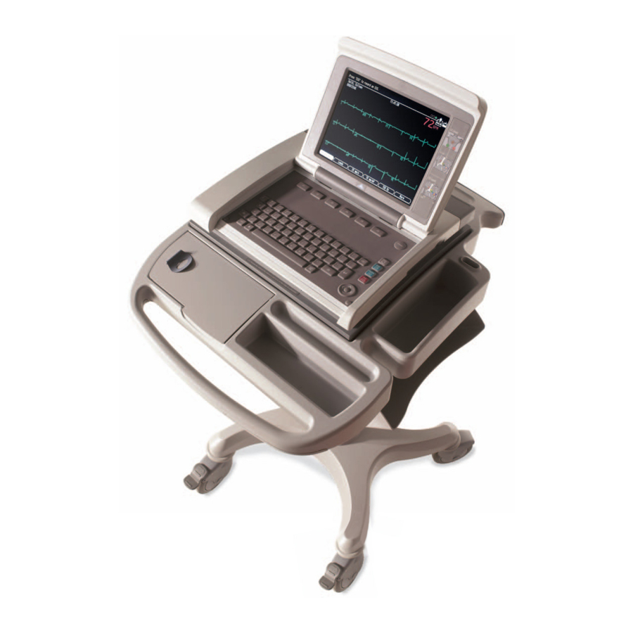
Installation: Preparation for Use Preparation for Use General Shown below is a completely assembled optional MAC 5500 Trolley. Use this picture for reference when installing trolley options. Acquisition Module Arm and Holder MAC 5500 Front Cover Trolley Serial Locking Swivel... -
Page 58: Trolley Height Adjustment
Installation: Preparation for Use Trolley Height Adjustment The optional MAC 5500 Trolley can be assembled for one of two heights, 92.07 cm (36.25 inches) or 84.45 cm (33.25 inches). The trolley is normally shipped at the 92.07 cm (36.25 inches) height but can be changed to fit your needs. To change to... - Page 59 Installation: Preparation for Use CAUTION Do not over tighten. Over tightening the bolts may cause them to strip. Revision E MAC 5500 resting ECG analysis system 3-5 2020299-020...
-
Page 60: Installing The Mac 5500 Resting Ecg Analysis System
Installation: Preparation for Use Installing the MAC 5500 resting ECG analysis system To secure the MAC 5500 to the trolley assembly, follow these steps: Lock the wheels to prevent the trolley from rolling. Remove the end panel by pulling out and up. - Page 61 Installation: Preparation for Use Secure the MAC 5500 to the trolley by tightening the three captive screws located under the trolley tray. Replace the end panel by pushing up and in until you hear a snap. Unlock the wheels to allow free movement of the trolley.
-
Page 62: Installing The Optional External Modem Kit
Installing the Optional External Modem Kit NOTE The internal modem is standard for the MAC 5500. The modem and its mounting bracket comes assembled and ready to install on the trolley. To install a modem kit on the trolley, complete the following steps: Find the modem mounting site located under the Acquisition Module support arm at the rear of the trolley where the kit is to be installed. - Page 63 Installation: Preparation for Use Plug the modem cable into connector port 2 on the MAC 5500. Refer to the operator’s manual for information on using the modem. Revision E MAC 5500 resting ECG analysis system 3-9 2020299-020...
-
Page 64: Magnetic Card Reader Installation
Installation: Preparation for Use Magnetic Card Reader Installation The Magnetic Card Reader and its mounting bracket are assembled and ready to install on the trolley. Parts are included for two different trolley styles. Disregard and do not use the parts indicated in the following illustration. Do Not Use These Parts Card Reader... - Page 65 At the front, hold the cable to the side so it clears the front panel as you replace the panel. Plug the cable connector into port A then replace the back panel. Refer to the MAC 5500 Operator’s Manual for information on using the Magnetic Card Reader. Revision E MAC...
-
Page 66: Bar Code Reader Installation
Installation: Preparation for Use Bar Code Reader Installation The Bar Code Reader and its mounting bracket are ready to install on the trolley. To install the Bar Code Reader and its cable mounting bracket on the trolley, complete the following steps: Barcode Reader Cable... - Page 67 Internal Access Port A Button Next fasten the cable and clamp to the clamp bracket, then close the MAC 5500. Observe that there is enough slack to allow free movement of the cable when re- opening the MAC 5500. Not enough cable slack.
-
Page 68: Type-S Trolley Assembly
Installation: Preparation for Use Type-S Trolley Assembly To mount the MAC 5500 to the Type-S trolley, follow the steps in the illustration below. Route patient cable through trolley and fasten with cable clamp as shown below. 3-14 MAC 5500 resting ECG analysis system Revision E... -
Page 69: Mac 5500 St Requirements And Configuration
Connection Requirements - Use cable PN 2008112-001 to connect from the MAC5500 port 1 to the Colin serial port. Use cable PN 2008111-001 to connect from the MAC 5500 ANA/TTL port to the Colin QRS trigger input. Device Configuration Requirements - None MAC 5500 Configuration Requirements –... -
Page 70: Compatible Ge Medical Systems Information Technologies Treadmills
MAC 5500 port 1 to the treadmill serial port. Device Configuration Requirements – None. MAC 5500 Configuration Requirements – Use the Edit Protocol application to set the protocol Test Type to Treadmill in MPH or Treadmill in Km/H for protocols that will be used with this treadmill. -
Page 71: Bicycle Ergometers
Connection Requirements – Use cable PN 2008109-001 (Ergoline 800), PN 2008114-001 (Ergoline 900), or PN 2007981-001 (Lode Ergometer), to connect from the MAC 5500 ANA/TTL port to the ergometer analog control port. NOTE For any other ergometer, the customer is responsible for making the appropriate cable. - Page 72 Installation: MAC 5500 ST Requirements and Configuration For your notes 3-18 MAC 5500 resting ECG analysis system Revision E 2020299-020...
- Page 73 Troubleshooting: Troubleshooting Revision E MAC 5500 resting ECG analysis system 4-1 2020299-020...
- Page 74 Troubleshooting: For your notes MAC 5500 resting ECG analysis system Revision E 2020299-020...
-
Page 75: Assembly Descriptions
Troubleshooting: Assembly Descriptions Assembly Descriptions Introduction The troubleshooting information in this chapter helps you narrow service problems to one of the replaceable assemblies. These assemblies, illustrated in the block diagram, are discussed in more detail in the individual assembly chapters along with replacement procedures. -
Page 76: General Fault Isolation
Troubleshooting: General Fault Isolation General Fault Isolation Power-up Self-test See the MAC 5500 Operator’s Manual, Chapter 2, “Equipment Overview: Getting Started” to verify operation. On power-up, the system automatically runs an internal self-test. If all circuits test good, the start up screen displays. If the equipment is not working properly, ask yourself the following questions. -
Page 77: Power-Up Flow Chart
Troubleshooting: General Fault Isolation Power-up Flow Chart Revision E MAC 5500 resting ECG analysis system 4-5 2020299-020... -
Page 78: Poor Quality Ecgs
Troubleshooting: General Fault Isolation Poor Quality ECGs Poor quality ECGs can be caused by factors in the environment, inadequate patient preparation, hardware failures related to the acquisition module, leadwires, cables, or problems in the unit. Use a simulator to obtain an ECG report. If the report is good, the problem is external to the unit. -
Page 79: Visual Inspection
Troubleshooting: General Fault Isolation Visual Inspection A thorough visual inspection of the equipment can save time. Small things— disconnected cables, foreign debris on circuit boards, missing hardware, loose components—can frequently cause symptoms and equipment failures that may appear to be unrelated and difficult to track. NOTE Take the time to make all the recommended visual checks before starting any detailed troubleshooting procedures. -
Page 80: Diagnostic Tests
Troubleshooting: Diagnostic Tests Diagnostic Tests Introduction Verify that the MAC 5500 resting ECG analysis system operates properly by running the diagnostic tests. These tests check the operation of the display screen, speaker, keyboard, thermal writer, battery, and communication. Detailed information displays on screen. -
Page 81: System Diagnostics Main Menu
Troubleshooting: Diagnostic Tests Select Miscellaneous Setup. Select the System password line and type the new password in the space. Press the Enter key. Select Save Setup from the System Setup menu. Select To system. System Diagnostics Main Menu Use the arrow pad control to highlight a menu item, then press the Enter key to select it. -
Page 82: Speaker Test
NOTE The display shows keys in the upper part of the screen that are only available with the MAC 5500 ST keyboard. Check both of the Shift keys by pressing each in combination with a letter to display a capital letter. -
Page 83: Writer Tests
Troubleshooting: Diagnostic Tests Writer Tests Run the writer tests to check the motor speed control, paper speed, paper tracking, paper cueing, and print head quality. During the tests, make the following general checks. The first character printed should not be distorted. This checks start-up speed. ... - Page 84 Troubleshooting: Diagnostic Tests Roller Test (Uneven darkness can appear if AC power is on during this test.) After cueing, printing should start at approximately 13–14 mm on the page. The pattern appears as diagonal light and dark wavy bands. ...
-
Page 85: Battery Tests
Troubleshooting: Diagnostic Tests Battery Tests NOTE The minimum discharge capacity is 2000 mAH. Consider replacing the battery if this number is less than 2000 mAH. Battery Status Displays, and constantly updates, the following information: Percent of charge remaining Battery voltage (With a reading of 80% or more for percent of charge remaining, the battery voltage should be between 15 and 24 volts. -
Page 86: Battery Charge Test
Troubleshooting: Diagnostic Tests Battery temperature Battery charge status Percent of charge remaining Battery Charge Test This test completely discharges the battery, if necessary, then monitors a charge cycle. NOTE This test can take up to 6 hours to run. The “Battery Discharge Test” is a better indicator of the condition of the battery. -
Page 87: External Modem Test
Troubleshooting: Diagnostic Tests External Modem Test Connect a modem to COM 2 and select External Modem Test. The test returns the modem ID number, firmware rev, and current parameter settings. If communication with the modem is unsuccessful, the ID and firmware rev display N/A. Internal Modem Test Select Internal Modem Test. -
Page 88: Analog Input Test
Pin numbers refer to the ANA/TTL port. Floppy Drive Tests This test does not apply to the MAC 5500 system. Follow the instructions on screen. A read/write test is performed on a formatted floppy disk and a pass/fail test result is displayed. Try another disk if this test fails. If this test continues to fail, contact GE Medical Systems-Information Technologies for service. -
Page 89: Sd Card Tests
Troubleshooting: Diagnostic Tests Press F to format and any other key to escape. NOTE Do not format the internal storage memory if it contains data which has not yet been transferred. SD Card Tests Insert SD card which is not write-protected. Select SD Card Tests. -
Page 90: Equipment Problems
Troubleshooting: Equipment Problems Equipment Problems ECG Data Noise If the acquired ECG data displays unacceptable noise levels: Verify proper electrode placement. Verify proper electrode application. (Perspiration and dead skin must be removed from the electrode site.) Check for defective or out of date electrodes. ... -
Page 91: System Errors
The following errors may occur while you are operating this system. You may be required to perform some action. If you perform the recommended actions and the condition still remains, contact authorized service personnel. See “How to Reach Us” to find out how to contact GE Medical Systems Information Technologies. Problem... -
Page 92: Frequently Asked Questions
Store. Format an SD Card Q: How do I format an SD card in the MAC 5500? A: Most secure digital cards do not require formatting. In the event an unformatted SD card is used with the system, the following message will display: This SD Card cannot be read and requires formatting. -
Page 93: Battery Capacity
Battery Capacity Q: What is the capacity of the battery? A: We recommend that the MAC 5500 be plugged into a wall outlet whenever it is not in use. However, the life of the battery is approximately 100 ECGs and one- page reports or six hours of continuous operation (without printing). -
Page 94: Passwords
If you want the MAC 5500 or 12SL interpretation included on the ECG, put the number of copies you want in the “with” column. If you do not want the MAC 5500 interpretation to print on the ECG, put the number of copies you want in the “without” column. ... -
Page 95: Entering Patient Data
Q: Why do I lose the Referring MD and Technician names off of my reports when I transmit records to the MUSE system? A: Your MAC 5500 may be transmitting to the SDLC modem on the MUSE system instead of the CSI modem. Check in System Setup to make sure you are transmitting to the MUSE system CSI phone number. -
Page 96: Input And Output Connectors
Troubleshooting: Input and Output Connectors Input and Output Connectors The following pages detail the input/output signals for those connectors. The pin-by- pin descriptions identify the signal names and pin outs for each connector on the unit. A Pins (J1) Table 2. A Pins (J1) Name Data Ground... -
Page 97: Com2 Pins (J5)
Troubleshooting: Input and Output Connectors COM2 Pins (J5) Table 4. COM2 Pins (J5) Name Ground +12V Analog Pins (J6) Table 5. Acquisition Module Connector (J6) Name +12V DC Output 1 TTL Trigger Output Ground Ground DC Output 2 DC Input 1 ECG Output DC Input 2 Revision E... -
Page 98: Ext. Vid. Pins (J7)
Troubleshooting: Input and Output Connectors EXT. VID. Pins (J7) Table 6. External VGA Video (J7) Name Red Video Green Video Blue Video Ground Ground Ground Ground Ground Ground Ground Horizontal Sync Vertical Sync 4-26 MAC 5500 resting ECG analysis system Revision E... -
Page 99: Cpu Pcb Input/Output Signals
Troubleshooting: CPU PCB Input/Output Signals CPU PCB Input/Output Signals Battery Pack/Monitor, J2 Pin No. Signal 18V Battery Power 18V Battery Power Battery Temperature Sense 3V Temperature Sense Power Battery Ground Battery Ground LCD Backlight, J4 Pin No. Signal 12V Power 12V Power 12V Power Ground... -
Page 100: Lcd, J10
Troubleshooting: CPU PCB Input/Output Signals Keyboard, J8 (Continued) Sense3 Sense5 Sense6 Sense7 Drive0 Drive1 Drive2 Drive3 Drive4 Ground Power Key Drive5 Drive6 Drive7 Drive8 Drive9 Drive10 LCD, J10 Pin No. Signal Ground Pixel Clock Hsync Vsync Ground R0 (LSB) R5 (MSB) Ground G0 (LSB) 4-28... -
Page 101: Power Supply/Motor, J11
Troubleshooting: CPU PCB Input/Output Signals LCD, J10 (Continued) G5 (MSB) Ground B0 (LSB) B5 (MSB) Ground Data Enable 3V Power 3V Power Power Supply/Motor, J11 Pin No. Signal Motor Encoder B 5V Power Motor A Motor Encoder A Ground Motor B 28V Power Ground Battery Charge LED... -
Page 102: Thermal Printer, J12
Troubleshooting: CPU PCB Input/Output Signals Thermal Printer, J12 Pin No. Signal Thermal Printer Power Thermal Printer Power Thermal Printer Power Thermal Printer Power Thermal Printer Power Thermal Printer Power Thermal Printer Power Ground Ground Ground Ground Ground Ground Ground Cue Sense 5V Main Power Ground Data Strobe... -
Page 103: Floppy Disk Drive, J13
Troubleshooting: CPU PCB Input/Output Signals Floppy Disk Drive, J13 (for floppy drive — not installed Pin No. Signal 5V Power Index 5V Power Drive Select 0 5V Power Disk Change Media Sense 0 Media Sense 1 Motor Select 0 Direction Step Ground Write Data... -
Page 104: Acquisition Module, J14
Troubleshooting: CPU PCB Input/Output Signals Acquisition Module, J14 Pin No. Signal Power Ground TX+ (RS485) TX- (RS485) RX+ (RS485) RX- (RS485) 4-32 MAC 5500 resting ECG analysis system Revision E 2020299-020... - Page 105 Maintenance: Maintenance Revision E MAC 5500 resting ECG analysis system 5-1 2020299-020...
- Page 106 Maintenance: For your notes MAC 5500 resting ECG analysis system Revision E 2020299-020...
-
Page 107: Introduction
Maintenance: Introduction Introduction Recommended Maintenance Regular maintenance, irrespective of usage, is essential to ensure that the equipment will always be functional when required. WARNING Failure on the part of all responsible individuals, hospitals or institutions, employing the use of this device, to implement the recommended maintenance schedule may cause equipment failure and possible health hazards. -
Page 108: Inspection And Cleaning
Maintenance: Inspection and Cleaning Inspection and Cleaning Visual Inspection Perform a visual inspection of all equipment and peripheral devices daily. Turn off the unit and remove power before making an inspection or cleaning the unit. Check the case and display screen for cracks or other damage. ... - Page 109 Maintenance: Inspection and Cleaning Thermal Printhead Revision E MAC 5500 resting ECG analysis system 5-5 2020299-020...
-
Page 110: Battery And Patient Cable Replacement
Maintenance: Battery and Patient Cable Replacement Battery and Patient Cable Replacement Battery Replacement Press the internal access button to open the unit. Slide the battery release button in the direction of the arrow and lift the battery out. Install a new battery and close the unit. Patient Cable Replacement Press the internal access button to open the unit. -
Page 111: Disassembly Guidelines
Trolley Disassembly Lock the wheels, remove the rear trolley panel then loosen the three captive screws located under the trolley. Pull the MAC 5500 up and up toward you. Lift the unit from the trolley. Revision E MAC 5500 resting ECG analysis system 5-7... -
Page 112: Type-S Trolley Disassembly
Maintenance: Disassembly Guidelines Type-S Trolley Disassembly To dismount the MAC 5500 from the Type-S trolley, follow the steps shown in the following illustration. Power Supply NOTE A #10 TORX driver is required for disassembly and assembly of the power supply. -
Page 113: Reassembly
Maintenance: Disassembly Guidelines Screws (3) Ground Wire Wiring Harness Reassembly Reassemble the power supply reversing the steps for removal. Before replacing the screws, ensure that the ground wire is routed through the notch in the plastic and not pinched. Top Cover Removal NOTE It is not necessary to remove the Power Supply prior to removing the top cover. -
Page 114: Reassembly
Maintenance: Disassembly Guidelines Turn the unit right side up and press the internal access button and raise the top of the unit. Remove four (4) TORX screws. Four (4) TORX screws Lower the top of the unit and lock in place. Raise the display to the vertical position. -
Page 115: Display/Keyboard Assembly
Maintenance: Disassembly Guidelines Display/Keyboard Assembly Removal Remove the top cover following the procedures above. Disconnect the three cables connecting the display/keyboard assembly to the main PCB. NOTE Two of these cables have locked connectors that must be lifted up to release the cables. -
Page 116: Display/Keyboard Reassembly
Maintenance: Disassembly Guidelines Display/Keyboard Reassembly Display Ground Display Ground Roll Pin LCD Flex Cable Fasten to writer as shown Backlight LCD Flex Cable Flex Cable Backlight Flex Cable Flex Cable Align Flex to Pin Slots Insert both flex cables through flex cable slots and position them as shown. Tilt the display/keyboard assembly to the left and with the roll pin of the hinge (metal rod) parallel to the left hinge base, insert the rod into the left hinge base and lower the display/keyboard assembly in place. -
Page 117: Main Cpu Board
Insert the new CPU board in place and mount using the screws set aside during disassembly. Reassemble the top cover and display/keyboard assemblies by reversing the steps for removal. Insert rear bezel into slot on back of MAC 5500 assembly as shown below. Revision E MAC 5500 resting ECG analysis system 5-13... - Page 118 Maintenance: Disassembly Guidelines Rotate bezel to the upright position as shown below. With the new bezel in place, replace the top cover by reversing the steps described previously. Replace the battery and proceed with software, serial number, and system setups as described in the following sections. 5-14 MAC...
-
Page 119: Software
Maintenance: Disassembly Guidelines Software After replacing the CPU board, you need to install or update the software on the board as follows: Connect the system to AC power. Keep the system connected to AC power during the software update and do not power off the system during the software update. -
Page 120: Service Only Setups
Maintenance: Disassembly Guidelines Programming Primary Boot... Programming Over System is Shutting Down If the boot code is being downgraded to an earlier version, a message similar to the following message displays. Current Boot Version: New Boot Version: Press ‘Enter’ to start Installation Press Enter. -
Page 121: Restore System Setups
Maintenance: Disassembly Guidelines the label of the system. Select/verify that No is selected for Update Primary Boot. Enter the Print head resistance. This number can be found on the print head label. Select the appropriate language in the Keyboard menu. Select Return. -
Page 122: Disable Options
Maintenance: Disassembly Guidelines Highlight Return and press Enter to return to the Basic System menu. Disable Options It is possible to disable an option. In the rare instance you may need this functionality, follow these steps: Within the system setup function, select Basic System. Select Option Activation. -
Page 123: Printhead Replacement
Maintenance: Disassembly Guidelines Printhead Replacement Removal Remove the top cover following the procedure above. Using a Phillips head screw driver, remove the two screws that hold the printhead to the printhead mounting plate. Open the writer assembly, disconnect and remove the printhead. Reassembly Record the resistance value of the new printhead. -
Page 124: Setting Up Lan Communications
Maintenance: Disassembly Guidelines Insert the new communications board, sliding it onto the rails until it is seated in place. Replace the panel surrounding the LAN and modem ports. Replace the battery and AC power cable. Setting up LAN Communications After replacing the communications board, use the following procedure to set up the system's LAN communications. - Page 125 13. Cycle power on the MAC 3500/MAC 5500 system. This ensures the network settings are reread from the communications board. 14. Wait at least 10 minutes and verify the MAC 3500/MAC 5500 can communicate with the MUSE system. Windows File Server 2000/2003 has an ARP cache that regenerates the MAC Address/Physical Address table every 10 minutes.
-
Page 126: Writer Roller/Carriage Assembly
Reassemble the writer roller/carriage assembly by reversing the above procedures. Trolley Casters Removal Remove the MAC 5500 and all loose items from the trolley and then place the trolley on its side. Locate the slot under the arrow on the bearing dust cap and using a small blade screwdriver, pry the cap from the caster to be removed. - Page 127 Maintenance: Disassembly Guidelines Using an Allen wrench, remove the bolt holding the caster to the trolley. Reassembly Install the replacement caster on the trolley. NOTE Ensure that the pins align with the holes on the fixed caster before fastening to the trolley. 57A, 58A Install the wheel and attach with the wheel bearing shaft and nut.
- Page 128 Maintenance: Disassembly Guidelines Using a small mallet, tap the bearing dust covers back in place. Set trolley upright and push to check alignment and free movement of casters. Replace the MAC 5500 unit. 5-24 MAC 5500 resting ECG analysis system Revision E...
-
Page 129: Functional Checkout Procedures
Maintenance: Functional Checkout Procedures Functional Checkout Procedures This checkout procedure applies to all MAC 5500 systems. NOTE The FRU checkout procedure for any listed FRU also applies to its internal PCBs and components. Perform the applicable product or product configuration dependant procedures when an asterisk * is listed. -
Page 130: Tools
Maintenance: Functional Checkout Procedures Table 4. Option Repairs (Continued) FRU / Option Tools Visual Inspection Checkout Procedure(s) Wireless Serial Server 1,2,5 1,3,5 LAN (Comm PCB) 1,2,5 1,3,5,19 Barcode Reader 1,2,5 1,3,8 Mag Card Reader 1,2,5 1,3,9 Treadmill or Ergometer I/F Cable 1,2,5 1,3,6 Blood Pressure Monitor... -
Page 131: Visual Inspection
Maintenance: Functional Checkout Procedures Visual Inspection Inspect the following for excess wear and or any visual signs of damage. Passed check for defective or broken patient cable/leadwires and out of date electrodes? Discussed electrode placement, skin prep, and patient related requirements with ECG Tech? Keyboard/LCD passed inspection? AC Power cord passed inspection? -
Page 132: Diagnostic Tests
Maintenance: Functional Checkout Procedures Diagnostic Tests 11. Battery Status Test meets Battery Current expectation? 12. Display diagnostic test successful? 13. Speaker test successful? 14. Keyboard test successful? 15. Writer diagnostic tests successful? 16. Read/Write Floppy Diagnostic Test successful? (Accurate test does not have to be performed)? 17. -
Page 133: Electrical Safety Checks
Maintenance: Functional Checkout Procedures Electrical Safety Checks 20. Current leakage and ground continuity test results meet requirements? Perform electrical safety checks when indicated. All indicated electrical safety checks require a pass/fail indication for steps performed. Record the measurement values in your debrief. Table 6. - Page 134 Maintenance: Functional Checkout Procedures Table 6. Electrical Safety Checks Leakage Step Result Condition UUT - ON Current Limits Ground Continuity Resistance Less than AC mains power cord ground prong to exposed metal ______ Pass/Fail surface (ground lug) 200m 1.
- Page 135 Maintenance: Functional Checkout Procedures For your notes Revision E MAC 5500 resting ECG analysis system 5-31 2020299-020...
- Page 136 Maintenance: Functional Checkout Procedures 5-32 MAC 5500 resting ECG analysis system Revision E 2020299-020...
- Page 137 Parts List: Parts List Revision E MAC 5500 resting ECG analysis system 6-1 2020299-020...
- Page 138 Parts List: For your notes MAC 5500 resting ECG analysis system Revision E 2020299-020...
-
Page 139: Ordering Parts
Parts List: Ordering Parts Ordering Parts General Information The FRU parts lists in this chapter supply enough detail for you to order parts for the assemblies considered field serviceable. To order parts, contact Service Parts at the address or telephone number on the, “How to Reach Us...,” page provided at the beginning of this manual. -
Page 140: Field Replaceable Units
Verify part numbers before ordering service parts (field replaceable units). See the tech memo series for this product for changes or additions to this list. For Technical Support parts reference, see pn 2026609-001, MAC 5500 Assembly. Field Replaceable Units Item... - Page 141 Parts List: Field Replaceable Units Field Replaceable Units (Continued) Item Part Number Keyboard Assembly (Resting), German 421115-102 Keyboard Assembly (Stress), German 421115-202 Keyboard Assembly (Resting), French 421115-103 Keyboard Assembly (Stress), French 421115-203 Keyboard Assembly (Resting), Spanish 421115-104 Keyboard Assembly (Stress), Spanish 421115-204 Keyboard Assembly (Resting), Swedish 421115-105...
- Page 142 Parts List: Field Replaceable Units Field Replaceable Units (Continued) Item Part Number Power Cord Italian 10A 250V 8FT 401855-003 Power Cord Israeli 10A 250V 8FT 401855-004 Wire Harness 10A 125V 6.5FT 401855-005 Wire Harness 10A 250V 6.5FT 401855-006 Power Cord Swiss 10A 250V 8FT 401855-007 Power Supply Cord, Indian 10A 250V 2.5M 401855-108...
- Page 143 Parts List: Field Replaceable Units Field Replaceable Units (Continued) Item Part Number Barcode Scanner Kit, German 2018626-002 Barcode Scanner Kit, French 2018626-003 Barcode Scanner Kit, Spanish 2018626-004 Barcode Scanner Kit, Swedish 2018626-005 Barcode Scanner Kit, Italian 2018626-006 Barcode Scanner Kit, Norwegian 2018626-009 Barcode Scanner Kit, Danish 2018626-010...
- Page 144 Parts List: Field Replaceable Units Field Replaceable Units (Continued) Item Part Number Trolley Caster Swivel (Anti-Static) 2017785-002 Trolley Caster Kit (Anti-Static) 2024418-001 North American MobileLink Assembly (Ultra High Security) 2023922-001 North American MobileLink Assembly (Symbol) 2014403-002 European MobileLink Assembly (Symbol) 2014403-003 CPU Board 801212-007...
- Page 145 Parts List: Field Replaceable Units Field Replaceable Units (Continued) Item Part Number FIPS Wireless Silex Serial Server (US government use only) 2047733-001 Assembly — Wireless Silex Serial Server (USA) 2034530-001 Assembly — Wireless Silex Serial Server (Europe) 2034530-002 Assembly — FIPS Wireless Silex Serial Server (US 2034530-003 government use only) Assembly —...
- Page 146 Parts List: Field Replaceable Units 6-10 MAC 5500 resting ECG analysis system Revision E 2020299-020...
-
Page 147: Appendix A -Abbreviations
Appendix A –Abbreviations: Appendix A – Abbreviations Revision E MAC 5500 resting ECG analysis system A-1 2020299-020... - Page 148 Appendix A –Abbreviations: For your notes MAC 5500 resting ECG analysis system Revision E 2020299-020...
-
Page 149: Standard Abbreviations
Appendix A –Abbreviations: Standard Abbreviations Standard Abbreviations ampere A-ang antianginal A-arh antiarrhythmic A-coa anticoagulants A-hyp antihypertensive A1 - A4 auxiliary leadwires AAMI American Association of Medical Instrumentation ambulatory blood pressure ac, AC alternating current ACLS Advanced Cardiac Life Support analog-to-digital adjustable automotive glass ampere hours... - Page 150 Appendix A –Abbreviations: Standard Abbreviations board, baud BDGH binding head BetaB beta blockers BKSP backspace black blue Blvd boulevard blood pressure beats per minute BRIT Britain brown British Standards Institute British thermal unit CalcBlk calcium blockers CAPOC Computer Assisted Practice of Cardiology CASE Computer Aided System for Exercise Catoprl...
- Page 151 Appendix A –Abbreviations: Standard Abbreviations Danish Dat/Tim date/time decibel (referenced to 1 milliwatt into 600 ohms) dc, DC direct current double density, day Digital Diagnostic Diskette Digital Equipment Corporation, December delete DEMO demonstration designation DevId device identification Diag diagnostic Digital Digitalis Digitox Digitoxin...
- Page 152 Appendix A –Abbreviations: Standard Abbreviations flat head FLRAM flash RAM French FrntEnd front end frequency shift keying foot, feet Furosem Furosemide gram, acceleration due to gravity Great Britain GERM German, Germany ground, digital ground (dc common) green gray high, vector electrode site, vector lead HDLC high-level data link control Hex, HEX...
- Page 153 Appendix A –Abbreviations: Standard Abbreviations keyboard line level one level two left arm pound liquid crystal display Lcl Line local line Ld Grps lead groups light-emitting diode left hand Lidoca Lidocaine left leg location LocPc Local MAC PC LogRetry log retry limited meter megabyte, metric, vector electrode site, vector lead, male...
- Page 154 Appendix A –Abbreviations: Standard Abbreviations neutral not available not applicable no connection Nitrate nitrates near letter quality non-maskable interrupt NMOS N-channel metal-oxide semiconductor number normally open norm normal nanoseconds Normal Sinus Rhythm off, original other errors original equipment manufacturer off-hook relay OneSec one sector orange...
- Page 155 Appendix A –Abbreviations: Standard Abbreviations phase shift keying power supply unit Psych psychotropic pull-up signal polyvinyl chloride pulse-width modulation power PWR CRD power cord transistor quality assurance, Q wave amplitude Quality Assurance Deviation quadrature amplitude modulation (phase and amplitude modulation) quality control Q wave duration QRS complex (portion of ECG waveform), interval of ventricular...
- Page 156 Appendix A –Abbreviations: Standard Abbreviations s, S second, select, switch s wave amplitude slow-blow safe current limits schematic diagram, S wave duration serial input/output errors second sec.s seconds SEER Solid-state Electronic ECG Recorder SING Singapore Spanish S wave amplitude SPDT single-pole, double-throw SRAM static RAM...
- Page 157 Appendix A –Abbreviations: Standard Abbreviations precordial lead V456 V4, V5, V6 precordial lead V ac volts, alternating current V dc voltage, direct current volt-amperes variable Verband Deutscher Elektrotechniker (German regulatory agency) Vent. ventricular ventricular fibrillation video graphics array versatile interface adapter violet Volt voltage...
- Page 158 Appendix A –Abbreviations: Standard Abbreviations asterisk suffix are active at their relatively higher potential, or “active-high.” 12SL 12 simultaneous leads A-12 MAC 5500 resting ECG analysis system Revision E 2020299-020...
-
Page 159: Appendix B - Technical Specifications
Appendix B – Technical Specifications: Appendix B – Technical Specifications Revision E MAC 5500 resting ECG analysis system B-1 2020299-020... - Page 160 Appendix B – Technical Specifications: For your notes MAC 5500 resting ECG analysis system Revision E 2020299-020...
-
Page 161: Technical Specifications
Appendix B – Technical Specifications: Technical Specifications Technical Specifications Display Item Description Type 264mm (10.4 in.) diagonal graphics backlit AM LCD Resolution 640 x 480 pixels, with waveform enhancement Displayed Data Heart rate, patient name, ID, clock, waveforms, lead labels, speed, gain and filter settings, warning messages, prompts and help messages Computerized Electrocardiograph Item... -
Page 162: Writer
Appendix B – Technical Specifications: Technical Specifications Writer Item Description Type Thermal dot array Speeds 5, 12.5, 25, 50 mm/s (same as display) Number of Traces 3, 6, 12, or 15 user-selectable (same as display) Sensitivity/Gain 2.5, 5, 10, 20, 10/5 (split calibration) mm/mV (same as display) Speed Accuracy ±... -
Page 163: Hi-Res And Phi-Res Signal-Averaged Electrocardiography
Appendix B – Technical Specifications: Technical Specifications Hi-Res and PHi-Res Signal-Averaged Electrocardiography Item Description Frequency Response/Input -3 dB @ 0.01 and 250 Hz Frequency Response/Output Upper Limit 250 Hz Lower Limit 0.01, 25, 40 or 80 Hz Sensitivities Raw Data and Template 20 mm/mV Average Beat 20 mm/mV and 50 mm/mV... - Page 164 Batteries Disposing of battery by fire or burning will cause the battery to explode. The battery is recyclable. Follow local environmental guidelines concerning disposal and recycling. Batteries may be returned to GE Medical Systems Information Technologies service for recycling. Device Recyclable.
-
Page 165: Safety
Ordinary Liquids Handling of Disposable Supplies and Use only parts and accessories manufactured or recommended by GE Medical Systems Other Consumables Information Technologies. Follow manufacturer’s instructions for use for disposable/ consumable products. Follow local environmental guidelines concerning the disposal of hazardous materials. - Page 166 Appendix B – Technical Specifications: Technical Specifications For your notes MAC 5500 resting ECG analysis system Revision E 2020299-020...
-
Page 167: Appendix C - Electromagnetic Compatibility
Appendix C – Electromagnetic Compatibility: Appendix C – Electromagnetic Compatibility Revision E MAC 5500 resting ECG analysis system C-1 2020299-020... - Page 168 Appendix C – Electromagnetic Compatibility: For your notes MAC 5500 resting ECG analysis system Revision E 2020299-020...
-
Page 169: Electromagnetic Compatibility (Emc
Guidance and Manufacturer's Declaration - Electromagnetic Emissions The MAC 5500 is intended for use in the electromagnetic environment specified below. It is the responsibility of the customer or user to ensure that the MAC 5500 is used in such an environment. Emissions Test... -
Page 170: Guidance And Manufacturer's Declaration - Electromagnetic Immunity
Guidance and Manufacturer's Declaration - Electromagnetic Immunity The MAC 5500 is intended for use in the electromagnetic environment specified below. It is the responsibility of the customer or user to ensure that the MAC 5500 is used in such an environment. Immunity Test... - Page 171 Guidance and Manufacturer's Declaration - Electromagnetic Immunity The MAC 5500 is intended for use in the electromagnetic environment specified below. It is the responsibility of the customer or user to assure that the MAC 5500 is used in such an environment. Immunity Test...
-
Page 172: Recommended Separation Distances
RF communication equipment and the MAC 5500. The MAC 5500 is intended for use in the electromagnetic environment on which radiated RF disturbances are controlled. The customer or the user of the MAC 5500 can help prevent electromagnetic interference by maintaining a minimum distance... -
Page 173: Compliant Cables And Accessories
The table below lists cables, transducers, and other applicable accessories with which GE Medical Systems claims EMC compliance. NOTE Any supplied accessories that do not affect EMC compliance are not included. - Page 174 Appendix C – Electromagnetic Compatibility: Electromagnetic Compatibility (EMC) For your notes MAC 5500 resting ECG analysis system Revision E 2020299-020...
- Page 175 Index Revision E MAC 5500 resting ECG analysis system Index-1 2020299-020...
- Page 176 Index-2 MAC 5500 resting ECG analysis system Revision E 2020299-020...
- Page 177 Index modem test 4-15 abbreviations A-3 ACI-TIPI report missing 4-18 operating conditions B-5 acquisition module test 4-15 amber battery light 2-4 analog input test 4-16 pace detection B-3 analog output test 4-15 paper B-4 passwords 4-22 patient data 4-23 back panel connectors 2-5 patient questions 4-21 battery capacity 4-21 product code 1-9...
- Page 178 Index Index-4 MAC 5500 resting ECG analysis system Revision E 2020299-020...
- Page 180 Asia Headquarters GE Medical Systems GE Medical Systems GE Medical Systems Information Technologies GmbH Information Technologies, Inc. Information Technologies Asia; GE (China) Co., Ltd. 8200 West Tower Avenue Munzinger Straße 3-5 No. 1 Huatuo Road Milwaukee, WI 53223 USA D-79111 Freiburg...
Need help?
Do you have a question about the MAC 5500 and is the answer not in the manual?
Questions and answers