GE Marquette MAC 1200 Operator's Manual
Hide thumbs
Also See for Marquette MAC 1200:
- Operator's manual (200 pages) ,
- Service manual (151 pages) ,
- Servicing instructions (96 pages)
Table of Contents
Advertisement
Quick Links
Advertisement
Table of Contents

Related Manuals for GE Marquette MAC 1200


Summary of Contents for GE Marquette MAC 1200
- Page 1 ® 1200 Operator's Manual Version 1 227 492 04 GA (USA) Revision C...
- Page 2 Walkmom are trademarks of GE Marquette Medical Systems, Inc. Revision History This manual is subject to the GE Marquette change order service. The revision letter which follows the document part number, changes with every update of the manual. Part No./ Revision...
- Page 3 MAC 1200 Option Codes MAC 1200 Option Codes In addition to the software supplied with the unit, optional programs may be purchased to upgraded the MAC 1200 performance features. In order to use a new option, you need to activate it by entering the option code number (refer to section 9.8 for details).
- Page 4 How To Reach Us How To Reach Us Service calls Tech support Contact various service, supplies, and repair Tech Support has the most current information about personnel using the following telephone numbers and your equipment, and can provide assistance with any addresses.
- Page 5 For additional information contact one of the offices #2 Leng Kee Road listed below. 04-04A Thye Hong Centre Singapore 0315 Headquarters Telephone: (65) 471-2133 GE Marquette Medical Systems, Inc. Fax: (65) 471-1540 8200 West Tower Avenue Milwaukee, Wisconsin 53223 Telephone: 414-355-5000 800-558-5120 (U.S. only)
- Page 6 General Information General Information • Standards compliance: European Council Directive 93/42/EEC IEC60601-1-2/EN 60601-1-2 "Electromagnetic Compatibility - Medical Electrical Equipment". CISPR11 / EN 55011 "Radio interference emission" IEC 60601, protection class I MDD class IIb UL 2601-1 • The symbol means: Consult accompanying documents.
- Page 7 Contents 1 INTENDED USE AND FUNCTIONAL DESCRIPTION 2 CONTROLS AND INDICATORS 3 PUTTING THE DEVICE INTO OPERATION AND PERFORMANCE TEST 3.1 S AFETY NFORMATION 3.2 P OWER UPPLY 3.3 I NSTALLATION AND AINS ONNECTION 3.4 P ERFORMANCE HECK 3.5 G ENERAL EVICE ETTINGS...
-
Page 8: Table Of Contents
Contents 8 ECGS OF PACEMAKER PATIENTS / ECG RECORDING DURING DEFIBRILLATION 9 SYSTEM SETUP 9.1 S ASIC ACTS 9.2 12 L 9.3 6 L 9.4 A RRHYTHMIA 9.5 G ENERAL EVICE ETTINGS 9.6 C OMMUNICATION 9.7 P ATIENT 9.8 O PTION 10 LOADING CHART PAPER 11 CLEANING, DISINFECTION AND MAINTENANCE... - Page 9 Intended Use and Functional Description 1 Intended Use and Functional Description The MAC 1200 is an ECG acquisition and recording The device operates from both AC and DC system designed and manufactured by Marquette (rechargeable batteries) power sources. Medical Systems. The unit's performance features can be upgraded −...
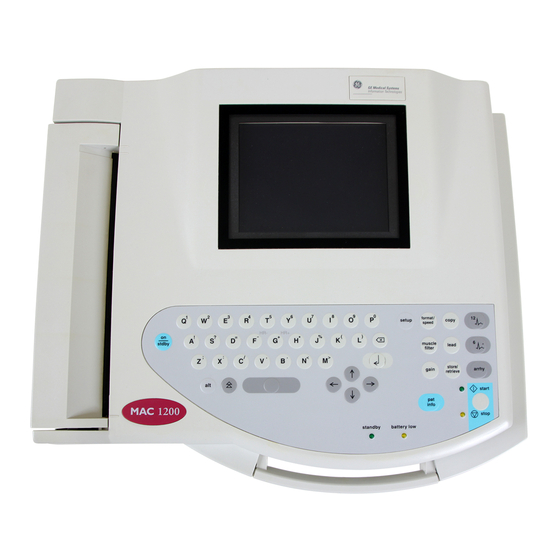
- Page 10 Controls and Indicators 2 Controls and Indicators 13 15 10 12 14 format/ setup copy speed muscle lead stdby filter store/ < > gain arrhy retrieve start info stop standby battery low Figure 2-1. Controls and indicators of the MAC 1200 electrocardiograph MAC®...
- Page 11 Controls and Indicators Power input 14 Selects the ECG lead in 6 Lead Mode (in 12 Lead Mode, on the display only) Paper door, windows allows you to check the paper supply 15 Sends ECG to memory/retrieves ECG from memory Patient cable connector 16 Selects the 12 Lead Mode Serial interface (see chapter 13 "Technical...
- Page 12 Putting the Device into Operation and Performance Test 3 Putting the Device into Operation and Performance Test 3.1 Safety Information Caution indicates a potentially hazardous situation which, if • This manual is an integral part of the device. It not avoided, may result in minor or moderate injury should always be kept near the device.
- Page 13 Putting the Device into Operation and Performance Test WARNINGS ACCESSORIES (SUPPLIES) — Use only the OPERATOR — The user must have received original Marquette cables. Do not connect other adequate training in the use of the MAC 1200 and signal sources to the cables. The responsibility for must be capable of applying it properly.
- Page 14 Putting the Device into Operation and Performance Test CAUTIONS MAINTENANCE — Regular preventive EMC — Magnetic and electrical fields are capable maintenance should be carried out annually, of interfering with the proper performance of the inspections of equipment with measuring functions device.
- Page 15 Putting the Device into Operation and Performance Test NOTES Literature - The MAC 1200 is designed to comply with IEC Medical Device Directive 93/42/EEC 60601/ EN 60601 requirements. It is Class I equipment and has a built-in rechargeable EN 60601-1/1990 + A1: 1993 + A2: 1995: Medical electrical power source.
- Page 16 Putting the Device into Operation and Performance Test 3.2 Power Supply The units are powered from the power line or from store/ format/ the rechargeable battery. retrieve speed The battery charges automatically when the unit is connected to the power line and the standby indicator 23 is illuminated (Figure 3-1).
- Page 17 Putting the Device into Operation and Performance Test 3.3 Installation and Mains Connection Figure 3-2 shows a practical arrangement of patient and recorder. For interference-free operation, it is important that the patient cable and the power cord do not run parallel. •...
- Page 18 Putting the Device into Operation and Performance Test 3.5 General Device Settings Parameter System Options The table at left shows the general device settings Defaults that can be modified and the system defaults. For instructions on changing the device setup, refer Ordering empty text box selection from a list Physician...
- Page 19 Putting the Device into Operation and Performance Test 3.6 Connecting External Devices Via the serial interface, the electrocardiograph can Warning be connected to a MUSE CV Information System. − Connecting external devices to the RS232 These external devices can be connected directly or interface of the electrocardiograph creates a via a modem.
- Page 20 Preparations for ECG Recording 4 Preparations for ECG Recording 4.1 Connecting the Patient Cable Use the 10-leadwire patient cable for acquisition of the 12 standard ECG leads. • Connect the patient cable to connector 3 (Figure 4-1). Figure 4-1. ECG signal input Warning For reasons of patient safety, use only the original Marquette patient cable.
- Page 21 Preparations for ECG Recording 4.2.2 Applying Electrodes (Thorax) • Shave application points, if necessary. 4.2.3 Electrode Placement for Standard Leads (l, II, III, aVR, aVL, aVF, VI...V6) For acquisition of the standard ECG leads four electrodes must be applied on the limbs and six on the chest.
- Page 22 Preparations for ECG Recording 4.3 Artifact Due to Poor Electrode Application The electrocardiograph is equipped with state-of- On the display this condition is indicated by **** the-art electronic utilities that ensure artifact-free instead of the electrode label (e.g. at i, Figure 5-1). recordings.
- Page 23 Preparations for ECG Recording 4.4 Entering Patient Data − For entry of numbers (e.g. date of birth), it is not It is possible to enter patient data and have them necessary to press the Shift key. annotated on the recording for easy archiving of patient records.
- Page 24 Preparations for ECG Recording New patient Ordering Physician / Referring Physician / yes: existing patient data are deleted Technician no: entered data can be edited When you choose "yes" for "New patient", the default names entered in the General Settings will appear here.
- Page 25 Recording in 12 Lead Mode 5 Recording in 12 Lead Mode Several system settings can be customized. In this manual they are labeled "configurable". Please bear in mind that no automated analysis of The following information refers to a unit with the ECG signals is completely reliable.
- Page 26 Recording in 12 Lead Mode 5.2 Recording On power up, the unit defaults to the 12 Lead Mode (system defaults) (configurable). − Before recording the ECG, patient data can be entered ( ). We recommend to enter the info patient's name to annotate it on every report. −...
- Page 27 Recording in 12 Lead Mode With the system defaults unchanged, the unit will activate the following functions and settings after power-up: Please note that filters may suppress diagnostically − the 12 Lead Mode (configurable) relevant portions of the signal. Filters should −...
- Page 28 Recording in 12 Lead Mode 5.3 The Memory Function Units equipped with the optional MEMO function permit storage of the ECG including patient, store/ measurement and interpretation data with . The retrieve When the unit runs out of paper while printing all display will indicate the number of stored ECGs (40 stored ECGs (menu item "Print all stored ECGs"), max.).
- Page 29 When selected, this page will be physician for confirmation. appended to the respective report formats. It contains patient data, measurement results (MEAS), GE marquette MAC 1200 John Doe University Hospital, Dr. Williams interpretative statements (DIAG), medians and the male, Caucasian, 32 years, 6.7 ft., 172 lb, 161/133 mmHg Pacemaker 414 355 378...
- Page 30 Recording in 12 Lead Mode 5.5 ECG Transmission via Modem Resting ECGs acquired in 12 Lead Mode can be transferred to host systems (MUSE CV Information Warning System (version 004A or higher)). The transfer can Observe the safety information given in section 3.6 take place either directly or via modem (RS232 "Connecting External Devices".
- Page 31 Recording in 12 Lead Mode As soon as you initiate the transfer with , the unit will automatically dial the number of the modem at the receiving end and establish a connection (Figure 5-8). Then it will send the ECG (Figure 5-9). After the transfer, the standard screen display appears again.
- Page 32 Recording in 12 Lead Mode 5.5.1 Sending Data to a MUSE CV System 5.5.4 Modem Setup (for Modem --> other) Before sending data to the MUSE CV system, the If you prefer to use another modem than the standard MAC 1200 automatically logs on to MUSE. Then models listed in the setup menu (MultiTech, Elsa), the data will be transferred.
- Page 33 Recording in 12 Lead Mode 5.6 Brief Operating Instructions - 2. AT Command for Establishing a 12 Lead Mode Communication Link • Switch on the unit and wait for selftest to end Example of a dial string for a modem connected to a branch (PBX system) and dialling a modem via the •...
- Page 34 Recording in 6 Lead Mode 6 Recording in 6 Lead Mode 6.2 Recording 6.1 Some Basic Facts After switching on the unit, press to select the In 6 Lead Mode, the system acquires 6 leads of ECG 6 Lead Mode. in realtime.
- Page 35 Recording in 6 Lead Mode − The recording is started and stopped with − Please note that filters may suppress diagnostically relevant portions of the signal. With the system defaults, the MAC 1200 will Filters should therefore only be enabled if activate the following functions and settings: necessary.
- Page 36 Recording in 6 Lead Mode − With 6.3 Brief Operating Instructions - . you toggle between the two lead 6 Lead Mode sets (3 each) on the display that belong to the recorded group. • Switch on the unit and wait for selftest to end −...
- Page 37 Arrhythmia Mode 7 Arrhythmia Mode GE marquette MAC 1200 John Doe 7.1 Some Basic Facts In Arrhythmia Mode, the MAC 1200 continuously scans the ECG for arrhythmias. From six simultaneously acquired leads, the MAC 1200 automatically selects the two that provide the Figure 7-1.
- Page 38 Arrhythmia Mode 7.2 Recording − After switching on the unit, press arrhy to select the Arrhythmia Mode. *RL*: right leg electrode disconnected *RA*: right arm electrode disconnected − Before recording the ECG, patient data can be *LA*: left arm electrode disconnected entered ( ).
- Page 39 Arrhythmia Mode − the anti-drift system is enabled − the automatic baseline adjustment is enabled − the slow trend recording is disabled (configurable) − event episodes are recorded at a speed of 25 mm/s − the unit documents all events that are different from the previous event (configurable).
- Page 40 Arrhythmia Mode 7.3 Brief Operating Instructions - Arrhythmic Events Arrhythmia Mode − asystole, limit value ASYSTO − ventricular fibrillation/flutter • Switch on the unit and wait for selftest to end VFIB − ventricular tachycardia • Apply electrodes to patient (>3 VPBs) VTAC •...
-
Page 41: Ecgs Of Pacemaker Patients / Ecg Recording During Defibrillation
ECGs of Pacemaker Patients / ECG Recording during Defibrillation 8 ECGs of Pacemaker Patients / ECG Recording during Defibrillation Recording ECGs of Pacemaker Patients ECG Recording During Defibrillation Due to the slow paper speed it is not possible to The patient signal input is defibrillation-proof so it display pacer pulses directly on the ECG recording. -
Page 42: System Setup
System Setup 9 System Setup 9.1 Some Basic Facts 9.2 12 Lead Mode • Press • Use the cursor keys to position the bar cursor on setup to display the setup menu. "12 Lead" and confirm the selection with The main menu with the following options will appear: The setup menu for automatic 12 lead recording will −... - Page 43 System Setup Muscle filter/AC line filter Delete ECG after Transmission (only with "Memory" option) Elimination of muscle artifact and AC line interference. ECGs that were successfully sent to a HOST system Default: muscle filter [No], AC line filter [Yes] via the RS232 interface will be cleared from the recorder memory (yes, [no]).
-
Page 44: Lead Mode
System Setup 9.3 6 Lead Mode • Use the cursor keys to position the bar cursor on Gain "6 Lead" and confirm the selection with *auto, 5, [10], 20, 40 mm/mV; with "*auto", the unit will automatically determine the appropriate gain The setup menu for continuous recording of 6 leads setting for the 6 simultaneous leads. -
Page 45: Arrhythmia Mode
System Setup 9.4 Arrhythmia Mode • Use the cursor keys to position the bar cursor on Arrhythmia data "Arrhythmia" and confirm the selection with The recorder will document arrhythmias in the The arrhythmia mode menu will appear. following situations: - each time an arrhythmia occurs Report sequence - each time an arrhythmia occurs that is different from the preceding event... -
Page 46: General Device Settings
System Setup 9.5 General Device Settings Ordering Physician / Referring Physician / Units Technician Units of measurement for the patient's height and In the field at left, you see the last name of the weight: [in/lb] or cm/kg physician or technician selected as the default name. Mains When selecting "other", a menu displays where you can enter up to 10 names (2-digit ID number, first... -
Page 47: Communication
System Setup 9.6 Communication Protocol Modem The recorder offers two communication protocols: Select the modem type. You can choose among the "CSI" (Client Server Interface) and "A5". standard modems MultiTech (MT 19.32, 56.6), Elsa 14.4, Elsa 28.8, Elsa 33.6 and a user-defined The [CSI] protocol supports the transfer of resting modem. -
Page 48: Patient Data
System Setup 9.7 Patient Data 9.8 Option Code The patient data menu can be set up to meet In this menu you enter the option codes to enable a individual requirements. If you do not want to enter number of optional software functions. The blood pressure readings, for instance, you can respective option becomes active after you have remove the corresponding prompts:... -
Page 49: Loading Chart Paper
Loading Chart Paper 10 Loading Chart Paper • Switch on the recorder. • Pull up the handle of the paper door and fold it out (Figure 10-1). • Remove the cardboard backing of the previous paper pad. Figure 10-1. Opening the paper compartment door •... - Page 50 Loading Chart Paper • Holding the leading edge of the paper in place between the two markers on the recorder, close the paper door (Figure 10-4). Ensure that it locks into place on both sides. When inserting an already started Z-fold pad, the grid side must face up and the first fold must point towards the paper compartment.
-
Page 51: Cleaning, Disinfection And Maintenance
Cleaning, Disinfection and Maintenance 11 Cleaning, Disinfection and Maintenance 11.1 Cleaning and Disinfecting the 11.3 Cleaning and Disinfecting the Recorder Housing Electrodes In addition to the information given in this manual, Warning observe the instructions for use of the respective Before cleaning or disinfecting the device, electrode types. -
Page 52: Maintenance
Cleaning, Disinfection and Maintenance 11.4 Maintenance Technical Inspections Checks before each use For safety, the devices require regular maintenance. To ensure functional and operational safety of the Before each use, visually inspect the device, the MAC 1200 units, Technical Inspections should be leads and electrodes for signs of mechanical damage. -
Page 53: Troubleshooting
Troubleshooting 12 Troubleshooting Symptom: Regular AC line interference (60 Hz). Cause: interference from the power line Remedy Ground stretcher, verify position of the leadwires. Figure 12-1. Regular AC line interference Switch on the AC line filter, if necessary. Symptom: Irregular interference signals Cause: Muscle artifact caused by patient movements, hiccup, coughing... - Page 54 Troubleshooting Symptom: In 12 Lead Mode, the recorder does not stop and continues to feed paper. This does not happen in 6 Lead Mode. Cause: The paper pad was inserted the wrong way round so the recorder cannot detect the queue mark. Remedy: Insert the paper pad as instructed.
-
Page 55: Technical Specifications
Technical Specifications 13 Technical Specifications Recording Paper transport • paper speed Direct recording of waveforms and alphanumeric characters with rectangular coordinates by means 5-25-50 mm/s, key selectable of thermal-array printhead printing on error limits at 25 and 50 mm/s, typ. ±l% thermosensitive paper. - Page 56 Technical Specifications • dynamic range for differential signals between Automatic functions any two electrode connections for AC voltage They assist and facilitate operation by ±10 mV, for superimposed DC voltage • automatic control of lead selection, paper feed, (polarization voltage) ±600 mV calibration (configurable) •...
- Page 57 Technical Specifications • coincidence error limits between any two Pin assignment of data port channels ±0.5 mm • detection of pacer pulses in V2 or other V leads and marking in all channels for signals referred 2 RXDE to patient input: 3 TXDE duration ≥...
- Page 58 Technical Specifications ECG storage charging during line-power operation from integrated AC adapter module in 12 Lead Mode, storage of up to 40 ECGs Mains operation • stored ECGs can be deleted (individually or all • instrument design in protection class I in one pass), printed, transferred, and patient data can be edited according to IEC 60601-1...
- Page 59 Technical Specifications Operating position horizontal Environment Operation • temperature between 50 and 104 °F • relative humidity between 25 and 95% • atmospheric pressure between 700 and 1060 hPa Transport and storage • temperature between -22 and +140 °F (including battery) •...
- Page 60 Technical Specifications For your notes MAC® 1200 227 492 04-C...
-
Page 61: Index
Index Index —1— —E— 12 Lead mode, brief operating instructions ECG recording during defibrillation 12 Lead mode, system defaults ECG transmission (modem) 12 Lead mode, system setup ECG transmission to MUSE CV system Electrode placement End of paper while printing —6—... - Page 62 Index —O— —S— Option codes 3; 48 Safety information Options, how to activate Saving ECGs Options, overview Service parts, how to order Ordering physician Service requests, where to call Override function Setup Software version Specifications —P— Standard leads Supplies, how to order Pacemaker patient Symbols, explanation Paper feed, automatic...
Need help?
Do you have a question about the Marquette MAC 1200 and is the answer not in the manual?
Questions and answers