
Related Manuals for GE MAC 3500


Summary of Contents for GE MAC 3500
- Page 1 GE Healthcare MAC™ 3500 Resting ECG Analysis System Service Manual Software Version 10 2046275-019 Revision H MAC™ 3500 Resting ECG Analysis System English © 2011–2014, 2019 General Electric Company. All Rights Reserved.
- Page 2 MAC, MULTI-LINK, MUSE, MACTRODE, Ultra-Archivist, MobileLink, and 12SL are trademarks owned by GE Medical Systems Information Technologies, Inc., a General Electric Company going to market as GE Healthcare. All other marks are the properties of their respective owners.
- Page 3 Service Manual Language Information WARNING This service manual is available in English only. (EN) • If a customer's service provider requires a language other than English, it is the customer's responsibility to provide translation services. • Do not attempt to service the equipment unless this service manual has been consulted and is understood.
- Page 4 Service Manual Language Information (cont'd.) ADVARSEL Denne servicemanual findes kun på engelsk. (DA) • Hvis en kundes tekniker har brug for et andet sprog end engelsk, er det kundens ansvar at sørge for oversættelse. • Forsøg ikke at servicere udstyret medmindre denne servicemanual har været konsulteret og er forstået.
- Page 5 Ez a szerviz kézikönyv kizárólag angol nyelven érhető el. FIGYELMEZTETÉS • (HU) Ha a vevő szerviz ellátója angoltól eltérő nyelvre tart igényt, akkor a vevő felelőssége a fordítás elkészíttetése. • Ne próbálja elkezdeni használni a berendezést, amíg a szerviz kézikönyvben leírtakat nem értelmezték és értették meg.
- Page 6 Service Manual Language Information (cont'd.) AVVERTENZA Il presente manuale di manutenzione è disponibile soltanto in Inglese. (IT) • Se un addetto alla manutenzione richiede il manuale in una lingua diversa, il cliente è tenuto a provvedere direttamente alla traduzione. • Si proceda alla manutenzione dell'apparecchiatura solo dopo aver consultato il presente manuale ed averne compreso il contenuto.
- Page 7 Este manual de assistência técnica só se encontra disponível em inglês. (PT-BR) • Se o serviço de assistência técnica do cliente não for GE, e precisar de outro idioma, será da responsabilidade do cliente fornecer os serviços de tradução. •...
- Page 8 Service Manual Language Information (cont'd.) UPOZORENJE Ovo servisno uputstvo je dostupno samo na engleskom jeziku. (SR) • Ako klijentov serviser zahteva neki drugi jezik, klijent je dužan da obezbedi prevodilačke usluge. • Ne pokušavajte da opravite uređaj ako niste pročitali i razumeli ovo servisno uputstvo. •...
- Page 9 Service Manual Language Information (cont'd.) ЗАСТЕРЕЖЕННЯ Дане керівництво з сервісного обслуговування постачається виключно англійською мовою. (UK) • Якщо сервісний інженер потребує керівництво іншою мовою, користувач зобов'язаний забезпечити послуги перекладача. • Не намагайтеся здійснювати технічне обслуговування даного обладнання, якщо ви не читали, або не зрозуміли інформацію, надану в керівництві з сервісного обслуговування.
- Page 10 MAC™ 3500 2046275-019H 31 January 2019...
-
Page 11: Table Of Contents
Contents Introduction Product Information.................. 15 Indications for Use ................. . . 15 Prescription Device Statement. - Page 12 Speaker Test................... 44 Keyboard Test .
- Page 13 Hardware Kit for MAC 3500 (P/N 2030869–001) ........127 MAC 3500 Plastics Kit (P/N 2030898–001) ..........128 MAC 3500 Top Cover Kit (P/N 2030899–001)..........130 Harness Kit for MAC 3500 (P/N 2030871–002) ......... 132 MAC 3500 KISS Pump Hardware Kit (P/N 2030872-002) ......133 2046275-019H MAC™ 3500...
- Page 14 Secure Digital (SD) Cards (External Storage) ........... 134 Technical Specifications Instrument Type..................135 Processing....................135 Display ....................136 Writer...................... 136 Keyboard ....................136 Electrical ....................137 Physical (without Trolley) ................ 137 Magnetic Card Reader................137 Bar Code Reader ..................138 Environmental..................
-
Page 15: Introduction
ECG data to and from a central ECG cardiovascular information system is optional. The MAC 3500 is intended to be used under the direct supervision of a licensed healthcare practitioner, by trained operators in a hospital or medical professional’s facility. -
Page 16: Equipment Symbols
Introduction Equipment Symbols The following symbols may appear on the product or its packaging. Description Symbol Type BF equipment. The acquisition module is protected from defibrillation shocks. Alternating Current Equipotential Charge the battery. The flashing amber LED next to this symbol indicates you must connect the system to AC power to recharge the battery. - Page 17 Introduction Symbol Description PCT. GOST marking symbolizing conformity with applicable Russian Gosstandart technical and safety standards. USA Only: For use only on or by order of a physician. 2046275-019H MAC™ 3500...
-
Page 18: Product And Packaging Labeling
Introduction Product and Packaging Labeling This section identifies the product labels and their locations on the product and packaging. MAC™ 3500 2046275-019H... - Page 19 Introduction Refer to the previous illustrations for the locations of the labels identified in the following table. No. Label Description Located on the back of the device, this label provides regulatory and cautionary information. E180632 Refer to “Equipment Symbols” on page 16 detailed descriptions of the symbols.
-
Page 20: Equipment Identification
Introduction Equipment Identification Every GE Healthcare device has a product label that identifies the product name, part number, manufacturing information, and unique serial number. This information is required when contacting GE Healthcare for support. Product Label The product label is laid out in the following format. Depending on the product, the label may vary slightly in format, but it contains the same information. -
Page 21: Regulatory And Safety Information
Fiscal Week A two-digit code identifying the week the device Manufactured was manufactured. Values range from 01 to 52. GE Healthcare's fiscal weeks correspond to the calendar week. For example, 01 = the first week in January. Product Sequence A four-digit number identifying the order in which this device was manufactured. -
Page 22: Safety Conventions
Introduction Safety Conventions A Hazard is a source of potential injury to a person, property, or the system. This manual uses the terms DANGER, WARNING, CAUTION, and NOTICE to point out hazards and to designate a degree or level of seriousness. Familiarize yourself with the following definitions and their significance. - Page 23 Introduction WARNING: DEFIBRILLATOR PRECAUTIONS — Do not come into contact with patients during defibrillation. Otherwise, serious injury or death could result. Patient signal inputs labeled with the CF and BF symbols with paddles are protected against damage resulting from defibrillation voltages. To ensure proper defibrillation protection, use only the recommended cables and leadwires.
- Page 24 IEC 60601–1–1 medical electrical systems standards. To ensure patient safety, use only parts and accessories manufactured or recommended by GE Healthcare. CAUTION: ACCESSORIES (EQUIPMENT) — The use of accessory equipment that does not comply with the equivalent safety requirements of this equipment may lead to a reduced level of safety of the resulting system.
-
Page 25: Responsibility Of The Manufacturer
If you have questions concerning the disposal of the product, please contact GE Healthcare or its representative. -
Page 26: Responsibility Of The Purchaser/Customer
Additional Assistance GE Healthcare maintains a trained staff of application and technical experts to answer questions and respond to issues and problems that may arise during the installation, maintenance, and use of this system. - Page 27 Introduction Typographical Conventions Convention Description Bold Text Indicates keys on the keyboard, text to enter, or hardware items such as buttons or switches on the equipment. Italicized-Bold Indicates software terms that identify menu items, buttons or options Text in various windows. CTRL+ESC Indicates a keyboard operation.
-
Page 28: Related Documentation
This manual is intended as a supplement to, not a substitute for, thorough product training. If you have not received training on the use of the system, you should request training assistance from GE Healthcare. To see available training, go to the GE Healthcare training Web site (www.gehealthcare.com/training). Select Education>Product Education-Technical>Diagnostic Cardiology. -
Page 29: System Overview
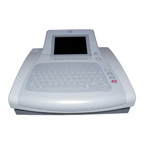
System Overview The MAC™ 3500 resting ECG analysis system is a 12-lead, 12-channel system with a 6.5 inch (165 mm) diagonal display, active patient cable, and battery operation. There are also options for communication capabilities Hardware Description This section identifies the key components of the MAC system hardware. Familiarize yourself with these components, their location, and their use before attempting to use the equipment. -
Page 30: Side View
System Overview Side View Name Description ECG signal input connector Connects to the acquisition module. KISS pump connector Optional feature that connects to the KISS pump. LAN port Connects to a local area network (LAN) via a cable. LEDs provide information about the connection status. - Page 31 Name Description Connects to an optional card reader, bar code reader, or PS/2 keyboard for entering patient information. Connects to a GE KISS pump. When using the exercise option, connects to a T2000 treadmill or external blood pressure device. NOTE: Ergoline bicycle ergometers must be connected to both this port and the ANA/TTL port.
-
Page 32: Internal View
System Overview Internal View Name Description Latch Opens the unit for access to the battery and paper tray. Also contains two indicator lights: a green light indicates when the unit is attached to AC power and an amber light indicates the battery is charging. Battery Supplies power when unit is not connected to AC power. -
Page 33: Trolley Assembly
Trolley Assembly For instructions to assembly the trolley, see Modular MAC Trolley, 2056914–001. 2046275-019H MAC™ 3500... - Page 34 Trolley Assembly MAC™ 3500 2046275-019H...
-
Page 35: Troubleshooting
Troubleshooting This chapter provides general and specific information to help you isolate service problems. It consists of the following sections: • “Diagrams” • “General Fault Isolation” • “Diagnostic Tests” • “Equipment Problems” • “System Errors” • “Frequently Asked Questions” • “Input and Output Connectors”... -
Page 36: Pcb_Diagrams
Troubleshooting PCB_Diagrams The following illustrations diagram the structure of the PCB, the connections to and from the PCB, and the connections to the supported display assemblies. PCB Block Diagram MAC™ 3500 2046275-019H... - Page 37 Troubleshooting PCB Connections Diagram Display Connection Details Diagram 2046275-019H MAC™ 3500...
-
Page 38: Lvds/Led Display Assembly Diagram
LVDS/LED Display Assembly Diagram The following illustration diagrams the connections for the LVDS/LED display assembly (2026799–002), and the table that follows it identifies those connections. LVDS/LED Display Assembly Connections Item GE Part Number Description 2024701-001 ASSY DISPLAY CABLE MAC3500 (CMOS) 2062075-001... -
Page 39: Power-Up Self-Test
Troubleshooting Power-Up Self-Test Power up the device. During power-up, the system conducts a series of internal tests, as shown in the following diagram. If the start screen opens normally, all circuits passed their tests. If the start screen does not open normally, or if error messages were displayed during start up, all circuits did not pass their tests. -
Page 40: Visual Inspection
Troubleshooting Verify the following: • The power cord is connected to both the AC Mains on the back of the device and an AC outlet. • The green AC power light is lit, indicating the device is receiving power from the AC outlet. -
Page 41: Diagnostic Tests
Troubleshooting Area Look for the following problems Circuit boards • Moisture, dust, or debris (above and below) • Missing components • Loosely seated components • Burn damage or overheated smell • Improperly seated PCB • Solder problems: cracks, splashes on board, incomplete feedthrough, prior modifications, repairs Ground wires/wiring •... -
Page 42: Loading System Diagnostic Tests
Troubleshooting Loading System Diagnostic Tests Use the following procedure to access the system diagnostic tests. From the resting ECG screen, select Main Menu > More > System Setup. You are prompted for the service password. Type the password and press Enter. The System Setup menu opens. -
Page 43: Display Tests
Type a new password in the System password field and press Enter. Note the new password for future reference. Select Save Setup > To system. Contact GE Healthcare Technical Support and provide them with the customer information, device serial number, and password. Display Tests The system provides two display tests: •... -
Page 44: Speaker Test
Troubleshooting Press any key to display the next test pattern. One of two test patterns is displayed. • If the system color option is enabled, a 32–color test palette is displayed. • If the system color option is not enabled, various grey scale test patterns are displayed. -
Page 45: Writer Tests
Troubleshooting NOTE: The stress keys (1) are available only on the MAC 5500 ST keyboard. These keys will not be available for testing on any other keyboard or system. Pressing the Leads key (2) displays the word Copy if the key is functioning properly. - Page 46 Troubleshooting Skewed or crushed paper indicates a problem with paper cueing. • The triangles and diagonal lines printed on the paper are straight and uniform. Curved or wavering lines could indicate a problem with paper speed, tracking, or cueing. • The lines printed on the paper are clean and unbroken. Gaps, smears, blotches, and other defects indicate a problem with the print head quality.
- Page 47 Troubleshooting After printing the three test patterns, verify the following: • Each test pattern is 250 mm ± 5mm long from start to finish. Use the grids located on the top and bottom of each page for reference. If the printout is out of range, the paper speed is too fast or too slow.
- Page 48 Troubleshooting After the printout completes, check the following: • The pattern begins approximately 13–14 mm from the end of the page. A larger or smaller gap between the end of the page and the pattern could indicate a problem with paper cueing. •...
-
Page 49: Battery Tests
Troubleshooting Continuously Run Out Paper The Continuously Run Out Paper test ejects paper until the paper tray is empty. Manufacturing uses this test to determine how well the unit self-corrects tracking problems. Battery Tests Use the battery tests to monitor the battery's status, discharge rate, and charge rate. Test results are stored in memory and can be printed out. - Page 50 Troubleshooting Turn the AC power to the unit OFF Unplug the unit from AC (mains) power and select OK. Select Battery Discharge Test. The battery begins to discharge. When the battery has fully discharged, the unit will shut off. Reconnect the unit to AC power and turn the unit on. Do one of the following: •...
-
Page 51: Communication Tests
Troubleshooting Monitored information is written to internal memory and includes: • Charge rate (in mAH) • Battery temperature • Battery charge status • To print the test results, proceed to “Print Charge/Discharge Test Results” on page Print Charge/Discharge Test Results The Print Charge/Discharge Test Results prints the results of the Battery Charge Test (page 50) and Battery Discharge Test... - Page 52 Troubleshooting External Modem Test The External Modem Test verifies that the COM2 port can successfully communicate with an optional external modem. NOTE: Although COM 2 is also used to connect the wireless client bridge, this test is designed to check a modem only. It cannot be used to test the wireless client bridge.
-
Page 53: Acquisition Module Test
Troubleshooting Ethernet Module Test The Ethernet Module Test verifies the system can communicate via the Ethernet connection. Select Ethernet Module Test. The Ethernet Module Interrogation window opens and displays one of the following: • If the system can communicate via the Ethernet, the test returns and displays the device IP address, subnet mask, and MAC address information. -
Page 54: Analog I/O Tests
1) Acquisition Board Noise Floor; 2) Acquisition Board Communication Test; 3) Acquisition Board Software Version NOTE: The Button Pressed test does not apply to the MAC 3500. Analog I/O Tests The Analog I/O Tests check the system's ANA/TTL connection. If any of the tests fail, it may indicate the CPU board needs to be replaced. -
Page 55: Floppy Drive Tests
When the test is complete, Passed or Failed will be displayed on the screen, depending on the results. Floppy Drive Tests NOTE: The Floppy Drive Test is not applicable for MAC 5500 or MAC 3500 systems. 2046275-019H MAC™ 3500... -
Page 56: Internal Memory Tests
Troubleshooting Internal Memory Tests The Internal Memory Tests check bad blocks and the amount of free memory in the device's internal storage. Select Internal Memory Tests from the System Diagnostics Main Menu. The number of bad blocks and the amount of free memory is displayed. Press any key to continue. -
Page 57: Equipment Problems
The following table lists symptoms of some common system errors you may experience, identifies possible causes for those errors, and suggests some corrective actions you can take. If the corrective actions do not resolve the errors, contact GE Healthcare Technical Support or an authorized third-party service provider. Symptom... -
Page 58: Frequently Asked Questions
Troubleshooting Symptom Cause Solution The system shuts down when The battery is completely Connect the system to an AC wall operating from battery power. discharged, or the Automatic outlet to charge the battery, or Shutdown feature is enabled. power on the system. “X”... -
Page 59: System Setup
This capacity diminishes as the battery ages. NOTE: GE Healthcare recommends the device be plugged into an AC outlet whenever it is not in use. System Setup The following FAQs relate to the setup of the device. For more detailed information on any of these questions, refer to the operator's manual. -
Page 60: Clinical
Troubleshooting How do I change the questions displayed when entering patient data? Use the following procedure to customize the Patient Questions, which are asked when starting a test. Select System Setup > Basic System > Patient Questions. Define the patient questions and their response types. These questions will be asked when you enter patient data for a new test. -
Page 61: Transmission
Troubleshooting if you edit the interpretation, the data will not be saved unless the record is confirmed at the MAC 5500. The record is transmitted to the MUSE system as a confirmed record as well. Do I have to enter all the data on the Patient Data screen? In System Setup >... -
Page 62: Com1 (Com3/4) Pins (J3)
Troubleshooting COM1 (COM3/4) Pins (J3) COM1 (COM3/4) Pins (J3) Name Diagram COM3 TxD COM3 RxD COM1 TxD Ground COM1 RxD COM4 TxD +12V COM4 RxD COM2 Pins (J5) COM2 Pins (J5) Names Diagram Ground +12V Analog Pins (J6) Analog Pins (J6) Names Diagram +12V... -
Page 63: Ext. Vid. Pins (J7)
Troubleshooting EXT. VID. Pins (J7) EXT. VID. Pins (J7) Names Diagram Red Video Green Video Blue Video Ground Ground Ground Ground Ground Ground Ground Horizontal Sync Vertical Sync CPU PCB Input/Output Signals The following sections detail the input/output signals for the CPU PCB. The pin-by-pin descriptions identify the associated signal names. -
Page 64: Lcd Backlight (J4)
Troubleshooting LCD Backlight (J4) LCD Backlight (J4) Signal 12V Power 12V Power 12V Power Ground Ground Brightness select Backlight enable Ground Ground Keyboard (J8) Keyboard (J8) Signal Resistor ground Ground Ground Ground Ground Sense4 Sense2 Sense1 Sense0 Sense3 Sense5 Sense6 Sense7 Drive0 Drive1... -
Page 65: Lcd (J10)
Troubleshooting Keyboard (J8) (cont'd.) Signal Drive5 Drive6 Drive7 Drive8 Drive9 Drive10 LCD (J10) LCD (J10) Signal Ground Clock Hsync Vsync Ground R0 (LSB) R5 (MSB) Ground G0 (LSB) G5 (MSB) Ground B0 (LSB) B5 (MSB) 2046275-019H MAC™ 3500... -
Page 66: Power Supply/Motor (J11)
Troubleshooting LCD (J10) (cont'd.) Signal Ground Data enable 3V Power 3V Power Power Supply/Motor (J11) Power Supply/Motor (J11) Signal Motor Encoder B 5V Power Motor A Motor Encoder A Ground Motor B 28V Power Ground Battery Charge LED 28V Power Ground Door open detect Ground... -
Page 67: Floppy Disk Drive (J13)
Troubleshooting Thermal Printer (J12) (cont'd.) Signal Thermal printer power Ground Ground Ground Ground Ground Ground Ground Cue sense 5V Main power Ground Data strobe Data strobe Data strobe Data strobe Data load Data clock Print head temperature Pixel Data Floppy Disk Drive (J13) Floppy Disk Drive (J13) Signal 5V Power... -
Page 68: Acquisition Module (J14)
Troubleshooting Floppy Disk Drive (J13) (cont'd.) Signal Direction Step Ground Write data Ground Write gate Ground Track 0 Ground Write protect Ground Read data Ground Head select Acquisition Module (J14) Acquisition Module (J14) Signal Power Ground TX+ (RS485) TX- (RS485) RX+ (RS485) RX- (RS485) KISS Pump (J19) -
Page 69: Acquisition Module (J20)
Troubleshooting KISS Pump (J19) (cont'd.) Signal Acquisition Module (J20) Acquisition Module (J20) Signal TX- (RS485) TX+ (RS485) RX- (RS485) RX+ (RS485) Power 12V LCD Backlight (J23) LCD Backlight (J23) Signal Power 5V DC Power 5V DC Relay Port 1 (Resistance) Relay Port 2 (Resistance) 2046275-019H MAC™... - Page 70 Troubleshooting MAC™ 3500 2046275-019H...
-
Page 71: Maintenance
Maintenance Regular maintenance, irrespective of usage, is essential to ensure that the equipment will always be functional when required. But even with a regular maintenance regime, the device may eventually need servicing. Therefore, this chapter describes both typical maintenance procedures and standard service procedures. WARNING: MAINTENANCE —... -
Page 72: System Cleaning And Inspection
• Missing or illegible safety-related markings and labels If the power cord shows any of these signs, remove it from service and replace it with the appropriate GE Healthcare replacement part. Repairs or modifications to the power cord are not allowed. - Page 73 Maintenance Cleaning and Disinfecting the Surfaces Proper cleaning and disinfecting prolongs the life of the product. Failure to use the proper cleaning solutions or to follow proper procedures can result in the following: • Damage or corrosion • Product discoloration •...
-
Page 74: Cleaning The Interior
Maintenance • Never autoclave or steam clean the device, cables, or leadwires. • Do not use until thoroughly dry. Cleaning the Interior • Check for dust buildup on the surfaces of the interior circuit boards, components, and power supply. • Use commercially available compressed air to blow away the accumulated dust. Follow the manufacturer's directions. -
Page 75: Setting The Correct Paper Size
Maintenance Setting the Correct Paper Size The MAC system can accommodate standard (US Letter) and A4 fanfold thermal ECG paper. To ensure that the paper feeds correctly, you must adjust the paper guide Open the MAC writer drawer. To set the tray for A4 paper, slide the paper guide toward the rear of the device. To set the tray for standard (US Letter) paper, slide the guide toward the front of the device. -
Page 76: Loading The Paper
Maintenance Loading the Paper Use the following instructions to load paper into the MAC system. Refer to the following illustration. Open the writer drawer. Place the pad of paper with the holes on the left. Advance the first sheet of paper. Close the writer drawer securely. -
Page 77: Charging The Battery
Maintenance Charging the Battery A fully charged battery ensures that the MAC system will operate without being connected to an AC outlet. The MAC system's battery should be charged at the following times: • Before initial use • Between acquisitions •... -
Page 78: Conditioning The Battery
A deep discharge cycle occurs when the battery is discharged until the system shuts down and then recharged until it is full. GE Healthcare recommends one deep discharge cycle once every three months, but does not recommend over-exercising the battery with multiple deep discharge cycles. -
Page 79: Checking Electrical Safety
Maintenance WARNING: BATTERY PACK DISPOSAL — Do NOT dispose of the battery pack by fire or burning. Follow local environmental guidelines concerning disposal and recycling. WARNING: CHEMICAL BURN — If battery fluid contacts your skin, eyes, or clothing, immediately wash the area with clean water and see a doctor. Checking Electrical Safety The device should be checked annually for current leakage and ground continuity. -
Page 80: Removing The Device From The Trolley
Maintenance • Remove the battery. • Remove the chart paper. • Take precautions against electromagnetic discharge damage. Removing the Device from the Trolley If your MAC system is mounted on a trolley, you must remove it from the trolley before servicing it. - Page 81 Maintenance Type-S Trolley To remove the device from the Type-S trolley, perform the steps shown in the following illustration. Modular MAC Trolley To remove the device from the modular MAC trolley, perform the following steps. Remove the bolts connecting the mounting tray to the trolley top. Tilt the rear of the device and mounting tray to a 30°...
-
Page 82: Replacing The Power Supply
Maintenance Replacing the Power Supply Use the following procedure to replace the power supply. NOTE: A #10 Torx driver is required for this procedure. Turn the unit over so the bottom side is facing up. Using a #10 Torx driver, remove the screws (1) holding the power supply in place. Lift the power supply to expose the ground wire (2) and wiring harness (3). - Page 83 Maintenance Remove the two fasteners that secure the display panel cover at the back of the unit and remove the display cover. Remove the two fasteners securing the top of the keypad. 2046275-019H MAC™ 3500...
-
Page 84: Replacing The Top Cover/Keyboard Assembly
Maintenance Pull up on the keypad assembly to release it from the top cover. You will hear snapping sounds as each of the eight plastic standoffs is released. NOTE: The eight plastic standoffs should remain with the keypad. However, if any remain in the top cover, use a set of small pliers to extract them from the cover. - Page 85 Maintenance Remove the five Torx fasteners from inside the paper tray shown in the following figure. Remove the two fasteners that secure the display panel cover at the back of the unit and then remove the display cover. Remove the two fasteners holding the two ground wires on either side of the display.
-
Page 86: Replacing The Display Assembly
Maintenance Disconnect the following cables from the main PCB board: • Blue ribbon cable • Display light cable • Keyboard ribbon cable NOTE: Do not force the cable from its connector. Raise both ends of the plastic locking bar (shown in the following figure) and gently rock the ribbon cable free from the connector. - Page 87 Maintenance Remove the two fasteners holding the two ground wires on either side of the display. Pivot up the display to access the cable connections on the main PCB. NOTE: If a KISS pump is installed, it must be removed to access the display panel connectors from the main board.
-
Page 88: Replacing The Lvds Converter Board
Maintenance Replacing the LVDS Converter Board Use the following procedure to replace the LVDS converter board required by the AUO LCD display (P/N 2062075–001). Remove the display assembly from the device. “Replacing the Display Assembly” on page 86 for instructions. Disconnect all cables from the LVDS converter board. -
Page 89: Replacing The Optional Kiss Pump
Maintenance Replacing the Optional KISS Pump Use the following procedure to replace the optional KISS pump. Remove the battery as described in “Replacing the Battery” on page Remove the two fasteners that secure the display panel cover at the back of the unit and remove the display cover. -
Page 90: Replacing The Comm Board
Maintenance Using a Phillips screw driver, remove the two screws holding the acquisition connector bracket (1) to the acquisition board. Remove the three fasteners securing the acquisition board to its mounting bracket. Pull up on the cable connector to disconnect it from the main CPU board. Remove the acquisition board from the unit. -
Page 91: Replacing The Cpu Board
Maintenance Grasp the side edges of the COMM board. Rock the board side to side in the slot as you pull it out along its rails. Insert the new communications board, sliding it onto the rails until it is seated in place. - Page 92 Maintenance Each task is described in the following sections. NOTE: Before you begin, save the current System Setup to an SD card and print a System Setup report. This will be used to restore the system setups after replacement of the CPU board. Removing the CPU Board Use the following procedure to remove the CPU board.
- Page 93 Maintenance Disconnect the battery cable (J2), the power cable (J11), and the printhead cable (J12) from the main CPU board. Remove the nine Torx fasteners (2) securing the CPU board. Lift the CPU board from the lower frame. Reassembling the CPU Board After removing the CPU board, use the following procedures to reassemble the new CPU board in the MAC device.
- Page 94 Maintenance Installing the software The MAC software is provided on an SD card. NOTE: Before applying a software update, do the following: • Confirm the update is compatible with the main board in your device. • Updates with boot code version B4 or higher cannot be applied to devices with the –007 main board (P/N 801212-007).
- Page 95 Maintenance Do one of the following: • To cancel the update to the boot code, press any key other than Enter. The following messages are displayed: Boot code not updated. Can update later from service setup. • To update the boot code, press Enter. The following messages are displayed: Programming Primary Boot Programming Over...
- Page 96 Maintenance Connect the device to AC power. Keep the device connected to AC power during the software update. Insert the SD card with the required application software. Before inserting the SD card, confirm that the dummy file update.com is located in the card’s root directory.
- Page 97 Maintenance This is the number that was used when the option codes for this system were generated. The number entered here must match the serial number on the system label. • Printhead resistance This number can be found on the printhead label. •...
-
Page 98: Replacing The Printhead
Maintenance Restoring options Use the following procedure to restore the system options that had been installed on the CPU board that was removed. These options are printed on a label located on the bottom of the paper tray, as shown in the following illustration. NOTE: Use the activator codes shown on the label on your system. - Page 99 Maintenance Remove the E-ring from the steel pin that holds the printhead assembly in place. Slide the steel pin out of the assembly. Set aside the steel pin (1), the three plastic washers (2), the compression spring (3), and the E—ring (4) for the printhead reassembly. The relative order of each component is shown in the following figure.
-
Page 100: Replacing The Writer Roller/Carriage Assembly
Maintenance Replacing the Writer Roller/Carriage Assembly Use the following procedure to replace the writer roller/carriage assembly. Remove the power supply following the procedure described in “Replacing the Power Supply” on page Inside the power supply compartment, disconnect the cable connected to the writer assembly. -
Page 101: Functional Checkouts
Maintenance Insert a paper clip into the pin hole (3) until the cable latch is fully depressed and remove the cable (4). Insert the new cable into the handle of the barcode reader until it snaps into place. Fold the label into its original position. Perform all applicable functional checkouts. - Page 102 Maintenance To use the tables, locate the relevant FRU or task in the first column and note the required Tools, Visual Inspections, and Checkout Procedure(s) for the item. Then locate the corresponding instructions in the sections following the tables. NOTE: The FRU checkout procedure for any listed FRU also applies to its internal PCBs and components.
-
Page 103: Tools
Maintenance Option Repairs (cont'd.) FRU / Option Tools Visual Inspection Checkout Procedure(s) Barcode Reader 1, 2, 5 1, 3, 8 Mag Card Reader 1, 2, 5 1, 3 Non-FRU Repairs FRU Description Tools Visual Inspection Checkout Procedure(s) 1, 3, 4 No Parts Replaced 1, 5 1, 2, 3, 4, 5... - Page 104 Maintenance Operational Checks Power-up self-test passed? Simulated printed rhythm strip successful? Simulated printed ECG successful? Simulated ECG stored on media successful? Simulated ECG data transmitted successfully? Exercise device successfully communicates with device? Blood pressure monitor successfully communicates with device? Barcode reader successfully communicates with device? Trolley casters lock successfully? Diagnostic Tests Battery Status Test meets Battery Current expectation?
- Page 105 Maintenance Electrical Safety Checks Current leakage and ground continuity test results meet requirements? Perform electrical safety checks when indicated. All indicated electrical safety checks require a pass/fail indication for steps performed. Record the measurement values in your debrief. Electrical Safety Checks Step UUT —...
- Page 106 Maintenance MAC™ 3500 2046275-019H...
-
Page 107: Parts List
Parts List The Field Replaceable Unit lists in this chapter supply enough detail for you to order parts for the assemblies, standalone FRUs, and FRU kits considered field serviceable. Only assemblies, items, and kits with part numbers are considered FRUs. 2046275-019H MAC™... -
Page 108: Upper-Level Assemblies
Parts List Upper-Level Assemblies MAC™ 3500 2046275-019H... - Page 109 Parts List 2046275-019H MAC™ 3500...
- Page 110 Parts List MAC™ 3500 2046275-019H...
- Page 111 Parts List 2046275-019H MAC™ 3500...
- Page 112 PRINTER THERMAL MAC3500 “Universal Writer Kit (P/N 2031810-002)” on page 119 details. BTN 3500 WRITER Not available as a standalone FRU. See “MAC 3500 Plastics Kit (P/N 2030898–001)” on page 128. LIGHT PIPE MAC3500 Not available as a standalone FRU. See “MAC 3500 Plastics Kit (P/N...
- Page 113 Part Number 801212-008 PCB ASSY MAC CPU ROHS This board works on MAC 3500 and MAC 5500 devices running MAC software versions 9D and 10B or later. It does not work on MAC 5000 devices. It is loaded with factory software that is not intended for patient use.
- Page 114 See“MAC 3500 Plastics Kit (P/N 2030898–001)” on page 128. 2026799-002 ASSY DISPLAY — MAC3500 AUO LVDS-LED “MAC 3500 Display Assembly (P/N 2026799-002)” on page 116 for detailed information. 2022882-002 PUMP KISS ASSY MAC 3500 “MAC 3500 KISS Pump Assembly (P/N 2022882-002)” on page for detailed information.
- Page 115 Item Description Part Number SPACER MALE/FEMALE M3 X 10 HEX Not available as a standalone FRU. See “Hardware Kit for MAC 3500 (P/N 2030869–001)” on page 127. FITTING PNEU 1/8" QUICK FEMALE Not available as a standalone FRU. See “MAC 3500 KISS Pump Hardware Kit (P/N 2030872-002)”...
-
Page 116: Mac 3500 Display Assembly (P/N 2026799-002)
Parts List MAC 3500 Display Assembly (P/N 2026799-002) Except where noted, items with no part number are not available as standalone FRUs; they are available only with the full assembly. MAC 3500 Display Assembly (P/N 2026799-002) Item Part Number Description... - Page 117 Parts List MAC 3500 Display Assembly (P/N 2026799-002) (cont'd.) Item Description Part Number 2034900-003 MAC3500 PWR CABLE MAIN BOARD TO LVDS Available only in a FRU kit. See “Harness Kit for MAC 3500 (P/N 2030871–002)” on page 132 for more information.
-
Page 118: Mac 3500 Kiss Pump Assembly (P/N 2022882-002)
MAC 3500 KISS Pump Assembly (P/N 2022882-002) Except where noted, items with no part number are not available as standalone FRUs; they are available only with the full assembly. MAC 3500 KISS Pump Assembly (P/N 2022882-002) Item Description Part Number... -
Page 119: Universal Writer Kit (P/N 2031810-002)
Parts List Universal Writer Kit (P/N 2031810-002) Except where noted, items are not available as standalone FRUs; they are available only with the full assembly. Universal Writer Kit (P/N 2031810-002) Item Description BUTTON BATTERY MAC SERIES M3 X 8MM TORX SEMS SPRING BATTERY MAC SERIES SPRING, BAT. -
Page 120: Thermal Writer Assembly (P/N 421108-009)
Parts List Thermal Writer Assembly (P/N 421108-009) MAC™ 3500 2046275-019H... - Page 121 BASE, WRITER MAC SERIES 422396-003 ASSY ROLLER MAC SERIES WRITER SPACER PAPER MAC SERIES M3 X 8MM TORX SEMS Not available as a standalone FRU. See “Hardware Kit for MAC 3500 (P/N 2030869–001)” on page 127. CLIP, INT. STAR 416015-001 SHOCK CYLINDER...
-
Page 122: Keyboards
Parts List Keyboards MAC 3500 Keyboard (English) Keyboards Part Number Description 2022885-001 KYBD MAC 3500 2022885-002 KYBD GER MAC3500 2022885-003 KYBD FRE MAC3500 2022885-004 KYBD SPA MAC3500 2022885-005 KYBD SWE MAC3500 2022885-006 KYBD ITA MAC3500 2022885-007 KYBD JAP MAC3500 2022885-008... -
Page 123: Bar Code Scanner
Parts List Bar Code Scanner Bar Code Scanner Part Number Description 2031240-001 KIT 2D BARCODE IMAGER MAC5000 ENGLISH 2031240-002 KIT 2D BARCODE IMAGER MAC5000 GERMAN 2031240-003 KIT 2D BARCODE IMAGER MAC5000 FRENCH 2031240-004 KIT 2D BARCODE IMAGER MAC5000 SPANISH 2031240-005 KIT 2D BARCODE IMAGER MAC5000 SWEDISH 2031240-006 KIT 2D BARCODE IMAGER MAC5000 ITALIAN... -
Page 124: Modems
Parts List Modems Modems Part Number Description 2005264-001 KIT MAC 5000 EXT MODEM 56K US 2005264-002 KIT MAC 5000 GLOBAL EXT MODEM 56K 2005264-003 KIT MAC 5000 EXT MODEM 56K ASTL 2005264-004 KIT MAC 5000 EXT MODEM 56K CZEC 2005264-005 KIT MAC 5000 GLOBAL EXT MODEM 56K 2005264-006 KIT MAC 5000 EXT MODEM 56K JAP... -
Page 125: Power Cords
Parts List Power Cords Power Cords Part Number Description 401855-001 PWR CRD CONT EURO 10A 250V 8FT 401855-002 PWR CORD BRITISH 10A 250V 8FT 401855-003 PWR CORD ITALIAN 10A 250V 8FT 401855-004 PWR CORD ISRAELI 10A 250V 8FT 405535-006 PWR SPLY CRD RA HOSP GRD 13A 125V 10FT 401855-007 PWR CORD SWISS 10A 250V 8FT 401855-008... - Page 126 Parts List MAC™ 3500 2046275-019H...
-
Page 127: Hardware Kit For Mac 3500 (P/N 2030869-001)
Parts List Hardware Kit for MAC 3500 (P/N 2030869–001) Items are not available as standalone FRUs; they are available only with the full kit. Items are not drawn to relative scale. Figures are provided for reference only. Hardware Kit for MAC 3500 (P/N 2030869–001) -
Page 128: Mac 3500 Plastics Kit (P/N 2030898-001)
Parts List MAC 3500 Plastics Kit (P/N 2030898–001) MAC™ 3500 2046275-019H... - Page 129 Parts List Items are not available as standalone FRUs; they are available only with the full kit. Items are not drawn to relative scale. Figures are provided for reference only. MAC 3500 Plastics Kit (P/N 2030898–001) Item Description BTN 3500 WRITER...
-
Page 130: Mac 3500 Top Cover Kit (P/N 2030899-001)
Parts List MAC 3500 Top Cover Kit (P/N 2030899–001) MAC™ 3500 2046275-019H... - Page 131 Parts List Items are not available as standalone FRUs; they are available only with the full kit. Items are not drawn to relative scale. Figures are provided for reference only. MAC 3500 Top Cover Kit (P/N 2030899–001) Item Description PLASTIC TOP COVER...
-
Page 132: Harness Kit For Mac 3500 (P/N 2030871-002)
Parts List Harness Kit for MAC 3500 (P/N 2030871–002) Harness Kit for MAC 3500 (P/N 2030871–002) Item Description ASSY MAC3500 BACKLIT CABLE–AUO MAC3500 LCD CABLE Assembly Display Cable MAC3500 MAC3500 Power Cable Main Board to LVDS HARN LCD DISPLAY GROUND FLEX CKT ASSY CAM MAC™... -
Page 133: Mac 3500 Kiss Pump Hardware Kit (P/N 2030872-002)
Parts List MAC 3500 KISS Pump Hardware Kit (P/N 2030872-002) MAC 3500 KISS Pump Hardware Kit (P/N 2030872-002) Item Description ASSY WIRE SET KISS PUMP MAC3500 not shown BRACKET KISS PUMP MAC3500 NUT LOCK PLUG LUER MALE CONNECTOR LUER FEMALE FITTING PNEU 1/8"... -
Page 134: Secure Digital (Sd) Cards (External Storage)
Parts List Secure Digital (SD) Cards (External Storage) SD Cards Part Number Description 2027268-004 CARD SECURE DIGITAL - 512MB 2027268-005 CARD SECURE DIGITAL - 2GB Only MAC systems running version 10 software and systems upgraded to version 10 software support SD High Capacity (SDHC) cards. -
Page 135: Technical Specifications
12-leadwire acquisition with NEHB configuration. Processing Processing Specifications Item Description ECG Interpretation GE Marquette 12SL ECG Analysis Program for Adults and Pediatrics Computerized 12-lead analysis measurements ECG storage 50 ECGs in internal memory External archiving Optional secure digital card supports up to a maximum of 50 ECGs... -
Page 136: Display
Technical Specifications Processing Specifications (cont'd.) Item Description <10 μA Patient leakage Pace detect Orthogonal LA, LL, and V6; 750 μV @ 50 μs Special acquisition Disconnected lead detection, electrode impedance, excessive, AC functions noise, baseline wander, and muscle tremor messages Heart rate meter 30 to 300 BPM ±10% or 5 BPM, whichever is greater. -
Page 137: Electrical
Technical Specifications Electrical Electrical Specifications Item Description Power Supply AC or battery operation Voltage 100V -240V +/- 10% tolerance Current 0.5A @ 115 VAC, 0.3A @ 240 VAC, typical Frequency 50–60 Hz, ±10% Battery Type User replaceable, 18V @ 3.5 AH ±10%, rechargeable NiMH pack Battery Capacity 100 single-page reports (typical) or 6 hours continuous operation (without printing) -
Page 138: Bar Code Reader
Technical Specifications Magnetic Card Reader Specifications (cont'd.) Item Description 10% to 90% Humidity Agency conformance: Complies with FCC Class A. Bar Code Reader Bar Code Reader Specifications Item Description Symbologies Code 39 (extended), PDF-417, Code 128, Data Matrix, Interleaved 2 of 5. Width 2.02 in. -
Page 139: Safety
Liquids Handling of Disposable Use only parts and accessories manufactured or recommended Supplies and Other by GE Medical Systems Information Technologies. Follow Consumables manufacturer’s instructions for use for disposable/consumable products. Follow local environmental guidelines concerning the disposal of hazardous materials. - Page 140 Technical Specifications Item Description Maintenance Daily visual inspection and routine cleaning (if needed) performed Frequency by user. Use a commercially available, industrial strength disinfectant cleaner on any part of the equipment (other than electrodes) which comes into direct contact with the patient. Every six months routine maintenance checks and test procedures performed by qualified technical personnel.
-
Page 141: Software/Hardware Compatibility
801212–006, 801212–007, and 801212–008 circuit boards. However, the components used to construct the display assemblies are not interchangeable. Compatible Display Assemblies Display Type (10.5”) Part Number Description Make Model Type 2026799–001 —18D Display Assembly MAC 3500 CCFL/CMOS Display Assembly MAC 3500 2026799–002 LED/LVDS AUO LVDS-LED 2046275-019H MAC™ 3500... -
Page 142: Circuit Board Compatibility Matrix
Software/Hardware Compatibility Circuit Board Compatibility Matrix Not all supported software versions are compatible with all CPU/Comm board combinations. You must know which software versions are compatible with which CPU and Comm boards before you replace either board or upgrade your software. The following table identifies which software versions are compatible with which CPU/Comm board combinations. -
Page 143: Supported Software Update Paths
Software/Hardware Compatibility Supported Software Update Paths The following table identifies the supported software update paths for each supported main board. Attempting any unlisted update could result in issues either with the update process itself or with the device after the update is complete. Supported Software Update Paths Update Main... - Page 144 Software/Hardware Compatibility MAC™ 3500 2046275-019H...
-
Page 145: Electromagnetic Compatibility
Electromagnetic Compatibility Changes or modification to this system not expressly approved by GE Healthcare could cause EMC issues with this or other equipment. This system is designed and tested to comply with applicable regulation regarding EMC and needs to be installed and put into service according to the following EMC information. -
Page 146: Guidance And Manufacturer's Declaration - Electromagnetic Immunity
Electromagnetic Compatibility Guidance and Manufacturer's Declaration - Electromagnetic Immunity The device described in this manual is intended for use in the electromagnetic environment specified below. It is the responsibility of the customer or user to ensure that the device is used in such an environment. Immunity Test EN 60601 Test Level Compliance Level... - Page 147 Electromagnetic Compatibility Immunity Test EN 60601 Test Level Compliance Level Electromagnetic Environment – Guidance Portable and mobile RF communications equipment should not be used closer to any part of the equipment, including cables, than the recommended separation distance calculated from the equation applicable to the frequency of the transmitter.
-
Page 148: Recommended Separation Distances
Electromagnetic Compatibility NOTE: These guidelines may not apply in all situations. Electromagnetic propagation is affected by reflection from structures, objects, and people. Field strengths from fixed transmitters, such as base stations for radio (cellular/cordless) telephones and land mobile radio, AM and FM radio broadcast, and TV broadcast cannot be predicted theoretically with accuracy. -
Page 149: Compliant Cables And Accessories
The following table lists cables, transducers, and other applicable accessories with which GE Healthcare claims EMC compliance. NOTE: Any supplied accessories that do not affect EMC compliance are not included. - Page 150 Electromagnetic Compatibility MAC™ 3500 2046275-019H...
- Page 152 GE Medical Systems Information Technologies, Inc. 8200 West Tower Avenue Milwaukee, WI 53223 USA Tel: +1 414 355 5000 +1 800 558 5120 (US Only) GE Medical Systems Information Technologies, Inc., a General Electric Company, going to market as GE Healthcare. www.gehealthcare.com...
Need help?
Do you have a question about the MAC 3500 and is the answer not in the manual?
Questions and answers