Table of Contents
Advertisement
Quick Links
Advertisement
Table of Contents

Related Manuals for GE MAC 600 SPY


Summary of Contents for GE MAC 600 SPY
- Page 1 GE Healthcare ™ Service Manual Product Code SPY 2047426-002 Revision G...
- Page 2 Marquette, MUSE, MAC, MULTI-LINK, Hookup Advisor, 12SL, Mactrode, and Baby MAC are trademarks owned by GE Medical Systems Information Technologies, a General Electric Company going to market as GE Healthcare. All other marks are owned by their respective owners.
-
Page 3: Table Of Contents
Contents Introduction ........1-1 Manual Information ..........1-2 Revision History . - Page 4 Testing the Display ..........3-7 Testing the Buzzer .
- Page 5 Ground Resistance Test ......... . . 4-24 Leakage Current Tests .
- Page 6 FRU Battery ..........5-23 FRU Software Update - SD Card .
-
Page 7: Introduction
Introduction Revision G 2047426-002... -
Page 8: Manual Information
Introduction: Manual Information Manual Information Revision History Each page of the document has the document part number and revision letter at the bottom of the page. The revision letter identifies the document’s update level. The revision history of this document is summarized in the following table. -
Page 9: Contraindications
Introduction: Manual Information Contraindications This system is not intended for use as a vital signs physiological monitor or for use during patient transport. This device is not intended for use with high-frequency surgical units. Disconnect the device from the patient before using the high- frequency surgical units. -
Page 10: Safety Messages
U.S. Federal law restricts this device for sale by or on the order of a physician. Responsibility of the Manufacturer GE Healthcare is responsible for the effects of safety, reliability, and performance only if: Assembly operations, extensions, readjustments, modifications, or ... -
Page 11: General
It is the user’s responsibility to report the need for service to GE Healthcare or an authorized agent. Equipment Identification Every GE Healthcare device has a unique serial number. The serial number appears on the device label and is formatted as shown. Revision G... -
Page 12: Serial Number Label Format
Introduction: Service Information Table 1-4. Equipment Identification Item Description Product label Serial number label Serial Number Label Format The serial number label is located on the bottom cover beside the product label. Table 1-5. Serial Number Label Details Item Description Product part number Manufacture date in YYYY-MM format Serial number barcode... -
Page 13: Serial Number Format
Introduction: Service Information Serial Number Format The serial number appears as follows: Table 1-6. Serial Number Format Item Description The product code for MAC 600 system is SPY Year Manufactured (00-99) 00 = 2000 01 = 2001 02 = 2002 Fiscal Week Manufactured Production Sequence Number Manufacturing Site... -
Page 14: Product Label
Introduction: Service Information Product Label The product label is located on the back of the device next to the external power input. NOTE Your product label may vary. Table 1-7. Product Label Item Description Product name (MAC 600) Manufacturing Site Input power rating Symbols See the “MAC 600 Operator’s Manual”... - Page 15 Introduction: Service Information For your notes Revision G 2047426-002...
- Page 16 Introduction: Service Information 1-10 Revision G 2047426-002...
-
Page 17: Equipment Overview
Equipment Overview Revision G 2047426-002... -
Page 18: General Description
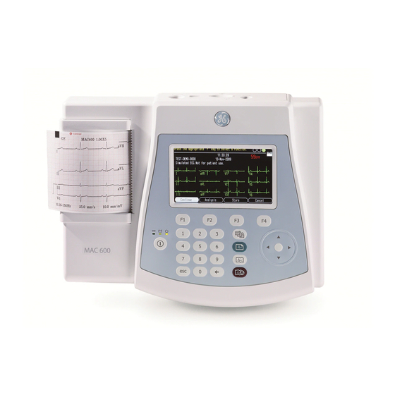
Equipment Overview: General Description General Description The MAC 600 Resting ECG Analysis System is a 10-lead, 12-channel device with an integrated 4.3 inch WQVGA color display and three-inch thermal printer. This is a portable device with a lithium ion battery and smart charger. -
Page 19: Back View
Equipment Overview: General Description Back View Table 2-2. Back view Legend Name Description DC In Socket Input socket for connecting external ACDC adaptor. SD Card slot Slot for using the SD card. Product Label Displays product name, site of manufacture, power specification, and relevant symbols. -
Page 20: Side View
Equipment Overview: General Description Side View Table 2-3. Side View Legend Name Description ECG signal input connector Connector for patient cable Revision G 2047426-002... -
Page 21: Keypad
Equipment Overview: General Description Keypad Table 2-4. Keypad Legend Name Description Power Turns the system on or off. Power LED Indicates the unit is plugged in and receiving DC power. Battery LED Indicates various battery states: Solid amber light indicates that the battery is charging. ... -
Page 22: Bottom View
Equipment Overview: General Description Table 2-4. Keypad Backspace Deletes characters Stop Stops the printing. Bottom View Table 2-5. Bottom View Legend Name Description Battery Compartment Holds the rechargeable Lithium-Ion battery Option Code Label Displays the option code label (Optional) Table 2-6. Option Code Label Contents Option Description Measurement... -
Page 23: General Description
Equipment Overview: General Description Table 2-6. Option Code Label Contents XML Format PDF Format NOTE The option label only includes information regarding ordered options. If no options were ordered, this label is not present. General Description Hardware/Firmware Architecture: The MAC 600 hardware subsystems include the following: CPU board ... - Page 24 Equipment Overview: General Description Display Keypad Thermal printer External ACDC Power supply (of 100V -240V +/- 10% AC and gives single output of 12V @ 1.5 A) Housing Battery Revision G 2047426-002...
-
Page 25: Troubleshooting
Troubleshooting Revision G 2047426-002... - Page 26 For your notes Revision G 2047426-002...
-
Page 27: General Fault Isolation
Troubleshooting: General Fault Isolation General Fault Isolation Power-up Self-Test See Equipment Overview in the MAC 600 Operator’s Manual for information regarding the operation of the device. On power-up, the start-up screen opens. NOTE Battery charging indication and time may vary. If the equipment is not working properly: Is the unit turned on? ... -
Page 28: Visual Inspection
Troubleshooting: General Fault Isolation Visual Inspection A visual inspection of the equipment can detect disconnected cables, debris on circuit boards, missing hardware, and loose components. These could cause symptoms, and equipment failures. NOTE Perform the visual checks before starting any troubleshooting procedures. -
Page 29: Performing Diagnostic Tests
Troubleshooting: General Fault Isolation Table 3-1. Visual Inspection List Sl No: Area Look for: SD card Cracked SD card Broken gold contacts Performing Diagnostic Tests Verify that the MAC 600 Resting ECG Analysis System operates properly by running the diagnostic tests. These tests check the operation of the display screen, buzzer, keypad, thermal writer, battery, and communications. -
Page 30: Testing The System Information
Troubleshooting: General Fault Isolation The following window opens. System Setup 2 5. Press the F1 and Lead keys together. The following window opens prompting you to enter the Service password. System Setup 3 6. Enter service password 7763. 7. Press Enter. The following window opens. -
Page 31: Testing The Display
Troubleshooting: General Fault Isolation 1. From the System Diagnostics menu, select System Information Test. The following window opens. Testing System Information 2. Check if the serial number and ARM software version (Application software) are correct. NOTE Check with manufacturing for the current ARM software (Application software) version. -
Page 32: Testing The Buzzer
Troubleshooting: General Fault Isolation NOTE If the color option is disabled in the device, display will show a white bar in place of the four color bars. 3. Press the right arrow key on the keypad to move the color bars horizontally across the screen. -
Page 33: Testing The Keypad
Troubleshooting: General Fault Isolation Testing the Keypad 1. From the Diagnostics menu, select Keyboard Test. The following window opens. 2. Press each key on the keypad and verify that the response appears in the corresponding representation of that key on the screen. When the corresponding key is pressed, a decimal value appears on the screen. - Page 34 Troubleshooting: General Fault Isolation Table 3-2. : Testing the Keypad Function key F2 Function key F3 Function key F4 Lead key Lead Resting ECG key Rhythm key Stop key Stop Trim Left key Trim Up key Trim Right key Trim Down key Trim Center key Escape key 3.
-
Page 35: Writer Test
Troubleshooting: General Fault Isolation Writer Test 1. From the Diagnostics menu, select Writer Tests. The following window opens. 2. Perform the 50mm/s Speed Test. a. Select the 50mm/s Speed Test button. The writer prints the 50 mm/s speed test report. b. -
Page 36: Battery Tests
Troubleshooting: General Fault Isolation Battery Tests 1. From the Diagnostics menu, select Battery Tests. The following window opens. 2. Select Battery Status. The following window opens. 3. Check the battery voltage from this menu along with charging status. Battery voltage can range from 6.0 – 8.5V. If connected to mains, the system displays Charging battery. -
Page 37: Acq. Module Tests
Troubleshooting: General Fault Isolation 2. To run the test, connect pin 3 to pin 5 using a jumper and then press any key to start. (For the connector pin outs, refer to the following figure). The test will return a pass/fail for several baud rates. Table 3-3. -
Page 38: Sd Card Tests
Troubleshooting: General Fault Isolation SD Card Tests 1. From the Diagnostics menu, select SD Card Tests. The following window opens. 2. The SD Card Tests performs a read/write test on the SD card currently installed. The test will respond with a PASS or FAIL. NOTE If the card is not formatted correctly, an error message will appear at the bottom of the screen. - Page 39 Troubleshooting: General Fault Isolation OLD PWA FRU NEW PWA FRU Connector Description PN: 2047330-001 PN:2066447-002 Patient Cable Battery Revision G 3-15 2047426-002...
-
Page 40: Equipment Problems
Troubleshooting: Equipment Problems Equipment Problems Paper Error Message 3-16 Revision G 2047426-002... -
Page 41: Paper Moving But Not Printing
Troubleshooting: Equipment Problems Paper Moving But Not Printing Revision G 3-17 2047426-002... -
Page 42: Printer Door Open Message
Troubleshooting: Equipment Problems Printer Door Open Message 3-18 Revision G 2047426-002... -
Page 43: Printing Only Baselines
Troubleshooting: Equipment Problems Printing Only Baselines Revision G 3-19 2047426-002... -
Page 44: Battery Error Message
Troubleshooting: Equipment Problems Battery Error Message 3-20 Revision G 2047426-002... -
Page 45: Unit Not Turning On In Battery Mode
Troubleshooting: Equipment Problems Unit Not Turning ON in Battery Mode Revision G 3-21 2047426-002... -
Page 46: External Power Led Not Lighting Up
Troubleshooting: Equipment Problems External Power LED Not Lighting Up 3-22 Revision G 2047426-002... -
Page 47: External Power Led Lights Up But Unit Not Switching On
Troubleshooting: Equipment Problems External Power LED Lights Up But Unit Not Switching ON Revision G 3-23 2047426-002... -
Page 48: Data Does Not Print On Upper And Lower Edges Of Paper
Troubleshooting: Equipment Problems Data Does Not Print on Upper and Lower Edges of Paper 3-24 Revision G 2047426-002... -
Page 49: Blank Or Unstable Display With Color Patches
Troubleshooting: Equipment Problems Blank or Unstable Display With Color Patches Revision G 3-25 2047426-002... - Page 50 Troubleshooting: Equipment Problems 3-26 Revision G 2047426-002...
-
Page 51: Maintenance
Maintenance Revision G 2047426-002... - Page 52 For your notes Revision G 2047426-002...
-
Page 53: Preparing System For Fru Replacement
OPERATOR SAFETY — Repairing the device when powered on may cause injury. Necessary Personal Protective Equipment are recommended while performing maintenance. WARNING To ensure patient safety, use only parts and accessories manufactured or recommended by GE Healthcare. Revision G 2047426-002... -
Page 54: Required Tools And Manuals
Maintenance: Preparing System for FRU Replacement Required Tools and Manuals Table 4-1. Required tools and manuals Description Sl no: Phillips screwdriver Anti-static wrist strap Service manual as needed for reference Safety tester for measurements according to 60601-1 Connecting wires and clips required for electrical safety tests (optionl) Multi-meter Multi Lead ECG simulator... -
Page 55: Replacing The Battery
Maintenance: Preparing System for FRU Replacement Table 4-2. PWA Connectors OLD PWA FRU NEW PWA FRU Connector Description PN: 2047330-001 PN:2066447-002 Patient Cable Battery Replacing the Battery 1. Lift the snap region in the battery cover and slide it out of the bottom cover. -
Page 56: Replacing The Thermal Printer
Maintenance: Preparing System for FRU Replacement Replacing the Thermal Printer Class II version- Earth cable routing: Revision G 2047426-002... - Page 57 Maintenance: Preparing System for FRU Replacement Class I - Earth cable routing: Table 4-3. Replacing the Thermal Printer Legend Description Earthing Cable Fasteners 1. Open the device and printer door as described in “Opening the Device” on page 4-8. 2. Open connector J10 for the old PWA and J5 for the new PWA (refer “PWA Connector Details”...
-
Page 58: Opening The Device
Maintenance: Preparing System for FRU Replacement Opening the Device Table 4-4. Opening the Device Legend Description Detach key sheet FPC from main board Detach display FPC from main board Revision G 2047426-002... - Page 59 Maintenance: Preparing System for FRU Replacement 1. Remove all cables from the unit, if connected. 2. Remove the battery as described in“PWA Connector Details” page 4-4. 3. Turn the device upside down and remove the four fastening screws on the bottom. 4.
- Page 60 Maintenance: Preparing System for FRU Replacement PWA Connectors for FRU PN 2066447-002 (new PWA). PWA Connector Details Table 4-5. PWA Connectors OLD PWA FRU NEW PWA FRU Connector Description PN: 2047330-001 PN:2066447-002 Key sheet Display Printer SD Card Power In RS232 JATAG Modem...
-
Page 61: Reworking The Power Supply (Class Ii To Class I)
Maintenance: Preparing System for FRU Replacement Reworking the Power Supply (Class II to Class I) The MAC600 Class II Power Supply (PS) FRU P/N 2047328-001 is obsolete. The new power supply is qualified as Class I and the P/N is 2047328-002. -
Page 62: Earth Cable Routing
Maintenance: Preparing System for FRU Replacement Earth Cable Routing Verify the earth cable routing is as shown in the following figure. It should connect screw A and screw B. This is the Class II Earth (ground) cable routing. To change the cable routing to comply with Class I requirements, perform the following procedure. -
Page 63: Changing The Product Label
Maintenance: Preparing System for FRU Replacement 5. Verify the new Earth Cable routing is as shown in the following photo. 6. Close the device and do the functional and safety testing for the power supply and Main PCB after the replacement of the FRU. See “Functional Checkout”... - Page 64 Maintenance: Preparing System for FRU Replacement Table 4-8. Product Labels Legend Description Product label Serial number label 1. The existing product label shows the product is class II (the double square box on the following label indicates that the device is Class II).
-
Page 65: Replacing The Display
Maintenance: Preparing System for FRU Replacement Replacing the Display NOTE Sequence of snap detachment (1,2,3,4,5) is same for both displays. Table 4-9. Replacing the Display Legend Description 1, 2, 3, 4, 5 Sequence of snap detachment. Dotted line direction of snap pull. Continuous line direction of display holder pull. - Page 66 Maintenance: Preparing System for FRU Replacement 1. Open the device as described in “Opening the Device” on page 4-8. 2. Raise the top cover of the housing and disconnect the keypad cable from the J4 connector for the old PWA, or J7 connector for the new PWA and display cable from the J5 connector for the old PWA or J6 connector for the new PWA.
-
Page 67: Replacing The Main Pcb Assembly
Maintenance: Preparing System for FRU Replacement Replacing the Main PCB Assembly NOTE If possible, save the current settings before replacing the PCB assembly. For information about saving system setup, see “Saving Setup” on page 4-30. Adding Ferrite to the Power Supply If you are replacing an old PWA with a new PWA, follow these steps to add ferrite to the power supply. -
Page 68: Replacing The Main Pcb
Maintenance: Preparing System for FRU Replacement 6. Press the ferrite to close the lock. 7. Reconnect the cables. 8. Perform functional tests associated with the adapter change. Replacing the main PCB NOTE Before replacing the main PWA we recommend that you update the SW (refer to “Programming MAC 600 Device Without User Interface”... -
Page 69: Replacing The Daughter Pcb Assembly
Maintenance: Preparing System for FRU Replacement 9. Enter the serial number and option code (optional) as described in “Restoring Setup” on page 4-30. 10. Adjust the time and date. See MAC 600 operator’s Manual for setting date and time. 11. If possible, set the configuration to the previous user settings. If not, select the default settings. -
Page 70: Preventive Maintenance
10. Attach the upper section of the device to the lower section with the four screws. Preventive Maintenance The MAC 600 system does not require any periodic calibration. GE Healthcare does not recommend any preventive maintenance for this system. However, the user may perform the following preventive maintenance steps. Recommended Maintenance ... - Page 71 Maintenance: Preparing System for FRU Replacement 1. Use a disposable wrist strap to avoid static electricity. 2. Open the printer door. 3. Wipe the glazed surface of the thermal print head gently with wringed swabs dipped in ethyl alcohol. 4. When the surfaces are dry, close the printer door. NOTE Do not hit the thermal print head with anything hard.
-
Page 72: Functional Checkout
Maintenance: Preparing System for FRU Replacement Functional Checkout The functional checkout procedures apply to all MAC 600 systems. NOTE The FRU checkout procedure for any listed FRU also applies to its internal PCBs and components. FRU replacement procedures are contained within this chapter of the manual. -
Page 73: Check Out Procedure
Maintenance: Check out Procedure Check out Procedure Operational Checks Perform the functional checkout procedures that are applicable to the replacement procedure that was performed. 1. Verify the power-up self-test passed. See “Power-up Self-Test” page 3-3. 2. Verify the serial number restored successfully. See “Serial Number Entry”... -
Page 74: Electrical Safety Tests
Maintenance: Check out Procedure Electrical Safety Tests The suggested safety analysis tests comply to the international standard IEC 60601-1. The tests should be performed with safety testing instruments with measuring circuits calibrated according to IEC 60601- 1. To ensure personal safety, refer to the “testing instrument’s user documentation”. -
Page 75: Earth Leakage (Ac Line) Current Test
Maintenance: Check out Procedure Measuring Circuit [M] and the displayed values are converted to leakage current. Earth Leakage (AC line) Current Test This test measures leakage current of the device. The device has to be turned on and off, and connected to your safety-testing equipment. Measurements should be taken under the following conditions (refer to “Electrical Safety Tests”... -
Page 76: Patient Leakage Current Tests
Maintenance: Check out Procedure N.C. S.F.C 500 uA (IEC) 1,000 uA (IEC & UL) 150 uA (UL) Patient Leakage Current Tests These tests measure leakage current of the device’s floating inputs (patient connections ground). Patient Leakage Current to Ground This test measures leakage current from the floating input (patient connection) to ground during normal condition (N.C.) and single fault condition (S.F.C). -
Page 77: Patient Leakage Current, Mains On Applied Part
Maintenance: Check out Procedure The test has failed if the measured values are greater than: N.C. S.F.C Polarity: NORM & Polarity: NORM & RVS S1 RVS S1 (neutral): closed I S1 (neutral): closed open GND: open I GND: closed Total tests/combinations: 2 Total tests/combinations: 4 10 uA (IEC &... - Page 78 Maintenance: Check out Procedure In all cases, the leakage current is measured from the floating (patient) inputs jack of the device to ground. To setup the leakage current test: 1. Disconnect the safety tester from the line voltage. 2. Ground all signal input/output connections (all SIPs/SOPs connected to ground).
- Page 79 Maintenance: Check out Procedure Verify the current leakage test results meet the requirements. Perform electrical safety checks when indicated. All indicated electrical safety checks require a pass/ fail indication for the steps performed. Record the measurement values in your debrief. 1.
-
Page 80: Saving Setup
Maintenance: Check out Procedure Saving Setup For saving System set up to an SD card, the SD card option need not be enabled. 1. Select Setup. 2. Enter the setup password 1111. 3. Press Enter. 4. Select Save Setup using the arrow and press the Enter key. 5. -
Page 81: Application Software Update
Maintenance: Check out Procedure 5. Enter the service password 7763 6. Press Enter. 7. If the serial number already exists, the system displays the stored serial number on the screen. Press the Enter key again if you wish to change the serial number or press the esc key to exit the serial number entry screen. -
Page 82: Boot Software Update
Maintenance: Check out Procedure for normal operation. 10. To verify the correctness of programming, go to “Testing the System Information” on page 3-6 and check if the displayed ARM Software Version is the latest or not. BOOT Software Update 1. Select Setup. 2. -
Page 83: Programming Mac 600 Device Without User Interface
Maintenance: Check out Procedure the SD card is not formatted, the system will display Format SD Card. You may format it by pressing the Enter key and storing the system log or press the esc key to exit without formatting the SD card. - Page 84 Maintenance: Check out Procedure 6. Select the System password line and type the new password in the space. 7. Press the Enter key. 8. Select Save Setup from the System Setup menu. 9. Select To system. 4-34 Revision G 2047426-002...
-
Page 85: Parts And Replacements
Parts and Replacements Revision G 2047426-002... - Page 86 For your notes Revision G 2047426-002...
-
Page 87: Ordering Parts
You can order parts for the assemblies, stand-alone FRUs, and FRU kits that are considered field-serviceable. Only items, assemblies, and kits, which have part numbers, provided in this chapter are available as FRUs. To order parts, contact GE Healthcare Service or a GE Healthcare approved vendor. Accessory Kits Table 5-1. -
Page 88: Patient Cables
2029894-001 Clamp electrode for limb leads, AHA, set of 4, with labels 2029892-001 Bulb electrode for chest leads, set of 6, with labels 9490-210 CLIP UNIVERSAL GE 10/PKG 9623-003P SILVER MACTRODE PLUS 1000 / CASE 402207-210 BABYMAC ELECTRODE 10L 50CD/CS... -
Page 89: Consumable
Parts and Replacements: Ordering Parts Consumable Table 5-4. Consumable Part Number Description 217 083 18 Electrode cream, 250-ml refill bottle Writer Paper Table 5-5. Writer Paper Part Number Description 2030887-001 Standard thermal recording paper, 80 mm x 90 mm (width), 10 Z fold pads/ case 2030888-001 Standard thermal recording paper, 80 mm x 15.7 m, 10 rolls/case... - Page 90 Parts and Replacements: Ordering Parts Table 5-7. Operator’s Guide 2047426-009 MNL OPR MAC 600 DUT Dutch (DUT) 2047426-010 MNL OPR MAC 600 EST Estonian (EST) 2047426-011 MNL OPR MAC 600 FIN Finnish (FIN) 2047426-012 MNL OPR MAC 600 FRE French (FRE) 2047426-013 MNL OPR MAC 600 GER German (GER)
-
Page 91: Qrg P/Ns
Parts and Replacements: Ordering Parts QRG P/Ns Table 5-8. Operator’s Guide Part Number Description Language 2047426-003 MNL QRG MAC 600 English English (ENG) 2047426-032 MNL QRG MAC 600 BUL Bulgarian (BUL) 2047426-033 MNL QRG MAC 600 CHS Chinese (CHS) 2047426-034 MNL OPR MAC 600 CROA Croatian (CRO) 2047426-035... -
Page 92: Power Cords
Parts and Replacements: Ordering Parts Power Cords Table 5-9. Power Cords Part Number Description Country 405535-006 Power supply cord RA Hospital Grade 13A 125 V 10 FT North America/ Central America 401855-018 Power Cord ST CHINA RA PLUG 10A 250V 2.5M China 401855-101 Power Supply Cord ST CONT EURO 10A 250V 2.5M... -
Page 93: Field Replaceable Units (Frus)
Parts and Replacements: Ordering Parts Table 5-11. MAC 600 Upgrade Options 2047927-012 KIT UPGRADE EXT STOR + SERIAL CBL 2047927-015 KIT UPGRADE PDF FORMAT Field Replaceable Units (FRUs) 2066456-001 FRU - Power Supply Medical Class I (For China Only) Revision G 2047426-002... -
Page 94: 2047328-002 Fru External Power Supply - Class I
Parts and Replacements: Ordering Parts 2047328-002 FRU EXTERNAL POWER SUPPLY - CLASS I Table 5-12. Power Supply FRU Kit ITEM ITEM DESCRIPTION PWR Sply SW 18W SL Power Product Label - Expedition Replacement Instructions for Power Supply FRU for MAC 600 See the instructions for “Reworking the Power Supply (Class II to Class I)”... -
Page 95: Mechanical Fru Kit 1
Parts and Replacements: Ordering Parts Mechanical FRU Kit 1 2047329-001 MECHANICAL FRU KIT 1 Table 5-13. Mechanical FRU Kit 1 ITEM ITEM DESCRIPTION SCR DIN7985-M3X10-4.8-Z-A2F (ISO7045) SCR DIN7985-M2X6-4.8-Z-A2F (ISO7045) SCR FH #4-40X1/4" ZINC AHNL.DIN965 BUMPON SJ-6125, 15.9MM DIA, 6.35MM THK FRU - CKT BD MAC 600 CPU Board Revision G 5-11... -
Page 96: Lcd Fru Kit (Nec)
Parts and Replacements: Ordering Parts 2047330-001 FRU - CKT BD MAC 600 CPU BOARD 2066447-002 FRU - PWA MAC 600 (new) (FRU PWA used in MAC 600 Devices having Product Code SP5) NOTE FRU PN: 2047330-001 is used in MAC 600 devices having Product Code SF7. -
Page 97: Lcd Fru Kit (Koe)
Parts and Replacements: Ordering Parts LCD FRU Kit (KOE) 2100910-001 LCD AND DISPLAY O-RING (NEW) FRU KIT Table 5-15. LCD FRU Kit (KOE) ITEM ITEM DESCRIPTION LCD MODULE - 4.3 INCH DISPLAY O-RING - EXPEDITION NOTE Order FRU PN: 2100910-001 as a replacement, only for product code SPY. -
Page 98: Fru - Lcd Module Holder - Expedition (Nec)
Parts and Replacements: Ordering Parts FRU - LCD Module Holder - Expedition (NEC) 2047332-001 FRU - LCD MODULE HOLDER - EXPEDITION NOTE FRU PN: 2047332-001 is used in MAC 600 devices having Product Codes SF7 and SP5. 5-14 Revision G 2047426-002... -
Page 99: Fru - Lcd Module Holder - Expedition (Koe)
Parts and Replacements: Ordering Parts FRU - LCD Module Holder - Expedition (KOE) 2100912-001 LCD MODULE HOLDER (NEW) - FRU NOTE FRU PN: 2100912-001 is used in MAC 600 devices having Product Codes SPY. Revision G 5-15 2047426-002... -
Page 100: Fru - Cover Battery - Expedition
Parts and Replacements: Ordering Parts FRU - Cover Battery - Expedition 2047333-001 FRU - COVER BATTERY - EXPEDITION Table 5-16. FRU - Cover Battery - Expedition ITEM ITEM DESCRIPTION COVER BATTERY - EXPEDITION BUMPON SJ-6125, 15.9MM DIA, 6.35MM THK 5-16 Revision G 2047426-002... -
Page 101: Fru - Daughter Board For Lcd Module - Expd'n (Nec)
Parts and Replacements: Ordering Parts FRU - Daughter Board for LCD Module - EXPD'N (NEC) 2047334-001 FRU - DAUGHTER BOARD FOR LCD MODULE - EXPD'N (NEC) Table 5-17. FRU - Daughter Board for LCD Module - EXPD’N (NEC) ITEM ITEM DESCRIPTION PCB MAC600 LCD DISPLAY DAUGHTER BOARD FERRITE - (7427212) PAD, FLOPPY MAC SERIES (Adhesive) -
Page 102: Fru - Daughter Board For Lcd Module - Expd'n (Koe)
Parts and Replacements: Ordering Parts FRU - Daughter Board for LCD Module - EXPD'N (KOE) 2100913-001 FRU - DAUGHTER BOARD FOR LCD MODULE - EXPD'N (KOE) Table 5-18. FRU - Daughter Board for LCD Module - EXPD’N (KOE) ITEM ITEM DESCRIPTION PCB MAC600 LCD DISPLAY DAUGHTER BOARD FERRITE - (7427212) PAD, FLOPPY MAC SERIES (Adhesive) -
Page 103: Printer Door Fru Kit
Parts and Replacements: Ordering Parts Printer Door FRU Kit 2047335-001 PRINTER DOOR FRU KIT Table 5-19. Printer Door FRU Kit ITEM ITEM DESCRIPTION PRINTER DOOR - EXPEDITION PRINTER DOOR - HINGE COMPONENT Revision G 5-19 2047426-002... -
Page 104: Cover Top Fru Kit
Table 5-20. Cover Top FRU Kit ITEM ITEM DESCRIPTION COVER TOP - EXPEDITION (with Printing) BACK PANEL - EXPEDITION (with Printing) CORE FERRITE 7427210 PAD, FLOPPY MAC SERIES (Adhesive) NAMEPLATE 15MM GE LOGO MEMBRANE KEY SHEET - EXPEDITION 5-20 Revision G 2047426-002... -
Page 105: Cover Bottom Fru Kit
Parts and Replacements: Ordering Parts Cover Bottom FRU Kit 2047337-001 COVER BOTTOM FRU KIT Table 5-21. Cover Bottom FRU Kit ITEM ITEM DESCRIPTION COVER BOTTOM - EXPEDITION BUMPON SJ-6125, 15.9MM DIA, 6.35MM THK PAPER LIFTING TAPE PRODUCT LABEL EXPEDITION Revision G 5-21 2047426-002... -
Page 106: Mechanical Fru Kit 2
Parts and Replacements: Ordering Parts Mechanical FRU Kit 2 2047338-001 MECHANICAL FRU KIT 2 Table 5-22. Mechanical FRU Kit ITEM ITEM DESCRIPTION PRINTER MOUNTING BASE PATIENT CABLE CONNECTOR HOLDER FRU Printer Module 2047339-001 FRU PRINTER MODULE 5-22 Revision G 2047426-002... -
Page 107: Fru Battery
Parts and Replacements: Ordering Parts FRU Battery 2047357-001 FRU BATTERY FRU Software Update - SD Card 2047358-001 FRU SOFTWARE UPDATE - SD CARD Table 5-23. FRU Software Update - SD Card ITEM ITEM DESCRIPTION CARD SECURE DIGITAL - 2GB LABEL SD CARD FOR MAC600 SW KIT Revision G 5-23 2047426-002... -
Page 108: Fru Cable Kit
Parts and Replacements: Ordering Parts FRU Cable Kit 2047359-001 FRU CABLE KIT Table 5-24. FRU Cable Kit ITEM ITEM DESCRIPTION CABLE FOR EARTHING FERRITE - (7427212) PAD, FLOPPY MAC SERIES (Adhesive) CABLE MAC 600LCD CA 5-24 Revision G 2047426-002... -
Page 109: Fru Serial Cable
Parts and Replacements: Ordering Parts FRU Serial Cable 2047566-001 ASSY SERIAL CABLE - FERRITE Revision G 5-25 2047426-002... - Page 110 Parts and Replacements: Ordering Parts 5-26 Revision G 2047426-002...
-
Page 111: Technical Specification
Technical Specification Revision G 2047426-002... - Page 112 Technical Specification: Instrument Type Microprocessor augmented automatic electrocardiograph; 10-leadwire, 12 lead simultaneous acquisition with programmable lead configuration. Processing ECG Interpretation: Marquette 12SL ECG Analysis Program for Adults and Pediatrics Computerized measurements: 12-lead analysis ECG analysis frequency: 500 samples/second (sps) ECG storage: Optional.
- Page 113 SD card interface Compatible with Cardiosoft V6.51 Storage (optional) ECG Storage Format GE Healthcare storage format for MUSE and Cardiosoft. XML storage format. PDF storage format PDF File name format User configurable file name, which includes patient ID, secondary ID, Date of Birth, ECG recording date and time.
- Page 114 Technical Specification: External adaptor specifications Input voltage: 100 to 240 VAC ±10% Input current: Maximum 0.5A @ 90 VAC - 240 VAC Operating frequency: 50 to 60 Hz ±3Hz Output voltage: 12 ± 5% Battery specifications Battery type: Replaceable and rechargeable, Lithium Ion Battery capacity: 7.2V typical, 2.25 AH ±10% 360 minutes of continuous operation without recording or...
- Page 115 Technical Specification: Certification Class I, type CF defibrillator proof (for China shipments and for device serial number equal to or greater than SF713500001PA) Class II, type CF defibrillator proof (for device serial number less than SF713500001PA excluding China Shipments) UL 60601-1 Medical Electrical Equipment, part 1:General Requirements for Safety CAN/CSA C22.2 No.
- Page 116 Technical Specification: Revision G 2047426-002...
-
Page 117: Electromagnetic Compatibility
Electromagnetic Compatibility Revision G 2047426-002... - Page 118 Electromagnetic Compatibility: Changes or modification to the MAC 600 system not expressly approved by GE Healthcare could cause EMC issues. This system is designed and tested to comply with applicable regulations regarding EMC and needs to be installed and used according to the EMC information stated as follows.
-
Page 119: Guidance And Manufacturer's Declaration-Electromagnetic Emissions
Electromagnetic Compatibility: Guidance and Manufacturer’s Declaration-Electromagnetic Emissions Guidance and Manufacturer’s Declaration- Electromagnetic Emissions Emissions test Compliance Electromagnetic environment-guidance RF emissions Group 1 The MAC 600 uses RF energy for its internal EN 55011 function. Therefore, its RF emissions are very low and are not likely to cause any interference in nearby electronic equipment. -
Page 120: Guidance And Manufacturer's Declaration-Electromagnetic Immunity
Electromagnetic Compatibility: Guidance and Manufacturer’s Declaration-Electromagnetic Immunity Guidance and Manufacturer’s Declaration- Electromagnetic Immunity Immunity test EN60601 test level Compliance level Electromagnetic environment-guidance Electrostatic discharge (ESD) ± 6 kV contact ± 6 kV contact Floors should be wood, concrete or ceramic tile. If IEC 61000-4-2 ±... - Page 121 Electromagnetic Compatibility: Guidance and Manufacturer’s Declaration-Electromagnetic Immunity Immunity test EN60601 test level Compliance level Electromagnetic environment-guidance Portable and mobile RF communications equipment should be used no closer to any part of the MAC 600, including cables, than the recommended separation distance calculated from the equation applicable to the frequency of the transmitter.
-
Page 122: Recommended Separation Distance
Electromagnetic Compatibility: Guidance and Manufacturer’s Declaration-Electromagnetic Immunity Recommended Separation Distance The following table provides the recommended separation distances (in meters) between portable and mobile RF communication equipment and the MAC 600 system. The MAC 600 system is intended for use in the electromagnetic environment on which radiated RF disturbances are controlled. -
Page 123: Index
Index Revision G 2047426-002... - Page 124 Index Manual purpose 2 Accessing the System Diagnostics Function 5 Accessory kits 3 Opening the Device 5 Acq. Module Tests 13 Operational Checks 13 Application Software Update 21 Operator’s guides 5 Ordering Information 6 Back View 4 Ordering Parts 3 Battery error 19 Battery Tests 11 Paper Error problem 15...
- Page 125 Index Testing the Keypad 8 Testing the System Information 6 Top View 3 Unit not turning ON in battery mode 20 Visual Inspection 4 Warnings, cautions, and notes 3 Warranty 6 Writer paper 5 Writer Test 10 Revision G 2047426-002...
- Page 126 Index Revision G 2047426-002...
- Page 127 GE Medical Systems GE Medical Systems Information Technologies GmbH Information Technologies Asia; Information Technologies, Inc. Munzinger Straße 5 GE (China) Co., Ltd. 8200 West Tower Avenue D-79111 Freiburg No.1 Huatuo Road Milwaukee, WI 53223 USA Germany Zhangjiang Hi-tech Park Pudong...
Need help?
Do you have a question about the MAC 600 SPY and is the answer not in the manual?
Questions and answers