
Related Manuals for GE MAC 3500


Summary of Contents for GE MAC 3500
- Page 1 GE Healthcare 3500 Resting ECG Analysis System Version 9D Service Manual 2021337-036 Revision L...
- Page 2 MUSE ,CASE, MAC, MARS, MULTI-LINK, and 12SL are trademarks owned by GE Medical Systems Information Technologies, Inc., a General Electric Company going to market as GE Healthcare. All other trademarks are owned by their respective owners. © 2005-2008, 2010, 2013, 2014, 2019 Revision L MAC™...
-
Page 3: Table Of Contents
Contents Introduction Manual Information ..........1-3 Revision History . - Page 4 Troubleshooting Assembly Descriptions ..........4-3 PCB Block Diagram .
- Page 5 Battery Replacement ......... . . 5-6 Remove MAC 3500 System From Trolley ......5-7 MAC Series Trolley .
- Page 6 Sub-Assemblies ..........6-11 MAC 3500 Display Assembly, pn 2026799-002 ....6-11 MAC 3500 KISS Pump Assembly, pn 2022882-002 .
- Page 7 Hardware Kit for MAC 3500, pn 2030869-001 ....6-24 MAC 3500 Plastics Kit, pn 2030898-001 ....6-25 MAC 3500 Top Cover Kit, pn 2030899-001 .
- Page 8 Circuit Board Compatibility Matrix ........B-4 Supported Software Update Paths .
-
Page 9: Introduction
Introduction Revision L MAC™ 3500 Resting ECG Analysis System 1-1 2021337-036... - Page 10 For your notes Revision L MAC™ 3500 Resting ECG Analysis System 2021337-036...
-
Page 11: Manual Information
10 October 2008 Added -007 board, 009C SD Card and -002 Comm PC board. Included Functional Checkout Procedure. 08 January 2010 Added PN 2022328-002 PCB MAC 3500 CAMV2. 10 May 2010 Revised security on electronic file. 12 December 2010 Revised to add service disclaimer addendum. -
Page 12: Related Documentation
Introduction: Warnings, Cautions, and Notes Related Documentation The following documents are referenced in this manual and provide additional information that may be helpful in the installation, configuration, maintenance, and use of this product. Part Number Title 2021337-035 MAC™ 3500 Resting ECG Analysis System Operator Manual 2036070-006 Marquette™... -
Page 13: Safety Messages
U.S. Federal law restricts this device to the sale by or on the order of a physician. Responsibility of the Manufacturer GE Medical Systems Information Technologies is responsible for the effects of safety, reliability, and performance only if: Assembly operations, extensions, readjustments, modifications, or repairs ... -
Page 14: General
To ensure patient safety, use only parts and accessories manufactured or recommended by GE Healthcare. Contact GE Healthcare for information before connecting any devices to this equipment that are not recommended in this manual. If the installation of this equipment, in the USA, will use 240 V rather than 120 V, the source must be a center-tapped, 240 V, single-phase circuit. -
Page 15: Equipment Symbols
Introduction: Equipment Symbols Equipment Symbols The following symbols may appear on the product or its packaging. Type BF equipment. The acquisition module is protected from defibrillation shocks. Alternating current. Equipotential. Charge the battery. The flashing amber LED next to this symbol indicates you must connect the system to AC power to re-charge the battery. - Page 16 Introduction: Equipment Symbols This product consists of devices that may contain mercury, which must be recycled or disposed of in accordance with local, state, or country laws. (Within this system, the backlight lamps in the monitor display contain mercury.) Manufacturer name and address. Consult instructions for use.
-
Page 17: Service Information
Refer equipment servicing to GE authorized service personnel only. Any unauthorized attempt to repair equipment under warranty voids that warranty. It is the user’s responsibility to report the need for service to GE or to one of their authorized agents. -
Page 18: Serial Number Format
(and so on) Fiscal week manufactured Production sequence number Manufacturing site Miscellaneous characteristic 1. The product code for the MAC 3500 described in this manual is SCA. Label Format Table 3. Equipment Identification Label Date of manufacture in YYYY-MM format... -
Page 19: Equipment Overview
Equipment Overview Revision L MAC™ 3500 Resting ECG Analysis System 2-1 2021337-036... - Page 20 For your notes Revision L MAC™ 3500 Resting ECG Analysis System 2021337-036...
-
Page 21: General Description
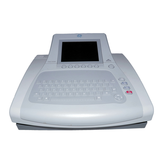
Equipment Overview: General Description General Description The MAC™ 3500 Resting ECG Analysis System is a 12-lead, 12-channel system with a 6.5 inch (165 mm) diagonal display, active patient cable, and battery operation. There are also options for communication capabilities. Side View 104A Name Description... -
Page 22: Back View
Equipment Overview: General Description Back View 105A Name Description back panel connectors Connect peripheral devices here. Secure Digital card slot Insert Secure Digital card for external storage here. ground lug Connect non-grounded peripheral devices to ensure equipotential. main AC power Insert the main AC power cable. -
Page 23: Connector Identification
EXT.VID. Connect an external video display. Point at a MAC 5000, MAC 5500, MAC 3500, or MUSE system’s IR transceiver to transmit or receive ECG data. card slot Insert the system card into this slot to archive or restore data from external media or to update software. - Page 24 Equipment Overview: Connector Identification Table 4. Back Panel Connectors (Continued) ground lug Connect non-grounded peripheral devices to ensure equipotential. main AC power Insert the main AC power cable. Revision L MAC™ 3500 Resting ECG Analysis System 2021337-036...
-
Page 25: Installation
Installation Revision L MAC™ 3500 Resting ECG Analysis System 3-1 2021337-036... - Page 26 For your notes Revision L MAC™ 3500 Resting ECG Analysis System 2021337-036...
-
Page 27: Introduction
Installation: Introduction Introduction This chapter describes how to assemble the MAC 5500 system and optional accessories on the optional MAC Series Trolley, and it identifies the requirements and configurations for using select devices with the ST option. Revision L MAC™ 3500 Resting ECG Analysis System 3-3... -
Page 28: General Assembly
Installation: General Assembly General Assembly The following sections describes these tasks: Adjusting the trolley height Attaching the MAC device to the MAC Series trolley Attaching the optional external modem Attaching the magnetic card reader Attaching the bar code reader ... - Page 29 Swivel Locking Casters Casters 105A NOTE Because the optional trolley is made by another vendor for GE, the serial number format is different from that shown in “Serial Number Format” page 1-10. Revision L MAC™ 3500 Resting ECG Analysis System 3-5...
-
Page 30: Trolley Height Adjustment
Installation: General Assembly Trolley Height Adjustment The optional MAC 3500 Trolley can be assembled for one of two heights, 92.07 cm (36.25 inches) or 84.45 cm (33.25 inches). The trolley is normally shipped at the 92.07 cm (36.25 inches) height but can be changed to fit your needs. To change to... - Page 31 Installation: General Assembly CAUTION Do not over tighten. Over tightening the bolts may cause them to strip. 109A 110A Revision L MAC™ 3500 Resting ECG Analysis System 3-7 2021337-036...
-
Page 32: Installing The Mac™ 3500 Resting Ecg Analysis System
Installation: General Assembly Installing the MAC™ 3500 Resting ECG Analysis System To secure the MAC 3500 to the trolley assembly, follow these steps: Lock the wheels to prevent the trolley from rolling. 111A Remove the end panel by pulling out and up. - Page 33 Installation: General Assembly Secure the MAC 3500 to the trolley by tightening the three captive screws located under the trolley tray. MAC 3500 Replace the end panel by pushing up and in until you hear a snap. 113A Unlock the wheels to allow free movement of the trolley.
-
Page 34: Installing The Optional External Modem Kit
Installing the Optional External Modem Kit NOTE The internal modem is standard for the MAC 3500. The modem and its mounting bracket comes assembled and ready to install on the trolley. To install a modem kit on the trolley, complete the following steps: Find the modem mounting site located under the patient cable arm at the rear of the trolley where the kit is to be installed. - Page 35 Installation: General Assembly Plug the modem cable into connector port 2 on the MAC 3500. Refer to the operator’s manual for information on using the modem. Revision L MAC™ 3500 Resting ECG Analysis System 3-11 2021337-036...
-
Page 36: Magnetic Card Reader Installation
Installation: General Assembly Magnetic Card Reader Installation The magnetic card reader and its mounting bracket are assembled and ready to install on the trolley. Parts are included for two different trolley styles. Disregard and do not use the parts indicated in the following illustration. Do Not Use These Parts on new style trolley... - Page 37 At the front, hold the cable to the side so it clears the front panel as you replace the panel. Plug the cable connector into port A then replace the back panel. Refer to the MAC 3500 Operator’s Manual for information on using the Magnetic Card Reader. Revision L MAC™...
-
Page 38: Barcode Reader Installation
Installation: General Assembly Barcode Reader Installation The barcode reader and its mounting bracket are ready to install on the trolley. To install the Bar Code Reader and its cable mounting bracket on the trolley, complete the following steps: Barcode Reader Cable Clamp Cable... - Page 39 Port A Internal Access Button Next fasten the cable and clamp to the clamp bracket, then close the MAC 3500. Observe that there is enough slack to allow free movement of the cable when re- opening the MAC 3500. Not enough cable slack.
- Page 40 Installation: General Assembly For your notes Revision L 3-16 MAC™ 3500 Resting ECG Analysis System 2021337-036...
-
Page 41: Troubleshooting
Troubleshooting Revision L MAC™ 3500 Resting ECG Analysis System 4-1 2021337-036... - Page 42 For your notes Revision L MAC™ 3500 Resting ECG Analysis System 2021337-036...
-
Page 43: Assembly Descriptions
Troubleshooting: Assembly Descriptions Assembly Descriptions The troubleshooting information in this chapter helps you narrow service problems to one of the replaceable assemblies. These assemblies, illustrated in the following diagrams, are discussed in more detail in the remainder of the chapter along with replacement procedures. - Page 44 Troubleshooting: Assembly Descriptions Revision L MAC™ 3500 Resting ECG Analysis System 2021337-036...
-
Page 45: Connection Diagrams
Troubleshooting: Assembly Descriptions Connection Diagrams The following diagram illustrates the physical I/O connections between the PCB and external devices. The following diagrams provide a detailed look at the connection between the PCB and the LVDS/LED display assembly. Revision L MAC™ 3500 Resting ECG Analysis System 4-5... -
Page 46: Led/Lvds Display Assembly Diagram
Troubleshooting: Assembly Descriptions LED/LVDS Display Assembly Diagram The following illustration diagrams the connections for the LVDS/LED display assembly (2026799-002), and the table that follows it identifies those connections. Item GE Part Number Desciption 2024701-001 ASSY DISPLAY CABLE MAC3500 (CMOS) 2062075-001... -
Page 47: General Fault Isolation
Troubleshooting: General Fault Isolation General Fault Isolation Power-up Self-test See the MAC 3500 Operator’s Manual, Chapter 2, “Equipment Overview: Getting Started” to verify operation. On power-up, the system automatically runs an internal self-test. If all circuits test good, the start up screen displays. If the equipment is not working properly, ask yourself the following questions. -
Page 48: Power-Up Flow Chart
Troubleshooting: General Fault Isolation Power-up Flow Chart Revision L MAC™ 3500 Resting ECG Analysis System 2021337-036... -
Page 49: Poor Quality Ecgs
Troubleshooting: General Fault Isolation Poor Quality ECGs Poor quality ECGs can be caused by factors in the environment, inadequate patient preparation, hardware failures related to the acquisition module, leadwires, cables, or problems in the unit. Use a simulator to obtain an ECG report. If the report is good, the problem is external to the unit. -
Page 50: Visual Inspection
Troubleshooting: General Fault Isolation Visual Inspection A thorough visual inspection of the equipment can save time. Small things— disconnected cables, foreign debris on circuit boards, missing hardware, loose components—can frequently cause symptoms and equipment failures that may appear to be unrelated and difficult to track. NOTE Take the time to make all the recommended visual checks before starting any detailed troubleshooting procedures. -
Page 51: Diagnostic Tests
F5). Type prod at the service password prompt. The System Diagnostics menu appears. NOTE The Floppy Drive Tests option does not apply to the MAC 3500 system. For information on Display Test, go to “Display Test” on page 4-12. ... -
Page 52: Display Test
Troubleshooting: Diagnostic Tests For information on Speaker Test, go to “Speaker Test” on page 4-13. For information on Keyboard Tests, go to “Keyboard Test” on page 4-13. For information on Writer Tests, go to “Writer Test” on page 4-14. ... -
Page 53: Speaker Test
NOTE below. NOTE Pressing the Leads key on the MAC 3500 keyboard will display the word Copy if the key is functioning properly. To verify if all keys are functioning properly, press each key and verify that its ... -
Page 54: Trim Pad Control Test
Troubleshooting: Diagnostic Tests Trim Pad Control Test Trim Pad Control Use the following steps to verify operation of the trim pad control. Press the center of the trim pad control and verify that the word IN is displayed on the screen. Press arrow keys to change the displayed arrow position. - Page 55 Troubleshooting: Diagnostic Tests 50 mm/s Test Pattern I, 25 mm/s Test Pattern I, and 5 mm/s Test Pattern I. Test patterns are used to check the paper speed control. Run each test pattern and check for the following: The length of the printout from start to finish measures 250 mm ± 5 mm. ...
-
Page 56: Battery Test
Troubleshooting: Diagnostic Tests Battery Test Battery tests check the current battery status, battery discharge rate and battery charge rate. Test results are stored in memory and can be printed out. The graphic displayed shows the Battery Test menu. Each test is covered in detail below. Battery Status. - Page 57 To view test results: Connect MAC 3500 to AC power; return to the Battery Test menu and select Print Battery Discharge Test. Test results remain in memory until the Battery Discharge Test is run again. Battery Discharge Test window...
-
Page 58: Communication Test
Troubleshooting: Diagnostic Tests Communication Test Communication tests are available for the COM ports, external modem, internal modem and Ethernet. The Communication Test menu is shown below: COM Port Loopback Test. The Communications (COM) Port Loopback test sends various ASCII characters out from the COM Port’s transmit lines and expects the same character to return to its receiving lines. - Page 59 Troubleshooting: Diagnostic Tests Com Port Loopback Test Results Window NOTE To repair a defective COM port, replace the CPU board. (See “Main CPU Board Replacement” on page 5-22.) External Modem Test. Connect a modem to the COM 2 port and select the ...
- Page 60 Troubleshooting: Diagnostic Tests Internal Modem Test. Select the Internal Modem Test. The test returns the modem ID number, firmware rev, and current parameter settings. If communication with the modem is unsuccessful, the ID and firmware rev display N/A. NOTE If the test fails, consider replacing the communication board.
-
Page 61: Acq. Module Tests
Displays the acquisition board noise floor Tests if the acquisition Displays the software board is communicating. version of the acquisition board NOTE The Button Pressed test does not apply to the MAC 3500 system. Revision L MAC™ 3500 Resting ECG Analysis System 4-21 2021337-036... -
Page 62: Analog I/O Tests
Troubleshooting: Diagnostic Tests Analog I/O Tests The Analog I/O Tests option checks the ANA/TTL connection and consists of four different tests. Analog Output Test. The Analog Output Test. This test involves monitoring of analog outputs using an oscilloscope. Follow the on-screen prompts to run the Analog Output Test. Analog Input Test. - Page 63 Troubleshooting: Diagnostic Tests DCOut Loopback Test. This involves connecting the DC Outputs to the DC Inputs. The test sends all possible values out the DC Outputs and confirms that correct values are read from the DC Inputs. A pass/fail result is displayed at the end of the test.
-
Page 64: Floppy Drive Tests
If test fails you may need to replace the CPU board. (See “Main CPU Board Replacement” on page 5-22.) Floppy Drive Tests This option does not apply to the MAC 3500 system. Revision L 4-24 MAC™ 3500 Resting ECG Analysis System 2021337-036... -
Page 65: Internal Memory Tests
To format a card, insert the SD card and copy data to the card using the Copy All command from File Manager. The MAC 3500 software will then prompt you to format the card. Follow on-screen prompts. Refer to the MAC 3500 Operator’s Manual for details. -
Page 66: Substitute Master Password
Troubleshooting: Diagnostic Tests Substitute Master Password If you do not have access to the system’s password, you can create a master password as follows. At the prompt for the system password, enter meimac. A random 6-digit number displays on the screen. (For example, 876743.) Write the number down and create a new 6-digit number by adding alternating digits from the random number as follows. -
Page 67: Equipment Problems
Troubleshooting: Equipment Problems Equipment Problems ECG Data Noise If the acquired ECG data displays unacceptable noise levels: When troubleshooting noise or signal quality, be sure the problem is not being caused by poor skin preparation, or placement and condition of electrodes. Careful skin preparation is the key to an interference-free ECG. -
Page 68: System Errors
The following errors may occur while you are operating this system. You may be required to perform some action. If you perform the recommended actions and the condition still remains, contact authorized service personnel. See “How to Reach Us” to find out how to contact GE. Problem Cause... -
Page 69: Frequently Asked Questions
Store. Format an SD Card Q: How do I format an SD card in the MAC 3500? A: Most secure digital cards do not require formatting. In the event an unformatted SD card is used with the system, the following message will display: This SD Card cannot be read and requires formatting. -
Page 70: Battery Capacity
Battery Capacity Q: What is the capacity of the battery? A: We recommend that the MAC 3500 be plugged into a wall outlet whenever it is not in use. However, the life of the battery is approximately 100 ECGs and one- page reports or six hours of continuous operation (without printing). -
Page 71: Passwords
If you want the MAC 3500 or 12SL interpretation included on the ECG, put the number of copies you want in the “with” column. If you do not want the MAC 3500 interpretation to print on the ECG, put the number of copies you want in the “without” column. -
Page 72: Entering Patient Data
Q: Why do I lose the Referring MD and Technician names off of my reports when I transmit records to the MUSE system? A: Your MAC 3500 may be transmitting to the SDLC modem on the MUSE system instead of the CSI modem. Check in System Setup to make sure you are transmitting to the MUSE system CSI phone number. -
Page 73: Input And Output Connectors
Troubleshooting: Input and Output Connectors Input and Output Connectors The following pages detail the input/output signals for those connectors. The pin-by- pin descriptions identify the signal names and pin outs for each connector on the unit. A Pins (J1) Table 2. A Pins (J1) Name Data Ground... -
Page 74: Com2 Pins (J5)
Troubleshooting: Input and Output Connectors COM2 Pins (J5) Table 4. COM2 Pins (J5) Name Ground +12V Analog Pins (J6) Table 5. Acquisition Module Connector (J6) Name +12V DC Output 1 TTL Trigger Output Ground Ground DC Output 2 DC Input 1 ECG Output DC Input 2 Revision L ... -
Page 75: Ext. Vid. Pins (J7)
Troubleshooting: Input and Output Connectors EXT. VID. Pins (J7) Table 6. External VGA Video (J7) Name Red Video Green Video Blue Video Ground Ground Ground Ground Ground Ground Ground Horizontal Sync Vertical Sync Revision L MAC™ 3500 Resting ECG Analysis System 4-35... -
Page 76: Cpu Pcb Input/Output Signals
Troubleshooting: CPU PCB Input/Output Signals CPU PCB Input/Output Signals Battery Pack/Monitor, J2 Pin No. Signal 18V Battery Power 18V Battery Power Battery Temperature Sense 3V Temperature Sense Power Battery Ground Battery Ground LCD Backlight, J4 Pin No. Signal 12V Power 12V Power 12V Power Ground... -
Page 77: Lcd, J10
Troubleshooting: CPU PCB Input/Output Signals Keyboard, J8 (Continued) Sense3 Sense5 Sense6 Sense7 Drive0 Drive1 Drive2 Drive3 Drive4 Ground Power Key Drive5 Drive6 Drive7 Drive8 Drive9 Drive10 LCD, J10 Pin No. Signal Ground Pixel Clock Hsync Vsync Ground R0 (LSB) R5 (MSB) Ground G0 (LSB) Revision L... -
Page 78: Power Supply/Motor, J11
Troubleshooting: CPU PCB Input/Output Signals LCD, J10 (Continued) G5 (MSB) Ground B0 (LSB) B5 (MSB) Ground Data Enable 3V Power 3V Power Power Supply/Motor, J11 Pin No. Signal Motor Encoder B 5V Power Motor A Motor Encoder A Ground Motor B 28V Power Ground Battery Charge LED... -
Page 79: Thermal Printer, J12
Troubleshooting: CPU PCB Input/Output Signals Thermal Printer, J12 Pin No. Signal Thermal Printer Power Thermal Printer Power Thermal Printer Power Thermal Printer Power Thermal Printer Power Thermal Printer Power Thermal Printer Power Ground Ground Ground Ground Ground Ground Ground Cue Sense 5V Main Power Ground Data Strobe... -
Page 80: Floppy Disk Drive, J13
Troubleshooting: CPU PCB Input/Output Signals Floppy Disk Drive, J13 (for floppy drive — not installed Pin No. Signal 5V Power Index 5V Power Drive Select 0 5V Power Disk Change Media Sense 0 Media Sense 1 Motor Select 0 Direction Step Ground Write Data... -
Page 81: Acquisition Module, J14
Troubleshooting: CPU PCB Input/Output Signals Acquisition Module, J14 Pin No. Signal Power Ground TX+ (RS485) TX- (RS485) RX+ (RS485) RX- (RS485) KISS Pump, J19 Pin No. Signal KISS Pump Power (12V DC) Acquisition Module, J20 Pin No. Signal TX- (RS485) TX+ (RS485) RX- (RS485) RX+ (RS485) -
Page 82: Lcd Backlight, J23
Troubleshooting: CPU PCB Input/Output Signals LCD Backlight, J23 Pin No. Signal Power 5V DC Power 5V DC Relay Port 1 (Resistance) Relay Port 2 (Resistance) Revision L 4-42 MAC™ 3500 Resting ECG Analysis System 2021337-036... -
Page 83: Maintenance
Maintenance Revision L MAC™ 3500 Resting ECG Analysis System 5-1 2021337-036... - Page 84 For your notes Revision L MAC™ 3500 Resting ECG Analysis System 2021337-036...
-
Page 85: Introduction
Maintenance: Introduction Introduction Recommended Maintenance Regular maintenance, irrespective of usage, is essential to ensure that the equipment will always be functional when required. WARNING Failure on the part of all responsible individuals, hospitals or institutions, employing the use of this device, to implement the recommended maintenance schedule may cause equipment failure and possible health hazards. -
Page 86: Inspection And Cleaning
Maintenance: Inspection and Cleaning Inspection and Cleaning Visual Inspection Perform a visual inspection of all equipment and peripheral devices daily. Turn off the unit and remove power before making an inspection or cleaning the unit. Check the case and display screen for cracks or other damage. ... -
Page 87: Checking Electrical Safety
Maintenance: Checking Electrical Safety Thermal Printhead Checking Electrical Safety The device should be checked annually for current leakage and ground continuity. For details, see “Electrical Safety Checks” on page 5-38. Revision L MAC™ 3500 Resting ECG Analysis System 5-5 2021337-036... -
Page 88: Fru Replacement Procedures
Remove the battery as described in “Battery Replacement”. If the MAC 3500 system is mounted to the trolley, remove it from the trolley as described in “Remove MAC 3500 System From Trolley”. Remove the writer paper. -
Page 89: Remove Mac 3500 System From Trolley
The method for removing the device depends on the type of trolley. MAC Series Trolley Lock the wheels, remove the rear trolley panel then loosen the three captive screws located under the trolley. Pull the MAC 3500 up toward you. Revision L MAC™ 3500 Resting ECG Analysis System 5-7 2021337-036... -
Page 90: Type-S Trolley
Lift the unit from the trolley. NOTE Once the maintenance procedures are complete, reverse these steps to re- assemble the MAC 3500 system to the trolley. Type-S Trolley To dismount the MAC 5500 from the Type-S trolley, follow the steps shown in the following illustration. -
Page 91: Modular Mac Trolley
Maintenance: FRU Replacement Procedures Modular MAC Trolley To remove the device from the modular MAC trolley, perform the following steps. Remove the bolts connecting the mounting tray to the trolley top. Tilt the rear of the device and mounting tray to a 30° angle. Slide the device and mounting tray toward the back of the trolley to remove them. -
Page 92: Power Supply Replacement
Maintenance: Power Supply Replacement Power Supply Replacement Turn the unit over so the bottom side is up. Using a #10 Torx driver, remove the three fasteners holding the power supply in place. 3 fasteners Lift the power supply to expose the wiring harness and ground wire. Remove P2 from J2 on the power supply assembly and the ground wire connection from the power supply chassis. - Page 93 Maintenance: Power Supply Replacement Reassemble the power supply reversing the steps for removal. Before replacing the screws, ensure that the ground wire is routed through the notch in the plastic and not pinched. Revision L MAC™ 3500 Resting ECG Analysis System 5-11...
-
Page 94: Keypad Replacement
Maintenance: Keypad Replacement Keypad Replacement Remove the three fasteners from under the top cover at the front of the unit. 3 fasteners Remove the two fasteners that secure the display panel cover at the back of the unit and then remove the display cover. Remove the two fasteners holding the top of the keypad. - Page 95 Maintenance: Keypad Replacement NOTE The eight plastic standoffs should remain with the keyboard. However, if any do remain in the top cover, use a small pliers to extract from the top cover. Do not damage the rubber cover which is permanently affixed to the top cover.
-
Page 96: Keyboard/Top Cover Assembly Removal & Reassembly
Maintenance: Keyboard/Top Cover Assembly Removal & Reassembly Keyboard/Top Cover Assembly Removal & Reassembly Removal of Keyboard/Top Cover Assembly NOTE Removal of the keyboard/top cover assembly is required in order to replace the following: Printhead assembly (Refer to “Printhead Assembly Replacement” on page ... - Page 97 Maintenance: Keyboard/Top Cover Assembly Removal & Reassembly Five Torx fasteners Remove the two fasteners that secure the display panel cover at the back of the unit and then remove the display cover. Remove the two fasteners holding the two ground wires on either side of the display.
-
Page 98: Replacing The Lvds Converter Board
Maintenance: Keyboard/Top Cover Assembly Removal & Reassembly plastic locking bar NOTE Do not force the cable from its connector. Raise both ends of the plastic locking bar and gently pull the ribbon cable from the connector. 12. Lift upper cover from the assembly. NOTE The back bezel covering the rear connections will fall off as you lift the off the cover. -
Page 99: Keyboard/Top Cover Assembly Reassembly
Maintenance: Keyboard/Top Cover Assembly Removal & Reassembly Remove the screws fastening the LVDS converter board to the display assembly. NOTE Dispose of the old LVDS converter board in compliance with all applicable local and federal laws. Attach the new LVDS converter board to the display assembly using the two screws removed in step 3. -
Page 100: Printhead Assembly Replacement
Maintenance: Printhead Assembly Replacement Printhead Assembly Replacement Remove the battery as described in “Battery Replacement” on page 5-6. Remove the top cover as described in “Keyboard/Top Cover Assembly Removal & Reassembly”. Disconnect the ribbon cable from the connector on the printhead. Close the top of the unit until it snaps into place. -
Page 101: Acquisition Board Replacement
Maintenance: Acquisition Board Replacement Acquisition Board Replacement Remove the battery as described in “Battery Replacement” on page 5-6. Remove the top cover as described in “Keyboard/Top Cover Assembly Removal & Reassembly”. Remove the two Phillips head screws holding the acquisition connector bracket to the acquisition board. -
Page 102: Display Assembly Replacement Procedures
Maintenance: Display Assembly Replacement Procedures Display Assembly Replacement Procedures Remove the battery as described in “Battery Replacement” on page 5-6. Remove the two fasteners that secure the display panel cover at the back of the unit and then remove the display cover. Remove the two fasteners holding the two ground wires on either side of the display. -
Page 103: Kiss Pump Replacement Procedures
Maintenance: KISS Pump Replacement Procedures KISS Pump Replacement Procedures NOTE The KISS pump is an optional accessory. Remove the battery as described in “Battery Replacement”. Remove the two fasteners at the back of the unit that secure the display panel cover in place. -
Page 104: Main Cpu Board Replacement
Maintenance: Main CPU Board Replacement Main CPU Board Replacement Removal of CPU Board NOTE Before you begin, save the current System Setups to an SD card and print System Setup report. This will be used to restore the system setups after replacement of the CPU board. -
Page 105: Reassembly Of Cpu Board
Maintenance: Main CPU Board Replacement Reassembly of CPU Board Insert the new CPU board in place and mount using the fasteners set aside during disassembly. NOTE When replacing the fasteners which hold the two grounding straps in place, be sure to route the grounding straps as shown below. grounding strap grounding... -
Page 106: Software, System Setups, And Option Activation
Maintenance: Main CPU Board Replacement Software, System Setups, and Option Activation Installing the Software After replacing the CPU, you need to install or update the software on the board. Two methods exist for installing software. The standrd method uses prompts displayed on the user interface to indicate installation status. - Page 107 Maintenance: Main CPU Board Replacement If the boot code on the device and the boot code on the SD card are the same version, the following meesages are displayed: Programming Over System will shut down Press any key to continue… Press any key to shut down the device.
- Page 108 Maintenance: Main CPU Board Replacement the device. If the primary boot code cannot detect a valid code within 2 minutes and 6 seconds, the device shuts down. Because the device’s display is not available when the software application cannot be found, the onboard LEDs, DS1 (Red) and DS2 (Green), flash status codes to indicate progress.
-
Page 109: Service Only Setups
Maintenance: Main CPU Board Replacement DS1 (Red) DS2 (Green) Status Error — Could not program all the image files as well as the status page 'Z0'. Flashing Error — Could not program all the image files but the status page 'Z0' updated successfully. When the installation completes successfully, both LEDs will begin to flash. -
Page 110: Restore System Setups
Maintenance: Main CPU Board Replacement Select the appropriate language in the Keyboard menu. 10. Select Return. Restore System Setups Power up the cart. From the Main Menu, select System Setup. Enter the System Password and press Enter. Select Restore Setup from the System Setup menu. Select From SD Card from the Restore Setup menu. -
Page 111: Disable Options
Maintenance: Main CPU Board Replacement Disable Options It is possible to disable an option. In the rare instance you may need this functionality, follow these steps: From the Main Menu, select System Setup > Basic System > Option Activation. In the Option Code field, type x followed by the option’s existing activation code. -
Page 112: Comm Board Replacement
Maintenance: COMM Board Replacement COMM Board Replacement Remove the battery as described in “Battery Replacement” on page 5-6. Using a #10 Torx driver, remove the fasteners from the panel surrounding the LAN and modem ports. 100A Grasp the side edges of the COMM board. Rock the board side to side in the slot as you pull it out along its rails. -
Page 113: Setting Up Lan Communications
Maintenance: COMM Board Replacement Replace the panel surrounding the LAN and modem ports. Setting up LAN Communications Use the following procedure to set up the system's LAN communications after switching the COMM board. For more information, refer to the LAN Option for MAC™... - Page 114 Maintenance: COMM Board Replacement 10. Select Return and press Enter. The Transmission window closes. 11. On the Basic System menu, select Return and press Enter. The Basic System menu closes. 12. On the System Setup menu, select Save Setup >To System. This saves the settings to the communication board and displays the following message: Please wait.
-
Page 115: Writer Roller/Carriage Assembly Replacement
Maintenance: Writer Roller/Carriage Assembly Replacement Writer Roller/Carriage Assembly Replacement Remove the battery as described in “Battery Replacement” on page 5-6. Remove the power supply assembly as described in “Power Supply Replacement” on page 5-10. Inside the power supply compartment, disconnect the cable that connects to the writer assembly to the power supply. -
Page 116: Leakage Tests
Maintenance: Writer Roller/Carriage Assembly Replacement Leakage Tests The leakage tests are safety tests to ensure that the equipment poses no electrical health hazards. Use the table below to determine which tests apply to the unit under test and the maximum allowable leakage currents. For international leakage limits, refer to the internal standards agencies of that particular country. -
Page 117: Functional Checkout Procedures
Maintenance: Functional Checkout Procedures Functional Checkout Procedures This checkout procedure applies to all MAC 3500 systems. NOTE The FRU checkout procedure for any listed FRU also applies to its internal PCBs and components. Perform the applicable product or product configuration dependant procedures when an asterisk * is listed. -
Page 118: Tools
Maintenance: Functional Checkout Procedures Table 4. Option Repairs (Continued) FRU / Option Tools Visual Inspection Checkout Procedure(s) Mag Card Reader 1,2,5 1,3,9 Treadmill or Ergometer I/F Cable 1,2,5 1,3,6 Blood Pressure Monitor 1,2,5 Table 5. Non-FRU Repairs Description Tools Visual Inspection Checkout Procedure(s) No Parts Replaced 1,2,3,4,5,6,7... -
Page 119: Checkout Procedures
Maintenance: Functional Checkout Procedures Fasteners replaced and secured? 10. All harnesses’ and internal wiring has been secured? Checkout Procedures Perform the applicable checkout procedure. Operational Checks Power-up self-test passed? Simulated recorded rhythm strip successful? Simulated recorded ECG successful? Simulated ECG stored on media successful? Simulated ECG data transmitted successfully to MUSE? Exercise device successfully communicates with MAC5500/5000? Blood pressure monitor successfully communicates with MAC5500/5000? -
Page 120: Electrical Safety Checks
Maintenance: Functional Checkout Procedures Electrical Safety Checks 20. Current leakage and ground continuity test results meet requirements? Perform electrical safety checks when indicated. All indicated electrical safety checks require a pass/fail indication for steps performed. Record the measurement values in your debrief. Table 6. - Page 121 Maintenance: Functional Checkout Procedures Table 6. Electrical Safety Checks Leakage Step Result Condition UUT - ON Current Limits Ground Continuity Resistance AC mains power cord ground prong to exposed metal Less than ______ Pass/Fail surface (ground lug) 200m 1.
- Page 122 Maintenance: Functional Checkout Procedures Revision L 5-40 MAC™ 3500 Resting ECG Analysis System 2021337-036...
-
Page 123: Parts Lists
Parts Lists Revision L MAC™ 3500 Resting ECG Analysis System 6-1 2021337-036... - Page 124 For your notes Revision L MAC™ 3500 Resting ECG Analysis System 2021337-036...
-
Page 125: Ordering Parts
The FRU parts lists in this chapter supply enough detail for you to order parts for the assemblies, stand-alone FRUs, and FRU kits considered field serviceable. Only items, assemblies, and kits which have part numbers given in this chapter are available as FRUs. To order parts, contact your GE Healthcare service representative. Revision L MAC™... -
Page 126: Field Replaceable Units (Frus)
Parts Lists: Field Replaceable Units (FRUs) Field Replaceable Units (FRUs) Upper Level Assembly Drawings See Detail B Detail B See Detail A 16 11 11 16 Detail A 66A, 68A, 69A, 70A, 71A Revision L MAC™ 3500 Resting ECG Analysis System 2021337-036... - Page 127 Parts Lists: Field Replaceable Units (FRUs) KISS Pump Option (See Detail C) Detail C Revision L MAC™ 3500 Resting ECG Analysis System 6-5 2021337-036...
- Page 128 Parts Lists: Field Replaceable Units (FRUs) Revision L MAC™ 3500 Resting ECG Analysis System 2021337-036...
- Page 129 Parts Lists: Field Replaceable Units (FRUs) Detail D Detail D 85A, 90A Revision L MAC™ 3500 Resting ECG Analysis System 6-7 2021337-036...
- Page 130 “MAC 3500 Plastics Kit, pn 2030898-001” on page 6-25) PCB ASSY MAC CPU ROHS This board works on MAC 3500 and MAC 5500 devices running MAC software versions 9D and 10B or later. It does not work on MAC 5000 devices. 801212-008 It is loaded with factory software that is not intended for patient use.
- Page 131 “MAC 3500 Plastics Kit, pn 2030898-001” on page 6-25) CONNECTOR LUER FEMALE (Not available as “stand-alone” FRU. See “MAC 3500 KISS Pump Hardware Kit, pn 2030872-002” on page 6-29) NUT LOCK (Not available as “stand-alone” FRU. See “MAC 3500 KISS Pump Hardware Kit, pn 2030872-002”...
- Page 132 “Hardware Kit for MAC 3500, pn 2030869-001” on page 6-24) FITTING PNEU 1/8" QUICK FEMALE (Not available as “stand-alone” FRU. See “MAC 3500 KISS Pump Hardware Kit, pn 2030872-002” on page 6-29) CLAMP CABLE 4.78MM ID BLK NYL (Not available as “stand-alone” FRU. See “MAC 3500 KISS Pump Hardware Kit, pn 2030872-002”...
-
Page 133: Sub-Assemblies
Parts Lists: Field Replaceable Units (FRUs) Sub-Assemblies MAC 3500 Display Assembly, pn 2026799-002 Table 2. MAC 3500 Display Assembly, pn 2026799-002 Item Part Number Item Description 2024701-001 BRACKET DISPLAY MAC3500 2062075-001 AUO DISPL LCD 6.5 G065VN01 - V2 AUO 417866-002 SCREW 1 x .375 PNHD TORX 6... - Page 134 Parts Lists: Field Replaceable Units (FRUs) Table 2. MAC 3500 Display Assembly, pn 2026799-002 (Continued) Item Part Number Item Description 2059255-001 ASSY MAC3500 BACKLIT CABLE - AUO Available only in a FRU kit. See “Harness Kit for MAC 3500, pn 2030871-002”...
-
Page 135: Mac 3500 Kiss Pump Assembly, Pn 2022882-002
Parts Lists: Field Replaceable Units (FRUs) MAC 3500 KISS Pump Assembly, pn 2022882-002 Table 3. MAC 3500 KISS Pump Assembly, pn 2022882-002 Item Part Number Item Description ASSY KISS PUMP PCB HOLDER PUMP CABLE STRIP 293 X 4,8 MM BRACKET KISS PUMP MAC3500 (Only available in a FRU kit. -
Page 136: Universal Writer Kit, Pn 2031810-002
Parts Lists: Field Replaceable Units (FRUs) Universal Writer Kit, pn 2031810-002 Table 4. Universal Writer Kit, pn 2031810-002 Item Description BUTTON BATTERY MAC SERIES M3 X 8MM TORX SEMS SPRING BATTERY MAC SERIES SPRING, BAT. BUTTON MAC PAD BOTTOM MAC SERIES INSULATOR BD MAC SERIES PRINTER THERMAL MAC3500 (See... - Page 137 Parts Lists: Field Replaceable Units (FRUs) Table 4. Universal Writer Kit, pn 2031810-002 (Continued) Item Description LIGHTPIPE MAC 5000 ADHESIVE LIGHTPIPE MAC SERIES LABEL PHYSICIAN MAC5000 BAG ANTI-STATIC 6 X 8 1 Not shown in figure above. Revision L MAC™ 3500 Resting ECG Analysis System 6-15...
-
Page 138: Thermal Writer Assembly
Parts Lists: Field Replaceable Units (FRUs) Thermal Writer Assembly Revision L 6-16 MAC™ 3500 Resting ECG Analysis System 2021337-036... - Page 139 BASE, WRITER MAC SERIES 422396-003 ASSY ROLLER MAC SERIES WRITER SPACER PAPER MAC SERIES M3 X 8MM TORX SEMS (Not available as “stand-alone” FRU. See “Hardware Kit for MAC 3500, pn 2030869-001” on page 6-24) CLIP, INT. STAR 416015-001 SHOCK CYLINDER...
-
Page 140: Keyboards
Parts Lists: Field Replaceable Units (FRUs) Keyboards MAC 3500 Keyboard (English) Table 6. MAC 3500 Keyboards Part Number Description 2022885-001 KYBD MAC 3500 2022885-002 KYBD GER MAC3500 2022885-003 KYBD FRE MAC3500 2022885-004 KYBD SPA MAC3500 2022885-005 KYBD SWE MAC3500 2022885-006... -
Page 141: Barcode Scanners
Parts Lists: Field Replaceable Units (FRUs) Barcode Scanners 2D Barcode Scanner Table 8. MAC 3500 Barcode Scanners (Model 4600) Part Number Description 2031240-001 KIT 2D BARCODE IMAGER MAC5000 ENGLISH 2031240-002 KIT 2D BARCODE IMAGER MAC5000 GERMAN 2031240-003 KIT 2D BARCODE IMAGER MAC5000 FRENCH... -
Page 142: Card Readers
Parts Lists: Field Replaceable Units (FRUs) Card Readers MAC 3500 Card Reader Table 9. MAC 3500 Card Readers Part Number Description 2018627-001 KIT MAG CARD READER MAC5000 ENGLISH 2018627-002 KIT MAG CARD READER MAC5000 GERMAN 2018627-003 KIT MAG CARD READER MAC5000 FRENCH... -
Page 143: Modems
Parts Lists: Field Replaceable Units (FRUs) Modems Table 10. MAC 3500 Modems Part Number Description 2005264-001 KIT MAC 5000 EXT MODEM 56K US 2005264-002 KIT MAC 5000 GLOBAL EXT MODEM 56K 2005264-003 KIT MAC 5000 EXT MODEM 56K ASTL 2005264-004... -
Page 144: Power Cords
Parts Lists: Field Replaceable Units (FRUs) Power Cords Table 12. Power Cords Part Number Description 401855-001 PWR CRD CONT EURO 10A 250V 8FT 401855-002 PWR CORD BRITISH 10A 250V 8FT 401855-003 PWR CORD ITALIAN 10A 250V 8FT 401855-004 PWR CORD ISRAELI 10A 250V 8FT 405535-006 PWR SPLY CRD RA HOSP GRD 13A 125V 10FT 401855-007... -
Page 145: Trolley
Parts Lists: Field Replaceable Units (FRUs) Trolley MAC 3500 Trolley Table 13. MAC 3500 Trolley, Components, & Accessories Item Part Number Description 2017210-001 TROLLEY MAC SYSTEM 2024418-001 KIT UPGRADE CONDUCTIVE WHEEL 2028153-001 FRU TOP REPLACEMENT KIT FOR TROLLEY 2026528-001 FRU ACQUISITION HOLDER FOR TROLLEY... -
Page 146: Field Replaceable Unit Kits
Parts Lists: Field Replaceable Units (FRUs) Field Replaceable Unit Kits Hardware Kit for MAC 3500, pn 2030869-001 Table 14. Hardware Kit, pn 2030869-001 Item Item Description M3 X 8MM TORX SEMS SDREW 1 X .375 TORX T-6 FHP SCREW METRIC PH M2 X 3 W/COAT STANDOFF PLASTIC SNAP SNAP RIVET NYLON .124 DIA... -
Page 147: Mac 3500 Plastics Kit, Pn 2030898-001
Parts Lists: Field Replaceable Units (FRUs) MAC 3500 Plastics Kit, pn 2030898-001 Revision L MAC™ 3500 Resting ECG Analysis System 6-25 2021337-036... - Page 148 Parts Lists: Field Replaceable Units (FRUs) Table 15. MAC 3500 Plastics Kit, pn 2030898-001 Item Item Description BTN 3500 WRITER HLDR BUTTON MAC3500 LIGHT PIPE MAC3500 RAIL COMMUNICATION BOARD PLASTIC KEYBOARD BEZEL COVER KISS PUMP MAC3500 PLASTIC BRACKET, ACQ BOARD...
-
Page 149: Mac 3500 Top Cover Kit, Pn 2030899-001
Parts Lists: Field Replaceable Units (FRUs) MAC 3500 Top Cover Kit, pn 2030899-001 Table 16. MAC 3500 Top Cover Kit, pn 2030899-001 Item Item Description PLASTIC TOP COVER 1b * KYBD UNIVERSAL MAC3500 PLATE TOP COVER MAC3500 STANDOFF PLASTIC SNAP 1 Items 1a and 1b comprise a single assembly. -
Page 150: Harness Kit For Mac 3500, Pn 2030871-002
FLEX CKT ASSY CAM NOTE This kit is used only for MAC 3500 Display Assembly p/n 2026299-002. It does not work with MAC 3500 Display Assembly p/n 2026799-001. If you need a harness kit for 2026799-001, order Harness Kit 2030871-001. -
Page 151: Mac 3500 Kiss Pump Hardware Kit, Pn 2030872-002
Parts Lists: Field Replaceable Units (FRUs) MAC 3500 KISS Pump Hardware Kit, pn 2030872-002 Table 18. MAC 3500 KISS Pump Hardware Kit, pn 2030872-002 Item Item Description ASSY WIRE SET KISS PUMP MAC3500 BRACKET KISS PUMP MAC3500 NUT LOCK PLUG LUER MALE CONNECTOR LUER FEMALE FITTING PNEU 1/8"... - Page 152 Parts Lists: Field Replaceable Units (FRUs) Revision L 6-30 MAC™ 3500 Resting ECG Analysis System 2021337-036...
-
Page 153: Technical Specifications
Technical Specifications Revision L MAC™ 3500 Resting ECG Analysis System A-1 2021337-036... - Page 154 For your notes Revision L MAC™ 3500 Resting ECG Analysis System 2021337-036...
-
Page 155: Instrument Type
10-leadwire acquisition with programmable lead configuration 12-leadwire acquisition with NEHB configuration. Processing Item Description ECG Interpretation: GE Marquette 12SL ECG Analysis Program for Adults and Pediatrics Computerized measurements: 12-lead analysis ECG storage: 50 ECGs in internal memory External archiving: Optional secure digital card for 50 ECGs max... -
Page 156: Communications With Muse System
Technical Specifications: Communications with MUSE System Communications with MUSE System Item Description Optional: Infrared Serial cable Internal modem/fax Fax compatibility Class 2 Group 3 External modem fax Fax compatibility Class 2 Group 3 Wireless (MobileLink) MobileLink uses WEP security protocols and (in some countries) Cisco LEAP authentication/security. -
Page 157: Keyboard
Technical Specifications: Keyboard Writer (Continued) Item Description Paper type: Thermal, Z-fold, perforated, fan fold, 300 sheets/pack Paper size: A Size: 8.45 in x 11 in, (214.63 mm x 280 mm) A4 Size: 8.27 in x 11.7 in (210 mm x 297.5 mm) Keyboard Item Description... -
Page 158: Environmental
Technical Specifications: Environmental Environmental Item Description Temperature: Operating 50° to 104°F (10° to 40°C) Transport/storage –40° to 158°F (ñ40×to 70×C) Humidity Operating 20% to 95% RH non-condensing Transport/storage 15% to 95% RH non-condensing Pressure Operating 700 to 1060 hPA Transport/storage 500 to 1060 hPA Trolley Item... -
Page 159: Barcode Scanner
Technical Specifications: Barcode Scanner Barcode Scanner Item Description Symbologies Code 39 (extended), PDF-417, Code 128, Data Matrix, Interleaved 2 of 5. Dimensions: Width 2.02 in. (51.3 mm) Length 4.26 in. (108.2 mm) Illumination LEDs 526 nm visible red LED Temperature ranges: Operating 32°F to +122°F (0°C to 50°C) Storage... - Page 160 Technical Specifications: Barcode Scanner For your notes Revision L MAC™ 3500 Resting ECG Analysis System 2021337-036...
-
Page 161: Software/Hardware Compatibility
Software/Hardware Compatibility Revision L MAC™ 3500 Resting ECG Analysis System B-1 2021337-036... - Page 162 For your notes Revision L MAC™ 3500 Resting ECG Analysis System 2021337-036...
-
Page 163: Introduction
Software/Hardware Compatibility: Introduction Introduction Before ordering software upgrades or replacement CPUs, communication boards, or display assemblies, you need to know which components are compatible. Display Compatibility The following display assemblies are interchangeable and compatible with 801212– 006, 801212–007, and 801212–008 circuit boards. However, the components used to construct the display assemblies are not interchangeable. -
Page 164: Circuit Board Compatibility Matrix
Software/Hardware Compatibility: Circuit Board Compatibility Matrix Circuit Board Compatibility Matrix Not all supported software versions are compatible with all CPU/Comm board combinations. You must know which software versions are compatible with which CPU and Comm boards before you replace either board or upgrade your software. The following table identifies which software versions are compatible with which CPU/Comm board combinations. -
Page 165: Supported Software Update Paths
Software/Hardware Compatibility: Supported Software Update Paths Supported Software Update Paths The following table identifies the supported software update paths for each supported main board. Attempting any unlisted update could result in issues either with the update process itself or with the device after the update is complete. Table 4. -
Page 166: Software Compatibility With The -008 Cpu
Software/Hardware Compatibility: Software Compatibility with the -008 CPU Software Compatibility with the -008 CPU The 801212–008 main board is NOT compatible with versions 9C or 10A. The -008 board has a new Numonyx (Micron), 512MB NAND Flash chip that requires boot code version B4 and software versions 9D or 10B. -
Page 167: Electromagnetic Compatibility
Electromagnetic Compatibility Revision L MAC™ 3500 Resting ECG Analysis System C-1 2021337-036... - Page 168 For your notes Revision L MAC™ 3500 Resting ECG Analysis System 2021337-036...
-
Page 169: Electromagnetic Compatibility (Emc
The MAC 3500 resting ECG analysis system is intended for use in the electromagnetic environment specified below. It is the responsibility of the customer or user to ensure that the MAC 3500 system is used in such an environment. Emissions Test... -
Page 170: Guidance And Manufacturer's Declaration - Electromagnetic Immunity
Guidance and Manufacturer’s Declaration - Electromagnetic Immunity The MAC 3500 system is intended for use in the electromagnetic environment specified below. It is the responsibility of the customer or user to ensure that the MAC 3500 system is used in such an environment. -
Page 171: Guidance And Manufacturer's Declaration - Electromagnetic Immunity
Guidance and Manufacturer's Declaration - Electromagnetic Immunity The MAC 3500 is intended for use in the electromagnetic environment specified below. It is the responsibility of the customer or user to assure that the MAC3500 is used in such an environment. -
Page 172: Recommended Separation Distances
RF communication equipment and the MAC 3500 system. The MAC 3500 system is intended for use in the electromagnetic environment on which radiated RF disturbances are controlled. The customer or the user of the MAC 3500 system can help prevent electromagnetic interference by maintaining a... -
Page 173: Emc-Compliant Cables And Accessories
The table below lists cables, transducers, and other applicable accessories with which GE Healthcare claims EMC compliance. NOTE Any supplied accessories that do not affect EMC compliance are not included. - Page 174 Electromagnetic Compatibility: Electromagnetic Compatibility (EMC) Table 1. Compliant Cables and Accessories (Continued) Part Number Description 2005264-XXX MAC 5000 External Modem Kit 2018626-XXX MAC 5000 Barcode Scanner Kit 2018627-XXX MAC 5000 Magnetic Card Reader Kit 2014403-XXX MAC 5000 Wireless Kit 2023922-XXX MAC 5000 Secure Wireless Kit Revision L ...
- Page 175 Index Revision L MAC™ 3500 Resting ECG Analysis System Index-1 2021337-036...
- Page 176 For your notes Revision L Index-2 MAC™ 3500 Resting ECG Analysis System 2021337-036...
- Page 177 Index back panel connectors 2-5 battery switch 1-7 battery capacity 4-30 cleaning thermal printhead 5-4 visual inspection 5-4 connector back panel 2-4 connectors back panel 2-5 ECG data noise 4-27 electromagnetic compatibility C-1 equipment type BF 1-7 format a Disk 4-29 how to format a secure data card 4-29 location number 4-30...
- Page 178 Index Revision L Index-4 MAC™ 3500 Resting ECG Analysis System 2021337-036...
- Page 180 GE Medical Systems Information Technologies 8200 West Tower Avenue Milwaukee, WI 53223 USA Tel: +1 414 355 5000 +1 800 558 5150 (US Only) GE Medical Systems Information Technologies, Inc., a General Electric Company, going to market as GE Healthcare www.gehealthcare.com...
Need help?
Do you have a question about the MAC 3500 and is the answer not in the manual?
Questions and answers