Table of Contents
Advertisement
Quick Links
Advertisement
Table of Contents

Related Manuals for Keysight Technologies N4960A


Summary of Contents for Keysight Technologies N4960A
- Page 1 User Guide Keysight N4960A Serial BERT 17 and 32 Gb/s...
- Page 2 FAR 2.101(a) or as “Restricted computer software” as defined in FAR 52.227-19 (June 1987) or any equivalent agency regulation or contract clause. Use, duplication or disclosure of Keysight N4960A Serial BERT 17 and 32 Gb/s User Guide...
- Page 3 Keysight Technologies assumes no liability for the customer's failure to comply with these requirements. Product manuals are provided with your instrument on CD-ROM and/or in printed form.
- Page 4 Class A suitable for professional use and is for use in electromagnetic environments outside of the home. The KC mark includes the marking’s identifier code that has up to 26 digits and follows this format: KCC-VWX-YYY-ZZZZZZZZZZZZZ. Keysight N4960A Serial BERT 17 and 32 Gb/s User Guide...
- Page 5 Directive Annex I, this product is classed as a “Monitoring and Control instrumentation” product. Do not dispose in domestic household waste. To return unwanted products, contact your local Keysight office for more information. Keysight N4960A Serial BERT 17 and 32 Gb/s User Guide...
- Page 6 Keysight N4960A Serial BERT 17 and 32 Gb/s User Guide...
-
Page 7: Table Of Contents
N4951A Front Panel ..............31 N4951A Rear Panel ..............32 N4951B-D17/-D32 Front Panel ..........33 N4951B-D17/-D32 Rear Panel ..........34 N4951B-H17/-H32 Front Panel ..........34 3.10 N4951B-H17/-H32 Rear Panel ..........35 Keysight N4960A Serial BERT 17 and 32 Gb/s User Guide... - Page 8 Bit Error Rate Tests ..............58 3.19.1 Setting up a Basic BER Test .......... 58 3.19.2 Accumulated and Instantaneous BER ......59 3.20 Control Panel Operation ............. 60 3.20.1 Menu Navigation ............60 Keysight N4960A Serial BERT 17 and 32 Gb/s User Guide...
- Page 9 Maximum N4960A Clock Modulation Range without PG Connected ..............106 5.2.2 Maximum N4960A Clock Modulation Range with PG Connected ..............107 N4951A/N4951B Pattern Generator Specifications ....108 N4952A-E17/N4952A-E32 Error Detector Specifications ..111 Keysight N4960A Serial BERT 17 and 32 Gb/s User Guide...
- Page 10 6.16.1 Example Using *OPC? ..........228 6.16.2 Example Using *WAI ............. 228 6.16.3 Communication Timeouts ..........229 Returning the N4960A to Keysight ............. 233 Appendix A Preset State ..............235 Keysight N4960A Serial BERT 17 and 32 Gb/s User Guide...
-
Page 11: Setting Up The System
Setting Up the System 1 Setting Up the System The N4960A serial BERT controller 17 and 32 Gb/s is shipped in a protective box. Each shipping box contains: • N4960A-CJ0 or N4960A-CJ1 serial BERT controller. • AC power cord. •... -
Page 12: Important Notes
Use high quality cables and connector savers (or adaptors). • Keep cable lengths short and minimize the number of cable bends. • Use an 8 in-lbs (90 N-cm) torque wrench when attaching connectors. Keysight N4960A Serial BERT 17 and 32 Gb/s User Guide... -
Page 13: General Specifications
Setting Up the System 1.5 General Specifications Before installing the N4960A serial BERT, review the specifications in Table Table 3. Specification considerations before installation Parameter Specification Connector Type Controller All signals except 10 MHz Ref In/Out – 10 MHz In/Out N4951A/N4952A 2.92 mm female... -
Page 14: Safety And Regulatory
Do not remove instrument covers. There are no user serviceable parts within. Operation of the instrument in a manner not specified by Keysight Technologies may result in personal injury or loss of life. For continued protection against fire hazard, replace fuses, and or circuit breakers only with same type and ratings. -
Page 15: Declaration Of Conformity
This product must be used in a normal condition (in which all means for protections are intact) only. 3. Plug the AC power cord into the N4960A serial BERT. 4. Connect the pattern generator to the Jitter connector on the front panel. - Page 16 Before switching on this instrument, make sure the supply voltage is in the specified range. This instrument has autoranging line voltage input. Be sure the supply voltage is within the specified range. Keysight N4960A Serial BERT 17 and 32 Gb/s User Guide...
-
Page 17: Operation Overview
Operation Overview 2 Operation Overview 2.1 Introduction The N4960A serial BERT consists of a controller, which is a stressed clock source with multi-sourced jitter capability, and support for an externally connected pattern generator and error detector to form a BERT. When used as a clock synthesizer, the range is 1 to 16 GHz. - Page 18 Auto sample voltage and delay alignment (can be manually set) o Auto detects PRBS patterns o Single ended or differential AC coupled data input o User definable termination voltage Keysight N4960A Serial BERT 17 and 32 Gb/s User Guide...
-
Page 19: Control
Instrument status is conveyed on the front panel by the display. The N4960A serial BERT is supported by the N4980A multi-instrument BERT software Version 2.2 or higher, which provides a complete user control interface and off line pattern editing and management tool. -
Page 20: Quantifying Jitter
The jitter amplitude will be stated as a peak to peak displacement, or a root means squared (rms) value, depending on the nature of the jitter distribution. Keysight N4960A Serial BERT 17 and 32 Gb/s User Guide... -
Page 21: Types Of Jitter / Stress
While periodic jitter can have any wave shape, sinusoidal (SJ) is the most common. Keysight N4960A Serial BERT 17 and 32 Gb/s User Guide... - Page 22 Because deterministic jitter is bounded, its magnitude is usually expressed as a peak to peak value. The units are either absolute time, for example picoseconds (ps), or relative to bit time, in unit intervals (UI). Keysight N4960A Serial BERT 17 and 32 Gb/s User Guide...
- Page 23 UI. Data and clock signals in real life operating systems will usually contain jitter which has both deterministic and non-deterministic components within it. Keysight N4960A Serial BERT 17 and 32 Gb/s User Guide...
-
Page 24: Stress For Jitter Tolerance Testing
2.4.3 Stress for Jitter Tolerance Testing Stressed clock synthesizers such as the N4960A serial BERT controller are used to clock a data pattern generator, which in turn is used to test a serial data receiver’s susceptibility to jitter. The jitter tolerance test is the basic method generally used to characterize a receiver. -
Page 25: Operation
Operation 3 Operation 3.1 General Information The N4960A serial BERT should be used in accordance with the following: • Read and follow operating instructions of all system equipment and do not exceed min/max specifications. • Use ESD protection at all times, but especially when handling RF inputs/outputs. -
Page 26: Connector Care
8 Appendix A Preset State. Users who wish to quickly return to last used settings may save them in one of the 5 saved settings locations, and recall them on power on. Keysight N4960A Serial BERT 17 and 32 Gb/s User Guide... -
Page 27: N4960A Serial Bert Controller Front Panel
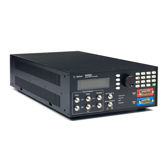
Operation 3.3 N4960A Serial BERT Controller Front Panel The N4960A serial BERT controller front panel indicates the system status and contains the control panel for local operation of the instrument. Figure 6 shows the front panel of the N4960A serial BERT controller. - Page 28 The divided clock output signal also has amplitude, offset, and termination voltage adjustment. By setting the divide ratio to 1, this output can be used as a non-divided clean (non-jittered) clock. Keysight N4960A Serial BERT 17 and 32 Gb/s User Guide...
- Page 29 The Attention LED indicator is lit when an error has occurred. The indicator will not turn off until the error message has been cleared in the Error Log in the System menu. Keysight N4960A Serial BERT 17 and 32 Gb/s User Guide...
-
Page 30: N4960A Serial Bert Controller Rear Panel
Item Description USB Connector The USB connector is a type B USB port that connects the N4960A serial BERT controller to an external PC for remote operation. GPIB Connector The GPIB connector is a general purpose interface bus (GPIB, IEEE 488.1) connection that can be used for remote operation. -
Page 31: N4951A Front Panel
Table 6. N4951A front panel Item Description Ch ID LED The Channel ID LED indicator is lit when connected to the N4960A serial BERT controller. Atten LED The Attention LED indicator is lit when an error has occurred. The indicator will not turn off until the error message has been cleared in the Error Log in the System menu. -
Page 32: N4951A Rear Panel
The D-subminiature connector receives clock signals, control signals, and power supplies from the controller via the 1 meter remote head/controller cable. Label Shows the N4951A option number (-P17 or -P32) and serial number. Keysight N4960A Serial BERT 17 and 32 Gb/s User Guide... -
Page 33: N4951B-D17/-D32 Front Panel
Table 8. N4951B-D17/-D32 front panel Item Description Ch ID LED The Channel ID LED indicator is lit when connected to the N4960A serial BERT controller. Atten LED The Attention LED indicator is lit when an error has occurred. The indicator will not turn off until the error message has been cleared in the Error Log in the System menu. -
Page 34: N4951B-D17/-D32 Rear Panel
1 meter remote head/controller cable. Label Shows the N4951B option number (-D17 or -D32) and serial number. 3.9 N4951B-H17/-H32 Front Panel Figure 12. N4951B-H17/-H32 front panel Keysight N4960A Serial BERT 17 and 32 Gb/s User Guide... -
Page 35: N4951B-H17/-H32 Rear Panel
Table 10. N4951B-H17/-H32 front panel Item Description Ch ID LED The Channel ID LED indicator is lit when connected to the N4960A serial BERT controller. Atten LED The Attention LED indicator is lit when an error has occurred. The indicator will not turn off until the error message has been cleared in the Error Log in the System menu. -
Page 36: N4952A Front Panel
Data Input The differential data inputs are 2.92 mm connectors. Connectors Aux In This connector is reserved for future enhancements. Aux Out The Auxiliary Output connector provides an error trigger. Keysight N4960A Serial BERT 17 and 32 Gb/s User Guide... -
Page 37: N4952A Rear Panel
The D-subminiature connector receives clock signals, control signals, and power supplies from the controller via the 1 meter remote head/controller cable. Label Shows the N4952A option number (-E17 or -E32) and serial number. Keysight N4960A Serial BERT 17 and 32 Gb/s User Guide... -
Page 38: Block Diagram (32 Gb/S System)
3.13 Block Diagram (32 Gb/s system) Figure 16 is a simplified block diagram of the 32 Gb/s system that emphasizes all inputs and outputs. Figure 16. Simplified block diagram (32 Gb/s system) Keysight N4960A Serial BERT 17 and 32 Gb/s User Guide... -
Page 39: Block Diagram (17 Gb/S System)
3.14 Block Diagram (17 Gb/s system) Figure 17 is a simplified block diagram of the 17 Gb/s system that emphasizes all inputs and outputs. Figure 17. Simplified block diagram (17 Gb/s system) Keysight N4960A Serial BERT 17 and 32 Gb/s User Guide... -
Page 40: N4960A Serial Bert Controller
3.15 N4960A Serial BERT Controller 3.15.1 Divided Clock Output The N4960A serial BERT controller has the capability to divide the clock frequency over a broad range of divide ratios and return the divided signal as fully differential non-stressed outputs with adjustable amplitude and offset. -
Page 41: Delayed Clock Output
When used as a clock source for a BERT, the Delayed Clock would generally be used to clock the error detector. The Delayed Clock settings can be controlled programmatically or through the front panel. Keysight N4960A Serial BERT 17 and 32 Gb/s User Guide... -
Page 42: Jittered Clock Output
Before performing measurements, enable the jitter source to be used for the measurement, set the amplitude to 0 UI then perform an auto alignment. Keysight N4960A Serial BERT 17 and 32 Gb/s User Guide... - Page 43 0.150 UI-rms. However, RJ is uncalibrated above 0.025 mUI. The RJ is settable to as low as 0 UI-rms. However, each N4960A-CJ1 will have its own intrinsic RJ minimum, below which, the system cannot achieve the desired value. Typically, this lower limit is between 5 to 12 mUI-rms. It is suggested that the intrinsic RJ be checked for operation in the intended application.
-
Page 44: Low Frequency Band Periodic Or External Jitter Path
Applying excessive amplitude to the external jitter input will overdrive the modulation driver, resulting in non-linear operation or intermittent output (clock slips). The instrument does not detect an external modulation overdrive condition. Keysight N4960A Serial BERT 17 and 32 Gb/s User Guide... -
Page 45: Spread Spectrum Clock Modulation (N4960A-Cj1 Only)45
SSC, the clock synthesizers used in BERTs include SSC. To assure proper tracking of the BERT or sampling scope testing a device with SSC, all three clock outputs of the N4960A-CJ1 controller (Jittered, Delayed and Divided) are modulated with the same SSC signal. -
Page 46: Delayed Clock Input
If the Delayed Clock In is set to External to drive the Delay Clock Outputs of the N4960A and the clock source is set to External, a valid clock signal MUST be applied to the Ext Clock In connector for the Delay Clock Outputs to function properly. -
Page 47: N4960A Serial Bert Controller Output Stages
To meet these requirements, each output stage has an integrated bias tee. On each output of the N4960A serial BERT controller, the amplitude, offset voltage, termination voltage, and AC/DC coupling can be set independently. -
Page 48: Pattern Generator
4 to 17 Gb/s. The differential output has fully adjustable output amplitude, crossover, termination, and DC offset. All features can be controlled through the control panel on the front panel of the N4960A serial BERT controller, remote SCPI commands, or through the N4980A multi-instrument BERT software. 3.16.1... -
Page 49: Error Injection
ErrInjRate command in the Pattern Menu. For example, if 10 selected, a single error is injected approximately every thousand bits. Error injection can also be controlled using the corresponding remote SCPI commands. Keysight N4960A Serial BERT 17 and 32 Gb/s User Guide... -
Page 50: Pattern Generator Output Stage
In this configuration, the pattern generators have independent controls that are identical except for jitter injection and delay control. Refer to Figure 36. Jitter injection is applied to the pattern generator connected to the Jitter connector only. Keysight N4960A Serial BERT 17 and 32 Gb/s User Guide... -
Page 51: N4951B-D17/-D32 Pattern Generator With 5-Tap De-Emphasis
32 Gb/s versions. The de-emphasis head provides designers with the signal pre-distortion capability required for transmitter emulation when characterizing receivers, backplanes, and systems. Figure 22. No de-emphasis Figure 23. De-emphasis equalization applied Keysight N4960A Serial BERT 17 and 32 Gb/s User Guide... -
Page 52: Error Detector
Operation The taps can be adjusted from the front panel of the N4960A, using the Deemphasis functions in the Pat Gen-Jit Menu, or the N4980A multi- instrument BERT software. The N4980A includes a de-emphasis tap weight computation tool that simplifies the process of computing tap weights into the following steps: 1. -
Page 53: Error Detector Input Stage
Figure 24. Error detector input stage 3.17.2 Pattern Selection Patterns are identical to those available for use with the pattern generator. A pattern must first be selected before synchronization can be attempted. Keysight N4960A Serial BERT 17 and 32 Gb/s User Guide... -
Page 54: Synchronization
When the Auto Pattern feature is enabled, Pat Type is set to PRBS and the error detector automatically detects and synchronizes to PRBS patterns. If Auto Pattern cannot determine the pattern type, the message “Unknown” is displayed. Keysight N4960A Serial BERT 17 and 32 Gb/s User Guide... -
Page 55: Alignment
Instead, perform auto-align on a hardware PRBS pattern then switch to the memory based pattern. Changing patterns does not affect alignment. Keysight N4960A Serial BERT 17 and 32 Gb/s User Guide... -
Page 56: Half Rate Clock Architecture
(controller set to 5 GHz), the unit interval is 1 ÷ 10 Gb/s, which equals 100 ps, the time for one bit. Jitter and delay unit intervals can be set at the N4960A serial BERT controller or at the pattern generator and error detector. Therefore, it is... -
Page 57: Jitter Relationship Between Clock Output And Pattern Generator Output
BERT controller relative to the jittered output of a pattern generator connected to the Jitter port. Note that one clock period corresponds to two bit periods. With SJ amplitude set to 0.1 UI in the N4960A serial BERT controller, the SJ amplitude of the pattern generator will be set to 0.2 UI automatically. -
Page 58: Bit Error Rate Tests
For example, 1 error bit out of 1,000,000 total bits would result in a BER of 1e-6 (1/1,000,000). The N4960A serial BERT 17 and 32 Gb/s can be set up to run BER tests using the front panel, remote SCPI commands, or N4980A multi- instrument BERT software. -
Page 59: Accumulated And Instantaneous Ber
The instantaneous BER (iBER) displays the BER at the current instant in time. The iBER is updated at a constant rate, regardless of whether an accumulated BER test is running. Keysight N4960A Serial BERT 17 and 32 Gb/s User Guide... -
Page 60: Control Panel Operation
Navigation through the menus is accomplished with the four softkeys to the right of the display and the rotary knob. Refer to Figure Figure 28. Softkey navigation buttons and rotary knob Keysight N4960A Serial BERT 17 and 32 Gb/s User Guide... - Page 61 If a menu item has a lower-level menu that can be accessed, the SEL softkey appears. Press it to access the corresponding lower-level menu. Refer to Figure Figure 30. Accessing lower-level menus Keysight N4960A Serial BERT 17 and 32 Gb/s User Guide...
-
Page 62: Changing Parameters
The keypad is used if a parameter is a numeric value only. Figure 32 is an example of changing parameters using the rotary knob. Figure 32. Changing parameters using the rotary knob Keysight N4960A Serial BERT 17 and 32 Gb/s User Guide... - Page 63 ENT hardkey on the keypad, or press the softkey corresponding to the associated units label to accept the entry. Refer to Figure Figure 34. Using the numeric keypad Keysight N4960A Serial BERT 17 and 32 Gb/s User Guide...
-
Page 64: Menu Structure
When entered in the pattern generator menu, the 2X conversion factor is automatically applied so the values correspond to the pattern generator output. Keysight N4960A Serial BERT 17 and 32 Gb/s User Guide... - Page 65 Operation Figure 35. Synthesizer, jitter, delay, and divided menu structure Keysight N4960A Serial BERT 17 and 32 Gb/s User Guide...
- Page 66 Operation Figure 36 shows the hierarchical structure of the pattern generator menus. Figure 36. Pattern generator menu structure Keysight N4960A Serial BERT 17 and 32 Gb/s User Guide...
- Page 67 Operation Figure 37 shows the hierarchical structure of the error detector menus. Figure 37. Error detector menu structure Keysight N4960A Serial BERT 17 and 32 Gb/s User Guide...
- Page 68 Operation Figure 38 shows the hierarchical structure of the System menus. Figure 38. System menu structure Keysight N4960A Serial BERT 17 and 32 Gb/s User Guide...
-
Page 69: Menu Label Descriptions
SSC cannot be enabled if the clock source is external. If the clock source conflicts with the SSC enabled state, a message indicating a conflict appears in the N4960A-CJ1 controller display. Selecting Yes to resolve the conflict will set the clock source to an appropriate value. - Page 70 The offset may be limited by the current termination voltage. If the desired offset value conflicts with the current termination value, a message indicating a conflict appears in the N4960A serial BERT controller display. Selecting Yes to resolve the conflict will set the termination to an appropriate value.
- Page 71 SJ1 cannot be enabled if PJ or external jitter (low band) is enabled. If the SJ1 enabled state conflicts with these other jitter sources, a message indicating a conflict appears in the N4960A serial BERT controller display. Selecting Yes to resolve the conflict will disable all conflicting jitter sources.
- Page 72 Periodic Jitter cannot be enabled if any other internal or external jitter source is enabled. If the PJ enabled state conflicts with other jitter sources, a message indicating a conflict appears in the N4960A serial BERT controller display. Selecting Yes to resolve the conflict will disable all other jitter sources.
- Page 73 The offset may be limited by the current termination voltage. If the desired offset value conflicts with the current termination value, a message indicating a conflict appears in the N4960A serial BERT controller display. Selecting Yes to resolve the conflict will set the termination to an appropriate value.
- Page 74 The offset may be limited by the current termination voltage. If the desired offset value conflicts with the current termination value, a message indicating a conflict appears in the N4960A serial BERT controller display. Selecting Yes to resolve the conflict will set the termination to an appropriate value.
- Page 75 The offset may be limited by the current termination voltage. If the desired offset value conflicts with the current termination value, a message indicating a conflict appears in the N4960A serial BERT controller display. Selecting Yes to resolve the conflict will set the termination to an appropriate value.
- Page 76 SJ1 cannot be enabled if PJ or external jitter (low band) is enabled. If the SJ1 enabled state conflicts with these other jitter sources, a message indicating a conflict appears in the N4960A serial BERT controller display. Selecting Yes to resolve the conflict will disable all conflicting jitter sources.
- Page 77 Periodic Jitter cannot be enabled if any other internal or external jitter source is enabled. If the PJ enabled state conflicts with other jitter sources, a message indicating a conflict appears in the N4960A serial BERT controller display. Selecting Yes to resolve the conflict will disable all other jitter sources.
- Page 78 Adjust the impulse response sample of the bit that is three bits after the cursor bit. Feature available in N4960A-CJ1 for pattern generator connected to Jitter connector only. Note that the sum of SJ1, SJ2, RJ, and external jitter low deviation amplitude should not exceed the maximum specified modulation level.
- Page 79 Delay Adjust Delay This sets the amount the clock must be shifted when aligning the pattern generator connected to the Delay connector on the front panel of the N4960A. Resolution is 0.002 UI. Pattern Menu Displays the current pattern name (read only). Use the Pat Type and Name menu items to select the desired pattern.
- Page 80 Resolution is 0.002 UI. TermV Sets the input termination voltage applied to the inputs of the error detector. Resolution is 0.001 V. DRate Displays the current data rate. Keysight N4960A Serial BERT 17 and 32 Gb/s User Guide...
- Page 81 Eye Height: returns the eye height found during auto alignment. Eye Width: returns the eye width found during auto alignment. Last AutoAlign: returns the date and time of the last auto alignment. Keysight N4960A Serial BERT 17 and 32 Gb/s User Guide...
- Page 82 Errs: displays the number of errored bits. Errored 1: displays the number of logic 1 errors. Errored 0: displays the number of logic 0 errors. Elapsed Time: displays the elapsed time of the BER test. Keysight N4960A Serial BERT 17 and 32 Gb/s User Guide...
-
Page 83: Working With Setting Dependencies
Delay port. 3.21 Working with Setting Dependencies The N4960A serial BERT 17 and 32 Gb/s has a number of settings which have a dependency on another setting, noted in the tables above in italic text. - Page 84 Figure 39. Relationship between offset and termination voltage of the clock outputs Keysight N4960A Serial BERT 17 and 32 Gb/s User Guide...
-
Page 85: Verifying Operation
3.22 Verifying Operation The following procedures will familiarize you with the features of the N4960A Serial BERT 17 and 32 Gb/s and provide a quick check of system operation. The procedures all assume starting from a power up preset state. In all cases where the preset value of the setting parameter can be used, no steps are included to set the value. -
Page 86: Initial Settings
0.0 V Units: Volt 2. Turn the N4960A serial BERT controller on and wait until the MAIN menu appears on the display. 3. In the MAIN menu position the arrow next to the Synthesizer Menu label then press the softkey corresponding to the SEL label. -
Page 87: Enabling Sinusoidal Jitter
UI label to set the SJ1 modulation to 0.2 5. In the Data Output Menu position the arrow next to the SJ1Enable label then press the softkey corresponding to the EDIT label. Keysight N4960A Serial BERT 17 and 32 Gb/s User Guide... -
Page 88: Enabling Random Jitter (N4960A-Cj1 Controller Only)
Data Output Menu. A random jittered eye pattern should now be displayed on the high speed sampling scope similar to the one shown in Figure Keysight N4960A Serial BERT 17 and 32 Gb/s User Guide... -
Page 89: Enabling Spread Spectrum Clock (N4960A-Cj1 Controller Only)
6. Press the softkey corresponding to the SEL label to accept the entry and return to the Synthesizer Menu. A waveform similar to the one shown in Figure 44 should now be displayed on the high speed sampling scope. Keysight N4960A Serial BERT 17 and 32 Gb/s User Guide... -
Page 90: Bit Error Rate Test
3.22.6 Bit Error Rate Test 1. Connect the equipment as shown in Figure 2. Tighten cables to 8 lbf-in (90 N-cm). Figure 45. Setup for BER test Keysight N4960A Serial BERT 17 and 32 Gb/s User Guide... - Page 91 17. When the bit error rate test has completed, position the arrow next to the Results label then press the softkey corresponding to the SEL label. 18. Ensure that Errs reads 0.000e0. Keysight N4960A Serial BERT 17 and 32 Gb/s User Guide...
-
Page 92: Setting Frequency And Output Amplitude
3.23 Setting Frequency and Output Amplitude The following procedure shows how to set the frequency and clock output amplitude of the N4960A serial BERT controller. The settings are output to either the Jitter or Delay clock connectors on the front panel of the N4960A serial BERT controller. -
Page 93: Setting Random Jitter Injection (N4960A-Cj1 Controller Only)
The following procedure shows how to set up a single sinusoidal jitter path. The settings are output to the Jitter clock connector on the front panel of the N4960A serial BERT controller and to a pattern generator connected to the Jitter port. -
Page 94: Setting External Jitter High Frequency Injection
4. In the Dly Clk Out Menu position the arrow next to the Amp label then press the softkey corresponding to the EDIT label. 5. Adjust the delayed clock output amplitude using the rotary knob or the numeric keypad. Keysight N4960A Serial BERT 17 and 32 Gb/s User Guide... -
Page 95: Setting Divided Clock Output
3.20.2 Changing Parameters for instructions on how to use the rotary knob or numeric keypad to make changes. 6. Press the softkey corresponding to the EXIT label to accept the entry. Keysight N4960A Serial BERT 17 and 32 Gb/s User Guide... -
Page 96: Event/Error Log
SCPI PJ frequency setting. See Section 6.10.1. INTERNAL Used to indicate the 10MHz reference clock is set to Internal EXTERNAL Used to indicate the 10MHz reference clock is set to External Keysight N4960A Serial BERT 17 and 32 Gb/s User Guide... -
Page 97: Applications
Applications 4 Applications 4.1 Introduction The N4960A serial BERT 17 and 32 Gb/s performs basic BER and jitter tolerance testing or general receiver characterization applications. In a general BERT application, the outputs would be configured as follows: Jitter connector is used to drive the pattern generator. Stress can be applied for jitter tolerance testing or other receiver characterization testing. -
Page 98: Testing Transceivers Used In Fibre Channel Networks
BERT software, can also provide jitter tolerance tests for accurate characterization. 1. Turn the N4960A serial BERT controller on and wait until the MAIN menu appears on the display. 2. In the MAIN menu position the arrow next to the Synthesizer Menu label then press the softkey corresponding to the SEL label. - Page 99 23. Position the arrow next to the Results label then press the softkey corresponding to the SEL label. 24. View accumulated BER (aBER), total errors (Errs), one errors (Errored 1), zero errors (Errored 0), and measurement time (Elapsed Time). Keysight N4960A Serial BERT 17 and 32 Gb/s User Guide...
- Page 100 Applications Keysight N4960A Serial BERT 17 and 32 Gb/s User Guide...
-
Page 101: Performance Specifications
Output Configuration All Outputs Differential, with amplitude, offset, and termination voltage adjustment (can be used single ended without terminating unused outputs) Amplitude Range 300 mV to 1.7 V (p-p), single ended Keysight N4960A Serial BERT 17 and 32 Gb/s User Guide... - Page 102 (Waveshape of divided clock slower than ≈ 1 MHz will be differentiated) Delayed Clock Delay Range 0 to ±1,000 UI Delayed Clock Delay Resolution 1 mUI Connector Type All signals except 10 MHz Ref In/Out 10 MHz Ref In, Out Keysight N4960A Serial BERT 17 and 32 Gb/s User Guide...
-
Page 103: N4960A Clock Source/Bert Controller Jitter Specifications
With no pattern generator head connected to jitter port: 1 Hz to 200 MHz With an N4951A/B pattern generator head connected to Jitter port: 1 Hz to 150 MHz, over-programmable to 200 MHz Keysight N4960A Serial BERT 17 and 32 Gb/s User Guide... - Page 104 N4951A/B pattern generator 0 to 7 mUI rms, >29 to 31.5 Gb/s head connected to the Jitter Over-programmable to 25 mUI port: RJ Crest Factor 14 minimum (p-p to rms ratio) Keysight N4960A Serial BERT 17 and 32 Gb/s User Guide...
- Page 105 Front panel output frequency 0.001 to 50 UI for frequency ≤62.5 kHz 0.001 to (3.125E6/ PJ Frequency) for frequency >62.5 kHz to > 2 to 16 GHz 17 MHz (see Figure Figure Figure Keysight N4960A Serial BERT 17 and 32 Gb/s User Guide...
-
Page 106: Maximum N4960A Clock Modulation Range Without Pg
5.2.1 Maximum N4960A Clock Modulation Range without PG Connected Figure 46. Maximum N4960A JITTER CLOCK OUTPUT modulation amplitude when no remote pattern generator head is attached to the Jitter port Keysight N4960A Serial BERT 17 and 32 Gb/s User Guide... -
Page 107: Maximum N4960A Clock Modulation Range With Pg
5.2.2 Maximum N4960A Clock Modulation Range with PG Connected Figure 47. Maximum N4960A JITTER CLOCK OUTPUT modulation amplitude when a remote pattern generator head is attached to the Jitter port Figure 48. Maximum N4951A/B Pattern Generator Remote Head DATA OUTPUT modulation... -
Page 108: N4951A/N4951B Pattern Generator Specifications
12 ps typical, 15 ps maximum 1, 4 N4951B-D32 12 ps typical, 15 ps maximum 2, 4 N4951B-H17 16 ps typical, 20 ps maximum N4951B-H32 15 ps typical, 19 ps maximum Keysight N4960A Serial BERT 17 and 32 Gb/s User Guide... - Page 109 N4960A driven with an external clock, for example Keysight E8257D Data Delay spec applies only to a pattern generator connected to the Delay port N4951B pattern generator heads are only supported on Keysight N4960A controllers with serial numbers higher than US53083001, otherwise an N4960A controller upgrade is required Cursor amplitudes are specified relative to the preceding cursor;...
- Page 110 Atten – error condition occurred and logged in Error Log On – data output on Jitter injection specifications (SJ, PJ, RJ, Ext) apply only to a pattern generator connected to the Jitter port. Keysight N4960A Serial BERT 17 and 32 Gb/s User Guide...
-
Page 111: N4952A-E17/N4952A-E32 Error Detector Specifications
Data Loss – no data detected Sync Loss – not synchronized to the incoming data stream Atten – error condition occurred and recorded into Error Log At ≤ 28 Gb/s. Keysight N4960A Serial BERT 17 and 32 Gb/s User Guide... - Page 112 Performance Specifications Keysight N4960A Serial BERT 17 and 32 Gb/s User Guide...
-
Page 113: Gpib Interface
1987. New York, NY, 1987. A GPIB interface requires that all devices on a common bus have different addresses. The address of the N4960A serial BERT 17 and 32 Gb/s is set up using the System Settings menu. The range is 0 to 30. -
Page 114: Usb Interface
(hot swapping). Connect a Type-A to Type-B 5 pin cable from the USB port of the PC controller to the USB port on the rear panel of the N4960A serial BERT controller. Keysight N4960A Serial BERT 17 and 32 Gb/s User Guide... -
Page 115: Usb Driver
6.2.1 USB Driver Installation of the appropriate driver is required. The N4960A serial BERT controller USB port can be accessed from a PC as a virtual COM port (VCP). Virtual COM port drivers cause the USB device to appear as an additional COM port available to the PC. -
Page 116: Remote Command Syntax
• The command o :SOURce:FREQuency • Can be written in lowercase o :source:frequency • And it can be shortened o :SOUR:FREQ Keysight N4960A Serial BERT 17 and 32 Gb/s User Guide... -
Page 117: Ieee Common Commands
Remote Operation 6.4 IEEE Common Commands The IEEE 488.2 standard has a list of reserved commands that must be implemented by all instruments using the standard. The N4960A serial BERT controller implements all of the required commands, listed in Table Table 31. -
Page 118: Scpi Mandated Commands
Returns the number of errors in the queue. 6.6 SCPI Protocol Description The N4960A serial BERT controller supports a simple SCPI syntax. SCPI has an associated hierarchy with it. The top level is referred to as the Root mode. SCPI remembers the current hierarchy so you do not need to repeat it for subsequent commands. -
Page 119: Scpi Numeric Parameters And Optional Units
6.8 Pattern Generator Channelization Pattern generators can be connected to the jitter or delay connectors on the front panel of the N4960A controller. You can also connect a pattern generator to the jitter connector and another pattern generator to the delay connector for dual pattern generation. - Page 120 For commands that set parameters, if there is a mismatch in one or more of the remote heads in the channel list, then error code -221, “Settings Conflict” is returned and no action is taken on the command. Keysight N4960A Serial BERT 17 and 32 Gb/s User Guide...
-
Page 121: Command Conventions
A legal program data element was parsed but could not be executed because the value was outside the legal range as defined by the device. -224, "Illegal parameter value" Used where exact value, from a list of possible values, was expected. Keysight N4960A Serial BERT 17 and 32 Gb/s User Guide... -
Page 122: Settings Conflict" Used For Settings Dependencies
PJ Amplitude. The PJ Amplitude is a function of the PJ Frequency. If the controlling program attempts to change the PJ Frequency such that it is incompatible with the current PJ Amplitude, the N4960A serial BERT controller will respond with a AMPL_LIMIT_WARN instrument... -
Page 123: N4960A Serial Bert Controller Device Commands
0.7 V. Example :OUTD:AMPL 750mV Command :OUTDelay:AMPLitude? Description Return the amplitude value of the output delay logic level. The range is 0.3 V to 1.7 V. Example :OUTD:AMPL? 0.750V Keysight N4960A Serial BERT 17 and 32 Gb/s User Guide... - Page 124 DC without any dependencies. Example :OUTD:COUP DC Command :OUTDelay:COUPling? Description Return the position of the internal switch. The returned string is AC or Example :OUTD:COUP? Keysight N4960A Serial BERT 17 and 32 Gb/s User Guide...
- Page 125 Example :OUTD:DEL 1;*OPC? Command :OUTDelay:DELay? Description Return the value of the output delay. The data delay range is –1000 UI to 1000 UI. Example :OUTD:DEL? 1.000UI Keysight N4960A Serial BERT 17 and 32 Gb/s User Guide...
- Page 126 If the coupling is set to DC, then offset can be changed. Example :OUTD:OFFS 2V Command :OUTDelay:OFFSet? Description Return the offset value of the output delay logic level. The range is –2.4 V to +2.4 V. Example :OUTD:OFFS? 2.000V Keysight N4960A Serial BERT 17 and 32 Gb/s User Guide...
- Page 127 Turn the output delay clock ON or OFF. The default is OFF. Example :OUTD:OUTP on Command :OUTDelay:OUTPut? Description Return the status of the output delay clock. The returned string is either ON or OFF. Example :OUTD:OUTP? Keysight N4960A Serial BERT 17 and 32 Gb/s User Guide...
- Page 128 Example :OUTD:TERM 1.3V Command :OUTDelay:TERMination? Description Return the termination value of the output delay logic level. The range is –2.4 V to +2.4 V. Example :OUTD:TERM? 1.300V Keysight N4960A Serial BERT 17 and 32 Gb/s User Guide...
- Page 129 0 V to change coupling to AC or a setting conflict error message will be generated. If coupling is already set to AC, it can be changed to DC without any dependencies. Example :OUTJ:COUP DC Keysight N4960A Serial BERT 17 and 32 Gb/s User Guide...
- Page 130 (indicated by the return of the number “1”). The *OPC? query command can be appended to the command as shown below. Example :OUTJ:JITT:EXT high;*OPC? Keysight N4960A Serial BERT 17 and 32 Gb/s User Guide...
- Page 131 (milli Unit Interval). The default value/unit is 1 UI/V. Example :OUTJ:JITT:EXT:LBG 2UI/V;*OPC? Command :OUTJitter:JITTer:EXTernal:LBGain? Description Return the value of the external low band amplitude. The range is 0.001 UI/V to 50 UI/V. Example .:OUTJ:JITT:EXT:LBG? 2.000UI/V Keysight N4960A Serial BERT 17 and 32 Gb/s User Guide...
- Page 132 The *OPC? query command can be appended to the command as shown below. Example :OUTJ:JITT:PER ON;*OPC? Command :OUTJitter:JITTer:PERiodic? Description Return the status of the periodic jitter. The returned string is either ON or OFF. Example :OUTJ:JITT:PER? Keysight N4960A Serial BERT 17 and 32 Gb/s User Guide...
- Page 133 The *OPC? query command can be appended to the command as shown below. Example :OUTJ:JITT:PER:AMP 1UI;*OPC? Command :OUTJitter:JITTer:PERiodic:AMPLitude? Description Return the value of the periodic jitter amplitude. The range is 0 UI to 100 UI. Example :OUTJ:JITT:PER:AMP? 1.000UI Keysight N4960A Serial BERT 17 and 32 Gb/s User Guide...
- Page 134 Example :OUTJ:JITT:PER:FREQ 4MHz Command :OUTJitter:JITTer:PERiodic:FREQuency? Description Return the value of the periodic jitter frequency. The range is 1 Hz to 17 MHz. Example :OUTJ:JITT:PER:FREQ? 4000000 Hz Keysight N4960A Serial BERT 17 and 32 Gb/s User Guide...
- Page 135 Example :OUTJ:JITT:RAND on Command :OUTJitter:JITTer:RANDom?. Description Return the status of the random jitter source. The returned string is either ON or OFF. Example :OUTJ:JITT:RAND? Keysight N4960A Serial BERT 17 and 32 Gb/s User Guide...
- Page 136 Return the value of the random level. The range is 0 UI-rms to 0.150 UI- rms. This is the over-programming range. Refer to 5 Performance Specifications for the maximum specified range. Example :OUTJ:JITT:RAND:AMPL? 0.100UI-rms Keysight N4960A Serial BERT 17 and 32 Gb/s User Guide...
- Page 137 (lowband) is enabled or a setting conflict error message will be generated. Example :OUTJ:JITT:SIN1 on Command :OUTJitter:JITTer:SINusoidal1? Description Return the status of SJ1. The returned string is either ON or OFF. Example :OUTJ:JITT:SIN1? Keysight N4960A Serial BERT 17 and 32 Gb/s User Guide...
- Page 138 Return the value of the SJ1 amplitude. The range is 0 UI to 1.0 UI. This is the over-programming range. Refer to 5 Performance Specifications for the maximum specified range. Example :OUTJ:JITT:SIN1:AMPL? 1.000UI Keysight N4960A Serial BERT 17 and 32 Gb/s User Guide...
- Page 139 Return the value of the SJ1 frequency. The range is 1 Hz to 200 MHz. This is the over-programming range. Refer to 5 Performance Specifications for the maximum specified range. Example :OUTJ:JITT:SIN1:FREQ? 100000000 Hz Keysight N4960A Serial BERT 17 and 32 Gb/s User Guide...
- Page 140 Example :OUTJ:JITT:SIN2 on Command :OUTJitter:JITTer:SINusoidal2? Description Return the status of SJ2. The returned string is either ON or OFF. Example :OUTJ:JITT:SIN2? Keysight N4960A Serial BERT 17 and 32 Gb/s User Guide...
- Page 141 Return the value of the SJ2 amplitude. The range is 0 UI to 1.0 UI. This is the over-programming range. Refer to 5 Performance Specifications for the maximum specified range. Example :OUTJ:JITT:SIN2:AMPL? 1.000UI Keysight N4960A Serial BERT 17 and 32 Gb/s User Guide...
- Page 142 Return the value of the SJ2 frequency. The range is 1 Hz to 200 MHz. This is the over-programming range. Refer to 5 Performance Specifications for the maximum specified range. Example :OUTJ:JITT:SIN2:FREQ? 100000000 Hz Keysight N4960A Serial BERT 17 and 32 Gb/s User Guide...
- Page 143 If the coupling is set to DC, then offset can be changed. Example :OUTJ:OFFS 2V Command :OUTJitter:OFFSet? Description Return the DC offset voltage at the clock outputs. The range is –2.4 V to +2.4 V. Example :OUTJ:OFFS? 2.000V Keysight N4960A Serial BERT 17 and 32 Gb/s User Guide...
- Page 144 Turn the output jitter clock ON or OFF. The default is OFF. Example :OUTJ:OUTP on Command :OUTJitter:OUTPut? Description Return the status of the output jitter clock. The returned string is either ON or OFF. Example :OUTJ:OUTP? Keysight N4960A Serial BERT 17 and 32 Gb/s User Guide...
- Page 145 Example :OUTJ:TERM 1.3V Command :OUTJitter:TERMination? Description Return the termination voltage of the 50 Ω input port. The range is –2.4 V to +2.4 V. Example :OUTJ:TERM? 1.300V Keysight N4960A Serial BERT 17 and 32 Gb/s User Guide...
- Page 146 0 V to change coupling to AC or a setting conflict error message will be generated. If coupling is already set to AC, it can be changed to DC without any dependencies. Example :OUTJ:COUP DC Keysight N4960A Serial BERT 17 and 32 Gb/s User Guide...
- Page 147 Set the divider value for the divided clock output from 1 to 99999999 in increments of 1. The default value is 4. Example :OUTS:DIV 6 Command :OUTSubrate:DIVider? Description Return the divider value. The range is 1 to 99999999. Example :OUTS:DIV? Keysight N4960A Serial BERT 17 and 32 Gb/s User Guide...
- Page 148 If the coupling is set to DC, then offset can be changed. Example :OUTS:OFFS 2V Command :OUTSubrate:OFFSet? Description Return the offset value of the divided clock output logic level. The range is –2.4 V to +2.4 V. Example :OUTS:OFFS? 2.000V Keysight N4960A Serial BERT 17 and 32 Gb/s User Guide...
- Page 149 Turn the divided clock output ON or OFF. The default is OFF. Example :OUTS:OUTP on Command :OUTSubrate:OUTPut? Description Return the status of the divided clock output. The returned string is either ON or OFF. Example :OUTS:OUTP? Keysight N4960A Serial BERT 17 and 32 Gb/s User Guide...
- Page 150 Example :OUTS:TERM 1.3V Command :OUTSubrate:TERMination? Description Return the termination value of the subrate output logic level. The range is –2.4 V to +2.4 V. Example :OUTS:TERM? 1.300V Keysight N4960A Serial BERT 17 and 32 Gb/s User Guide...
- Page 151 Return the value of the external delay clock frequency. If :SOURce:DCLock:PATH is set to SYSTem, then the frequency of the internal clock is returned. The default is the frequency value of the internal clock. Example :SOUR:DCL:FREQ? 2500MHz Keysight N4960A Serial BERT 17 and 32 Gb/s User Guide...
- Page 152 :SOUR:DCL:PATH SYST Command :SOURce:DCLock:PATH? Description Return the status of the delay clock source path. The returned string is either SYST (internal delay source) or EXT (external delay source). Example :SOUR:DCL:PATH? SYST Keysight N4960A Serial BERT 17 and 32 Gb/s User Guide...
- Page 153 Example :SOUR:FREQ 2.5GHz;*OPC? Command :SOURce:FREQuency? Description Return the value of the internal clock frequency. The range is 1 to 16 GHz (without remote heads connected). Example :SOUR:FREQ? 2500000000 Hz Keysight N4960A Serial BERT 17 and 32 Gb/s User Guide...
- Page 154 The *OPC? query command can be appended to the command as shown below. Example :SOUR:FREQ:CW 2.5GHz;*OPC? Command :SOURce:FREQuency:CW? Description Return the value of the source CW frequency. The range is 1 to 16 GHz. Example :SOUR:FREQ:CW? 2500000000 Hz Keysight N4960A Serial BERT 17 and 32 Gb/s User Guide...
- Page 155 Set the frequency path to INTernal for using the internal source or EXTernal for using an external source. The default is INTernal. The N4960A BERT Controller should be disabled before setting the clock source to EXTernal. If spread spectrum clock (SSC) is enabled, then a setting conflict error message will be generated and the clock source cannot be set to EXTernal.
- Page 156 (“REF,INTERNAL” and “REF,EXTERNAL”) respectively. If the 10 MHz Reference is using an External source and there is a loss of signal, a loss of signal error will be generated (“REF,LOS”). Keysight N4960A Serial BERT 17 and 32 Gb/s User Guide...
- Page 157 Turn the spread spectrum clock (SSC) ON or OFF. The default is OFF. The clock source must be set to INTernal before enabling the N4960A Serial BERT 17 and 32 Gb/s. If the clock source is set to EXTernal, a setting conflict error message is generated and SSC cannot be enabled.
- Page 158 10000 PPM in 1 PPM increments. The default value/unit is 5000 PPM. Example :SOUR:SSCL:DEV 10000ppm Command :SOURce:SSCLocking:DEViation? Description Return the deviation value of the spread spectrum clock. The range is 0 PPM (parts per million) to 10000 PPM. Example :SOUR:SSCL:DEV? 10000PPM. Keysight N4960A Serial BERT 17 and 32 Gb/s User Guide...
- Page 159 1 Hz to 50000 Hz. Example :SOUR:SSCL:FREQ? 50000 Hz Command :SOURce:SSCLocking:TYPE Description Set the spread spectrum clock direction to DOWN, UP, or CENTer. The default is DOWN. Example :SOUR:SSCL:TYPE UP Keysight N4960A Serial BERT 17 and 32 Gb/s User Guide...
- Page 160 Return the status of the spread spectrum clock type. The returned string is DOWN, UP, or CENTer. Example :SOUR:SSCL:TYPE? Command :SYSTem:DATE Description Set the current date. The format is YYYY,MM,DD. Command :SYSTem:DATE? Description Return the current date. Example :SYST:DATE? 2011,09,02 Keysight N4960A Serial BERT 17 and 32 Gb/s User Guide...
- Page 161 If the queue is empty, the response is 0. Example :SYST:ERR:COUN? Keysight N4960A Serial BERT 17 and 32 Gb/s User Guide...
- Page 162 The serial number format is country (2 characters), year (number of years after 1960), week number (2 digits), and sequence number (4 digits). Example :SYST:HEAD? N4951A-P32,02.00,03.00.00.20,US52340206:N4952A- E32,02.00,03.00.01.02, US52340224: Keysight N4960A Serial BERT 17 and 32 Gb/s User Guide...
- Page 163 Example :SYST:LLOC The following message is displayed on the front panel: LOCAL LOCKOUT FRONT PANEL DISABLED. Command :SYSTem:LOCal Description Places instrument from local lockout to local mode. Example :SYST:LOC Keysight N4960A Serial BERT 17 and 32 Gb/s User Guide...
- Page 164 Example :SYSTem:PRESet;*OPC? Command :SYSTem:STATe:RECall Description Recall a previously saved state from 1 to 5. Command :SYSTem:STATe:SAVE Description Save a system state to a storage number from 1 to 5. Keysight N4960A Serial BERT 17 and 32 Gb/s User Guide...
- Page 165 Command :SYSTem:TIME Description Set the current time. The format is HH,MM,SS. Command :SYSTem:TIME? Description Return the current time. Command :SYSTem:VERSion? Description Return current version of SCPI commands. Example :SYST:VERS? 1999.0 Keysight N4960A Serial BERT 17 and 32 Gb/s User Guide...
-
Page 166: Pattern Generator Device Commands
Remote Operation 6.12 Pattern Generator Device Commands Jitter and spread spectrum clock can only be set using the N4960A serial BERT controller clock SCPI commands. Therefore, SCPI values must be set to half of the value desired on the pattern generator outputs. - Page 167 (relative to post-cursor1) in 0.1 dB increments. The optional unit is dB. This command applies to the N4951B-D17/-D32 only. Example :PG:DATA:DEEM:POST2 0 Sets the postcursor 2 to 0 dB for the pattern generator connected to channel 0 (Jitter) only. Keysight N4960A Serial BERT 17 and 32 Gb/s User Guide...
- Page 168 (relative to post-cursor1) in 0.1 dB increments. The optional unit is dB. This command applies to the N4951B-D17/-D32 only. Example :PG:DATA:DEEM:POST3 0 Sets the postcursor 3 to 0 dB for the pattern generator connected to channel 0 (Jitter) only. Keysight N4960A Serial BERT 17 and 32 Gb/s User Guide...
- Page 169 The optional unit is dB. This command applies to the N4951B-D17/-D32 only. Example :PG:DATA:DEEM:PREC 0 (@ 0) Sets the precursor to 0 dB for the pattern generator connected to channel 0 (Jitter) only. Keysight N4960A Serial BERT 17 and 32 Gb/s User Guide...
- Page 170 1.25 V 0.8 V -1.3 V -2.0 V Example :PG:DATA:LLEV lvpecl (@ 0:1) Sets the logic level to LVPECL on pattern generators connected to channel 0 (Jitter) and channel 1 (Delay). Keysight N4960A Serial BERT 17 and 32 Gb/s User Guide...
- Page 171 The units are V and mV. The default value/unit is 0.5 V. Example :PG:DATA:LLEV:AMPL 800mV Sets the amplitude to 800 mV for the pattern generator connected to channel 0 (Jitter) only. Keysight N4960A Serial BERT 17 and 32 Gb/s User Guide...
- Page 172 –2.0 V to 2.0 V in 0.005 V increments. The units are V and mV. The default value/unit is 0.0 V. Example :PG:DATA:LLEV:OFFS 2V (@ 1) Sets the DC offset to 2 V for the pattern generator connected to channel 1 (Delay) only. Keysight N4960A Serial BERT 17 and 32 Gb/s User Guide...
- Page 173 –2.0 V to 2.0 V in 0.005 V increments. The units are V and mV. The default value/unit is 0.0 V. Example :PG:DATA:LLEV:TERM 1.3V (@ 0) Sets the termination voltage to 1.3 V for the pattern generator connected to channel 0 (Jitter) only. Keysight N4960A Serial BERT 17 and 32 Gb/s User Guide...
- Page 174 *RST command, or performing an instrument preset. Example :PG:DATA:OUTP on (@ 0,1) Sets the data outputs to on for the pattern generators connected to channel 0 (Jitter) and channel 1 (Delay). Keysight N4960A Serial BERT 17 and 32 Gb/s User Guide...
- Page 175 1 must be specified or the command will be sent to channel 0 (Jitter) and an error will be returned. Example :PG:DATA:OUTP:DEL 1000UI (@ 1) Sets the delay to 1000UI for the pattern generator connected to channel 1 (Delay) only. Keysight N4960A Serial BERT 17 and 32 Gb/s User Guide...
- Page 176 OFF. The rate is set using the :PG:DATA:PATTern:ERRInjection:RATE command. Example :PG:DATA:PATT:ERRI on Sets the error injection to on for the pattern generator connected to channel 0 (Jitter) only. Keysight N4960A Serial BERT 17 and 32 Gb/s User Guide...
- Page 177 The default is E-3 (at least 1 error bit in 1000 bits). Example :PG:DATA:PATT:ERRI:RATE E-6 Sets the error injection to 1 error bit in 1000000 bits for the pattern generator connected to channel 0 (Jitter) only. Keysight N4960A Serial BERT 17 and 32 Gb/s User Guide...
- Page 178 Inject a single error. A single error can be injected regardless of whether error injection is on or off. Example :PG:DATA:PATT:ERRI:SING (@ 1) Injects a single error from the pattern generator connected to channel 1 (Delay). Keysight N4960A Serial BERT 17 and 32 Gb/s User Guide...
- Page 179 PRBS2^7-1, PRBS2^9-1, PRBS2^10-1, PRBS2^11-1, PRBS2^15-1, PRBS2^23-1, PRBS2^29-1, PRBS2^31-1, PRBS2^33-1, PRBS2^35-1, PRBS2^39-1, PRBS2^41-1, PRBS2^45-1, PRBS2^47-1, PRBS2^49-1, PRBS2^51-1 Queries the list of PRBS patterns of the pattern generator connected to channel 0 (Jitter) only. Keysight N4960A Serial BERT 17 and 32 Gb/s User Guide...
- Page 180 Return the list of all available user patterns, which are the patterns created via the N4980A multi-instrument BERT software and uploaded to the N4960A serial BERT controller. These patterns have a filename containing eight characters with a three character extension (.usr).
- Page 181 NONInvert. The default is NONInvert. Example :PG:DATA:PATT:POL INV Sets the pattern polarity to inverted for the pattern generator connected to channel 0 (Jitter) only. Keysight N4960A Serial BERT 17 and 32 Gb/s User Guide...
- Page 182 Set the data crossover from 35% to 65% in 1% increments (integers only). The default is 50%. Example :PG:DATA:XOV 35 Sets the crossover to 35% for the pattern generator connected to channel 0 (Jitter) only. Keysight N4960A Serial BERT 17 and 32 Gb/s User Guide...
- Page 183 Return the current data rate. The data rate is two times the clock frequency. Example :PG:DRATe? 10000000000 bps Queries the current data rate of the pattern generator connected to channel 0 (Jitter) only. Keysight N4960A Serial BERT 17 and 32 Gb/s User Guide...
-
Page 184: Error Detector Device Commands
The default is ON. Example :ED:DATA:AAL:CAAL:DEL on Command :ED:DATA:AALign:CAALign:DELay? Description Return the status of the sampling delay. The returned string is either ON or OFF. Example :ED:DATA:AAL:CAAL:DEL? Keysight N4960A Serial BERT 17 and 32 Gb/s User Guide... - Page 185 SVOL is turned OFF. Example :ED:DATA:AAL:CAAL:SVOL on Command :ED:DATA:AALign:CAALign:SVOLtage? Description Return the status of the sampling threshold voltage. The returned string is either ON or OFF. Example :ED:DATA:AAL:CAAL:SVOL? Keysight N4960A Serial BERT 17 and 32 Gb/s User Guide...
- Page 186 The optional units are V and mV. The default value/unit is 0.02 V. Example :ED:DATA:AAL:CAAL:SVST 20mV Command :ED:DATA:AALign:CAALign:SVSTep? Description Return the sampling threshold voltage step size. The range is 0.005 V to 0.02 V. Example :ED:DATA:AAL:CAAL:SVST? 0.02V Keysight N4960A Serial BERT 17 and 32 Gb/s User Guide...
- Page 187 (indicated by the return of the number “1”). The *OPC? query command can be appended to the command as shown below. Example :ED:DATA:AAL:EXEC;*OPC? Keysight N4960A Serial BERT 17 and 32 Gb/s User Guide...
- Page 188 However, the results provide a good first-level indicator of the eye quality. If an auto alignment has not been performed before initiating this command and delay is enabled, N/A will be returned. Example :ED:DATA:AAL:RES:EWID? 0.560UI Keysight N4960A Serial BERT 17 and 32 Gb/s User Guide...
- Page 189 Return the current status of the accumulated BER measurement. The returned string is IDLE, RUNNing, or DONE. After the accumulation is done and the accumulated BER results are cleared, the query result is IDLE. Example :ED:DATA:ACC? DONE Keysight N4960A Serial BERT 17 and 32 Gb/s User Guide...
- Page 190 Clear the accumulated BER results. This command will only clear results if the accumulated BER measurement is not running. Example :ED:DATA:ACC:CLR Command :ED:DATA:ACCumulation:RESults:ABER? Description Return the accumulated BER results. The maximum bit count is approximately 3.4e+38. Example :ED:DATA:ACC:RES:ABER? 1.0000e-8 Keysight N4960A Serial BERT 17 and 32 Gb/s User Guide...
- Page 191 (IDLE, RUNNing, or DONE). The maximum bit count is approximately 3.4e+38. Example :ED:DATA:ACC:RES:ALL? 2.0000e10,0.000e0,0.000e0,10.000S,RUNNING Command :ED:DATA:ACCumulation:RESults:BITS? Description Return the total accumulated number of bits. Example :ED:DATA:ACC:RES:BITS? 9.3000e10 Keysight N4960A Serial BERT 17 and 32 Gb/s User Guide...
- Page 192 0000:00:59:10 Command :ED:DATA:ACCumulation:RESults:ERONes? Description Return the accumulated number of 1s resulting in bit errors. Example :ED:DATA:ACC:RES:ERON? 5.1500e2 Command :ED:DATA:ACCumulation:RESults:ERRors? Description Return the accumulated number of bit errors. Example :ED:DATA:ACC:RES:ERR? 1.0200e3 Keysight N4960A Serial BERT 17 and 32 Gb/s User Guide...
- Page 193 (duration determined by total number of accumulated bits as set by the :ED:DATA:ACCumulation:SCONfig:BITS command) ERRors (duration determined by total number of accumulated errors as set by the :ED:DATA:ACCumulation:SCONfig:ERRors command) The default is MANual. Example :ED:DATA:ACC:SCON BITS Keysight N4960A Serial BERT 17 and 32 Gb/s User Guide...
- Page 194 1e8 through 1e17. The default is 1e9. Example :ED:DATA:ACC:SCON:BITS E8 Command :ED:DATA:ACCumulation:SCONfig:BITS? Description Return the number of bits defined for the duration of the measurement. The range is 1e8 through 1e17. Example :ED:DATA:ACC:SCON:BITS? Keysight N4960A Serial BERT 17 and 32 Gb/s User Guide...
- Page 195 When the stop criteria mode is set to ERRors, this command defines the duration of the measurement by the number of accumulated error bits. The range is 1 through 99999999. The default is 1. Example :ED:DATA:ACC:SCON:ERR 10 Keysight N4960A Serial BERT 17 and 32 Gb/s User Guide...
- Page 196 Start an accumulated BER measurement. Starting a BER accumulation does not automatically clear accumulated BER results. Always use the CLR command before starting a BER accumulation to clear results. Example :ED:DATA:ACC:CLR :ED:DATA:ACC:STAR Keysight N4960A Serial BERT 17 and 32 Gb/s User Guide...
- Page 197 (indicated by the return of the number “1”). The *OPC? query command can be appended to the command as shown below. Example :ED:DATA:INP:DEL 1000UI;*OPC? Keysight N4960A Serial BERT 17 and 32 Gb/s User Guide...
- Page 198 –1.0 V to 1.0 V in 0.001 V increments. The optional units are V and mV. The default value/unit is 0 V. The sampling voltage can be set manually or automatically by the auto alignment process. Example :ED:DATA:INP:SVOL 1V Keysight N4960A Serial BERT 17 and 32 Gb/s User Guide...
- Page 199 V and mV. The default value/unit is 0 V. Example :ED:DATA:INP:VTER 2V Command :ED:DATA:INPut:VTERmination? Description Return the input termination voltage setting. The range is –2.0 V to 2.0 V. Example :ED:DATA:INP:VTER? 2.000V Keysight N4960A Serial BERT 17 and 32 Gb/s User Guide...
- Page 200 Return the status of the auto pattern for PRBS patterns. The returned string is either ON or OFF. Example :ED:DATA:PATT:APAT? Command :ED:DATA:PATTern:LIST? Description Return the list of all available patterns including factory, PRBS, and user. Keysight N4960A Serial BERT 17 and 32 Gb/s User Guide...
- Page 201 Return the list of all available user patterns, which are the patterns created via the N4980A multi-instrument BERT software and uploaded to the N4960A serial BERT controller. These patterns have a filename containing eight characters with a three character extension (.usr).
- Page 202 (indicated by the return of the number “1”). The *OPC? query command can be appended to the command as shown below. Example :ED:DATA:PATT:NAME PRBS2^7-1;*OPC? Command :ED:DATA:PATTern:NAME? Description Return the selected data pattern name. Example :ED:DATA:PATT:NAME? PRBS2^7-1 Keysight N4960A Serial BERT 17 and 32 Gb/s User Guide...
- Page 203 ALL_ONES (decision point is too low), or ALL_ZEROS (decision point is too high). If all ones or all zeros are detected, the Data Loss LED on the front panel of the error detector turns on. Example :ED:DATA:STAT? Keysight N4960A Serial BERT 17 and 32 Gb/s User Guide...
- Page 204 :ED:DATA:SYNChronize:EXECute command is initiated (MANual). Example :ED:DATA:SYNC:MODE AUTO Command :ED:DATA:SYNChronize:MODE? Description Return the synchronization mode setting. The returned string is either AUTO or MANual. Example :ED:DATA:SYNC:MODE? AUTO Keysight N4960A Serial BERT 17 and 32 Gb/s User Guide...
- Page 205 AUTO mode. An automatic synchronization will not be executed if in MANual mode. The synchronization threshold rates are as follows: The default is E-2. Example :ED:DATA:SYNC:STHR E-3 Keysight N4960A Serial BERT 17 and 32 Gb/s User Guide...
- Page 206 Description Return the synchronization threshold rate. The synchronization threshold rates are as follows: Example :ED:DATA:SYNC:STHR? Command :ED:DATA:SYNChronize:TYPE? Description Return the synchronization type. The default value is NORMal. Example :ED:DATA:SYNC:TYPE? NORM Keysight N4960A Serial BERT 17 and 32 Gb/s User Guide...
- Page 207 Remote Operation Command :ED:DRATe? Description Return the current data rate. Example :ED:DRATe? 10000000000 bps Keysight N4960A Serial BERT 17 and 32 Gb/s User Guide...
-
Page 208: Command Summary
Remote Operation 6.14 Command Summary This section provides a summary of SCPI commands for the N4960A serial BERT controller, pattern generator, and error detector. 6.14.1 N4960A Serial BERT Controller Command Summary The N4960A serial BERT controller device commands are summarized in Table Table 35. - Page 209 <unit> ::= 1 Hz to 200 MHz, resolution = 1 Hz :OUTJitter:JITTer:SINusoidal2:FREQuency? :OUTJitter:OFFSet value <unit> ::= –2.4 V to +2.4 V, resolution = 0.005 V :OUTJitter:OFFSet? :OUTJitter:OUTPut {ON | OFF} :OUTJitter:OUTPut? Keysight N4960A Serial BERT 17 and 32 Gb/s User Guide...
- Page 210 :SOURce:FREQuency:PATH {INTernal | EXTernal} :SOURce:FREQuency:PATH? :SOURce:ROSCillator:PATH {AUTO | INTernal | EXTernal} :SOURce:ROSCillator:PATH? :SOURce:SSCLocking {ON | OFF} :SOURce:SSCLocking? :SOURce:SSCLocking:DEViation value <unit> ::= 0 PPM to 10000 PPM, resolution = 1 PPM Keysight N4960A Serial BERT 17 and 32 Gb/s User Guide...
- Page 211 Execute a system preset. :SYSTem:STATe:RECall Recall a previously stored state. :SYSTem:STATe:SAVE Save a system state. :SYSTem:TIME? Responds with current time. :SYSTem:TIME Set the current time. :SYSTem:VERSion? Responds with current version of SCPI commands. Keysight N4960A Serial BERT 17 and 32 Gb/s User Guide...
-
Page 212: Pattern Generator Command Summary
<unit> ::= –2.0 V to +2.0 V, resolution = 0.005 V :PG:DATA:LLEVel:TERMination? :PG:DATA:OUTPut {ON | OFF} :PG:DATA:OUTPut? :PG:DATA:OUTPut:DELay value <unit> ::= –2000 UI to 2000 UI, resolution = 0.002 UI (applies to channel 1 only) Keysight N4960A Serial BERT 17 and 32 Gb/s User Guide... - Page 213 5.FPT |K28-7.FPT } :PG:DATA:PATTern:NAME? :PG:DATA:PATTern:POLarity {INVert | NONInvert} :PG:DATA:PATTern:POLarity? :PG:DATA:XOVer value <unit> ::= 25% to 75%, resolution = 1% :PG:DATA:XOVer? :PG:DRATe? Responds with the current data rate (two times the clock frequency) Keysight N4960A Serial BERT 17 and 32 Gb/s User Guide...
-
Page 214: Error Detector Command Summary
{E8 | E9 | E10 | E11 | E12 | E13 | E14 | E15 | E16 | E17} :ED:DATA:ACCumulation:SCONfig:BITS? :ED:DATA:ACCumulation:SCONfig:DUR value <unit> ::= 1 s to 9999999 s, resolution = 1 s :ED:DATA:ACCumulation:SCONfig:DUR? :ED:DATA:ACCumulation:SCONfig:ERRors value ::= 1 to 99999999, resolution = 1 Keysight N4960A Serial BERT 17 and 32 Gb/s User Guide... - Page 215 K28-5.FPT |K28-7.FPT } :ED:DATA:PATTern:NAME? :ED:DATA:PATTern:POLarity {INVert | NONInvert} :ED:DATA:PATTern:POLarity? :ED:DATA:STATus? Responds with the status of the error detector alignment: [OK | ALL_ONES | ALL_ZEROS] :ED:DATA:SYNChronize:EXECute Momentary command to perform a manual synchronization Keysight N4960A Serial BERT 17 and 32 Gb/s User Guide...
- Page 216 {E-2 | E-3 | E-4 | E-5 | E-6 | E-7 | E-8 | E-9} :ED:DATA:SYNChronize:STHReshold? :ED:DATA:SYNChronize:TYPE? NORMal :ED:DRATe? Responds with the current data rate (two times the clock frequency) Keysight N4960A Serial BERT 17 and 32 Gb/s User Guide...
-
Page 217: Programming Example
The open-source PyVISA package enables fast and easy GPIB and USB instrument control. The example program below demonstrates some popular methods of interfacing with the N4960A serial BERT 17 and 32 Gb/s. The program was written for a 32 Gb/s system. Contact support@Keysight Technologies.com... - Page 218 E32 = True print "found head: " + edType + " serial number " + edSN # reset the instrument, if desired if resetN4960A: print "resetting instrument:", N4960A.write("*RST") N4960A.write("*OPC?") print "done" Keysight N4960A Serial BERT 17 and 32 Gb/s User Guide...
- Page 219 # turn on internal clock and set frequency to 7.0125GHz (equiv to 14.025Gb/s) print "setting clock:", N4960A.write(":SOUR:FREQ:PATH INT; *OPC?") print N4960A.ask(":SOUR:FREQ:PATH?").strip("\n"), N4960A.write(":SOUR:FREQ %.3fGHz; *OPC?" % 7.0125) print N4960A.ask(":SOUR:FREQ?").strip("\n") # set delayed N4960A clock outputs on, to 1Vpp and 0.5UI delay print "delayed clock outputs:", N4960A.write(":OUTD:AMPL 1V") print N4960A.ask(":OUTD:AMPL?").strip("\n"), N4960A.write(":OUTD:OUTP ON") print N4960A.ask(":OUTD:OUTP?").strip("\n"), N4960A.write(":OUTD:DEL 0.5UI;...
- Page 220 N4960A.ask(":OUTJ:JITT:PER?").strip("\n"), N4960A.write(":OUTJ:JITT:SIN1 OFF") print "SJ1:", print N4960A.ask(":OUTJ:JITT:SIN1?").strip("\n"), N4960A.write(":OUTJ:JITT:SIN2 OFF") print "SJ2:", print N4960A.ask(":OUTJ:JITT:SIN2?").strip("\n"), N4960A.write(":OUTJ:JITT:RAND OFF") print "RJ:", print N4960A.ask(":OUTJ:JITT:RAND?").strip("\n") # turn on PJ and adjust to 0.32UI at 2.4MHz Keysight N4960A Serial BERT 17 and 32 Gb/s User Guide...
- Page 221 N4960A.write(":OUTJ:JITT:SIN2 ON") N4960A.write(":OUTJ:JITT:SIN2:FREQ 150MHz") print N4960A.ask(":OUTJ:JITT:SIN2:FREQ?").strip("\n").strip(" "), N4960A.write(":OUTJ:JITT:SIN2:AMPL 0.15UI") print N4960A.ask(":OUTJ:JITT:SIN2:AMPL?").strip("\n") # turn on RJ and adjust to 0.02UI rms print "RJ:", N4960A.write(":OUTJ:JITT:RAND ON") print N4960A.ask(":OUTJ:JITT:RAND?").strip("\n"), N4960A.write(":OUTJ:JITT:RAND:AMPL 0.02") print N4960A.ask(":OUTJ:JITT:RAND:AMPL?").strip("\n") Keysight N4960A Serial BERT 17 and 32 Gb/s User Guide...
- Page 222 # set the pattern to PRBS9, non-inverted, no error injection # this could take a while for user patterns N4960A.write(":PG:DATA:PATT:NAME PRBS2^9-1; *OPC?") print N4960A.ask(":PG:DATA:PATT:NAME?").strip("\n"), N4960A.write(":PG:DATA:PATT:POL NONI") print N4960A.ask(":PG:DATA:PATT:POL?").strip("\n"), N4960A.write(":PG:DATA:PATT:ERRI OFF") print "error inject:", print N4960A.ask(":PG:DATA:PATT:ERRI?").strip("\n") Keysight N4960A Serial BERT 17 and 32 Gb/s User Guide...
- Page 223 "executing.. please wait..", N4960A.write(":ED:DATA:AAL:EXEC; *OPC?") # this could take a while print "..done" print "Auto-align result: 0/1 Threshold =", print N4960A.ask(":ED:DATA:AAL:RES:EHE?").strip("\n"), print ", Data delay =", print N4960A.ask(":ED:DATA:AAL:RES:EWID?").strip("\n") print "Eye height =", Keysight N4960A Serial BERT 17 and 32 Gb/s User Guide...
- Page 224 = " + N4960A.ask(":ED:DATA:ACC:RES:ELAP?").strip("\n") print "Bits = " + N4960A.ask(":ED:DATA:ACC:RES:BITS?").strip("\n") print "Errors = " + N4960A.ask(":ED:DATA:ACC:RES:ERR?").strip("\n") print "Errored 1's = " + N4960A.ask(":ED:DATA:ACC:RES:ERON?").strip("\n") print "Errored 0's = " + N4960A.ask(":ED:DATA:ACC:RES:ERZ?").strip("\n") Keysight N4960A Serial BERT 17 and 32 Gb/s User Guide...
- Page 225 Auto-align result: 0/1 Threshold = 0.340V , Data delay = 0.840UI Eye height = 0.340V , Eye width = 0.840UI sync: SYNC sync: SYNC measuring BER Accumulation status is IDLE Accumulation status is IDLE Keysight N4960A Serial BERT 17 and 32 Gb/s User Guide...
- Page 226 Accumulation status is IDLE Accumulation results: = 0.0000e0 Time = 0000:00:00:10 Bits = +1.4307e11 Errors = +0.0000e0 Errored 1's = +0.0000e0 Errored 0's = +0.0000e0 error queue: 0, "No error" Keysight N4960A Serial BERT 17 and 32 Gb/s User Guide...
-
Page 227: Programming Tips
Some commands to control the N4960A serial BERT 17 and 32 Gb/s may take a long time to execute completely. These are listed in Table Table 38. N4960A serial BERT commands that should be accompanied by *OPC? or *WAI Command :SOURce:FREQuency... -
Page 228: Example Using *Opc
The first command will be executed, the *WAI will delay until the command has been completed, and then the final command will be executed. N4960A.write(":OUTD:DEL 0.5UI; *WAI; :OUTD:OUTP ON") Keysight N4960A Serial BERT 17 and 32 Gb/s User Guide... -
Page 229: Communication Timeouts
Remote Operation 6.16.3 Communication Timeouts Most SCPI commands of the N4960A serial BERT 17 and 32 Gb/s are processed quickly and return within milliseconds. A few commands require a longer time to take place and process. The user should use “*OPC?” or “*WAI” after the SCPI command or “*OPC”... - Page 230 The bus interface timeout needs to be modified to ensure that synchronization can complete without triggering a communication timeout. If a communication timeout occurs before an operation complete Keysight N4960A Serial BERT 17 and 32 Gb/s User Guide...
- Page 231 (approximately 6 seconds). If a communication timeout has occurred, repeated execution of an auto alignment will cause the instrument USB or GPIB remote interface to lock and requires a power cycle to recover. Keysight N4960A Serial BERT 17 and 32 Gb/s User Guide...
- Page 232 Remote Operation Keysight N4960A Serial BERT 17 and 32 Gb/s User Guide...
-
Page 233: Returning The N4960A To Keysight
Returning the N4960A to Keysight 7 Returning the N4960A to Keysight If the N4960A serial BERT fails system verification and you cannot correct the problem, return it to Keysight Technologies for repair following the steps shown below. 1. Record all symptoms. - Page 234 Returning the N4960A to Keysight Keysight N4960A Serial BERT 17 and 32 Gb/s User Guide...
-
Page 235: Appendix A Preset State
5 GHz Jittered Clock Amplitude 0.700 V Jittered Clock Coupling Jittered Clock Offset Jittered Clock Output Enable Jittered Clock Termination LB Gain 1.0 UI/V PJ Amplitude 0.0 UI PJ Enable Keysight N4960A Serial BERT 17 and 32 Gb/s User Guide... - Page 236 CUSTom Name PRBS2^7-1 Offset 0.0 V Output Enable Pattern PRBS2^7-1 Pattern Invert Pattern Type PRBS PJ Amplitude 0.0 UI PJ Enable PJ Frequency 100 kHz Post Cursor 1 +00.00 dB Keysight N4960A Serial BERT 17 and 32 Gb/s User Guide...
- Page 237 Termination 0.0 V Applies to pattern generator connected to Jitter connector (channel 0) on front panel of N4960A only. Applies to pattern generator connected to Delay connector (channel 1) on front panel of N4960A only. Applies to N4951B-D17/-D32 pattern generators only.
- Page 238 20 mV Set Delay Set Sample Voltage Stop Manual Stop Criteria - Bits Stop Criteria - Duration 10 seconds Stop Criteria - Errors Sync Mode Auto Termination Voltage 0.0 V Keysight N4960A Serial BERT 17 and 32 Gb/s User Guide...
- Page 240 This information is subject to change without notice. © Copyright Keysight Technologies 2012-2019 Edition 9.0, April 2019 www.keysight.com...
Need help?
Do you have a question about the N4960A and is the answer not in the manual?
Questions and answers