Table of Contents
Advertisement
Quick Links
Advertisement
Table of Contents

Related Manuals for Keysight Technologies N4373E


Summary of Contents for Keysight Technologies N4373E
- Page 1 Keysight N4373E Lightwave Component Analyzer Setup Guide...
- Page 2 AND ANY INFORMATION CONTAINED ment (EULA), a copy of which can be found HEREIN, INCLUDING BUT NOT LIMITED TO at http://www.keysight.com/find/sweula. THE IMPLIED WARRANTIES OF The license set forth in the EULA represents Keysight N4373E Lightwave Component Analyzer Setup Guide...
-
Page 3: Table Of Contents
Unpacking the Lightwave Component Analyzer Mounting the Test Set and the Network Analyzer Preparing the Test Head Preparing the Network Analyzer Mounting the Network Analyzer on the Test Head Setting Up the Lightwave Component Analyzer Keysight N4373E Lightwave Component Analyzer Getting Started Guide... -
Page 5: Introduction
Keysight N4373E Lightwave Component Analyzer Setup Guide Introduction Documentation General Safety Considerations Optical Test Set Front and Rear Panels / 14... -
Page 6: Documentation
Introduction Documentation The documentation for the Keysight N4373E Lightwave Component Analyzer consists of • The documentation for the Keysight network analyzer. This documentation i s on the hard disk of the network analyzer. Refer to it for using the network analyzer for electrical to electrical measurements, or for the configuration of the network analyzer. -
Page 7: General Safety Considerations
The laser radiation symbol. This warning symbol is marked on products which have a laser output. The Off-On symbols are used to mark the positions of the instrument power operating switch. Keysight N4373E Lightwave Component Analyzer Setup Guide... - Page 8 Any interruption of the protective conductor inside or outside of the instrument is likely to make the instrument dangerous. Intentional interruption is prohibited. Keysight N4373E Lightwave Component Analyzer Setup Guide...
- Page 9 Always use the three-prong AC power cord supplied with this CAUTION instrument. Failure to ensure adequate earth grounding by not using this cord may cause instrument damage. Keysight N4373E Lightwave Component Analyzer Setup Guide...
-
Page 10: Initial Safety Information
IEC 60825-1 (2014) we recommend that you stick the laser safety labels, in your language, onto a suitable location on the outside of the instrument where they are clearly visible to anyone using the instrument. Keysight N4373E Lightwave Component Analyzer Setup Guide... - Page 11 • The laser module has built-in safety circuitry which will disable the optical output in the case of a fault condition. • Refer servicing only to qualified and authorized personnel Keysight N4373E Lightwave Component Analyzer Setup Guide...
-
Page 12: Line Power Requirements
The type of power cable shipped with each instrument depends on the country of destination. Please refer to “Power Cords” section of the N4373E User’s Guide (Manual Part No. 4373E-90B01) for the part numbers of available power cables. -
Page 13: Environmental Information
Directive Annex I, this product is classed as a "Monitoring and Control instrumentation" product. Do not dispose in domestic household waste. To return unwanted products, contact your local Keysight office, or see about https://about.keysight.com/en/companyinfo/environment/ta keback.shtml for more information. Keysight N4373E Lightwave Component Analyzer User’s Guide... -
Page 14: Optical Test Set Front And Rear Panels
Optical Test Set Front and Rear Panels 2-port PNA version Figure 2 Front Panel For further information on the front panel of the network analyzer, please refer to the documentation supplied with the network analyzer. Keysight N4373E Lightwave Component Analyzer Setup Guide... - Page 15 +4 dBm and +14 dBm. This input has reduced sensitivity. Port B Output port of the optical test set. It is used to connect the optical test set to the PNA. Keysight N4373E Lightwave Component Analyzer Setup Guide...
- Page 16 Network analyzer Port 1 This is an S parameter measurement port of the network analyzer. Depending on the S parameters of the measurement this can be either an RF input or an RF output. Keysight N4373E Lightwave Component Analyzer Setup Guide...
-
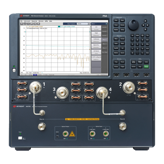
Page 17: 4-Port Pna Version
Introduction 4-port PNA version Figure 3 Front Panel For further information on the front panel of the network analyzer, please refer to the documentation supplied with the network analyzer. Keysight N4373E Lightwave Component Analyzer Setup Guide... - Page 18 +4 dBm and +14 dBm. This input has reduced sensitivity. Port B This is the output port of the optical test set. It is used to connect the optical test set to the PNA. Keysight N4373E Lightwave Component Analyzer Setup Guide...
- Page 19 Network analyzer Port 4 This is an S parameter measurement port of the network analyzer. Depending on the S parameters of the measurement this can be either an RF input or an RF output. Keysight N4373E Lightwave Component Analyzer Setup Guide...
-
Page 20: Rear Panel
The software on the network analyzer uses the USB port to control the optical test set. External Input Plug in an external laser source. Line power cable Plug in your power cable here. connector Keysight N4373E Lightwave Component Analyzer Setup Guide... -
Page 21: Setting Up The Instrument
Keysight N4373E Lightwave Component Analyzer Setup Guide Setting Up the Instrument Unpacking the Lightwave Component Analyzer / 22 Mounting the Test Set and the Network Analyzer / 24 Setting Up the Lightwave Component Analyzer / 30... -
Page 22: Unpacking The Lightwave Component Analyzer
1x 1005-1027 FC/FC feedthrough adapter for narrow key • -050 external optical source input • 1x PMF patch cord 1.0 m FC/APC narrow key • 1x 08154-61723 optical adapter FC (equivalent to 81000NI) Keysight N4373E Lightwave Component Analyzer Setup Guide... - Page 23 Refer also to the contents list of the network analyzer. If anything is missing or defective, contact your nearest Keysight Technologies sales office. If the shipment was damaged, contact the carrier, then contact the nearest Keysight Technologies sales office. Keysight N4373E Lightwave Component Analyzer Setup Guide...
-
Page 24: Mounting The Test Set And The Network Analyzer
N4373-25271 to the rear side of the test head. Use the screws 0515-0433 and a Torx T20 screwdriver to attach the rear brackets N4373-25290 and N4373-25291 to the right and left bracket adapter. Keysight N4373E Lightwave Component Analyzer Setup Guide... - Page 25 Turn the test head on its side and use a Pozidrive size 2 screwdriver to mount the adjustable feet 0403-1166 to the left and right brackets. Turn the test head back to its normal position. Keysight N4373E Lightwave Component Analyzer Setup Guide...
-
Page 26: Preparing The Network Analyzer
Turn the Network Analyzer on its side. Unlock the feet to remove them from the bottom of the network analyzer. Using a Torx T20 screwdriver, remove the 2 lower rear feet from the rear panel of the network analyzer Keysight N4373E Lightwave Component Analyzer Setup Guide... -
Page 27: Mounting The Network Analyzer On The Test Head
For the combined weight, please consult the specifications (refer to the “General Characteristics” section of the N4373E User’s Guide, Manual Part No. 4373E-90B01), and the user’s documentation for the network analyzer). Put the network analyzer on top of the test head and align it with the mounting slots of the rear brackets. - Page 28 Setting Up the Instrument Use a Torx T20 screwdriver to attach the side bars 83427-21274 with the screws 0515-1269 to the left and right sides of the two instruments. Keysight N4373E Lightwave Component Analyzer Setup Guide...
- Page 29 10 Attach the adhesive trim covers to the left and right side bars to cover the screws. 11 Use the 13mm wrench to level the adjustable feet to the other feet of the test head. Use the upper nuts to lock the feet in place. Keysight N4373E Lightwave Component Analyzer Setup Guide...
-
Page 30: Setting Up The Lightwave Component Analyzer
8710-1765) to remove the top two rigid cables from the connectors. • Re-connect the rigid cables in a vertical position and fasten them using the same torque wrench as before. Keysight N4373E Lightwave Component Analyzer Setup Guide... - Page 31 For information on handling, calibrating or cleaning RF connectors, NOTE please refer to the “User’s and Service Guide Keysight Technologies N4697E/F 1.85 mm Flexible Cables for Test Ports”, available on the Keysight website. For further information on the Adapter, please refer to the “User’s and Service Guide Keysight Technologies 85130H Rugged 1.85 mm to...
- Page 32 Port 2 of the 2-port network analyzer or, respectively, to Port 4 of the 4-port network analyzer. Holding the adapter with the spanner wrench, use the 20 mm torque wrench from the calibration kit to tighten both connections. Keysight N4373E Lightwave Component Analyzer Setup Guide...
- Page 33 Make sure to connect only matching connector types to the optical test CAUTION set: connecting a straight connector to an angled port, or vice versa, will damage both interfaces. Keysight N4373E Lightwave Component Analyzer Setup Guide...
- Page 34 15 On the rear, connect the network analyzer to the optical test set using the supplied USB cable. 16 Connect the power cables. 17 Continue with “Performance Quick Check” section or “Starting the Lightwave Component Analyzer” section of the N4373E User’s Guide (Manual Part No. 4373E-90B01). Keysight N4373E Lightwave Component Analyzer Setup Guide...
- Page 36 This information is subject to change without notice. © Keysight Technologies 2020 Edition 2.0, January 2020 Printed in Malaysia www.keysight.com...
Need help?
Do you have a question about the N4373E and is the answer not in the manual?
Questions and answers