
Related Manuals for Siemens SENTRON ATC6300


Summary of Contents for Siemens SENTRON ATC6300
- Page 1 Manual SENTRON Monitoring Devices 3KC ATC6300 Transfer Control Device Edition 03/2018 siemens.com/3KC...
- Page 3 ___________________ Introduction ___________________ General information ___________________ SENTRON Applications ___________________ Product description Transfer switching equipment and load transfer switches ___________________ 3KC ATC6300 transfer control Functions device ___________________ Installation Manual ___________________ Connection ___________________ Operation ___________________ Parameterization ___________________ Commissioning ___________________ MODBUS communication ___________________ Accessories ___________________ Technical specifications...
- Page 4 Note the following: WARNING Siemens products may only be used for the applications described in the catalog and in the relevant technical documentation. If products and components from other manufacturers are used, these must be recommended or approved by Siemens. Proper transport, storage, installation, assembly, commissioning, operation and maintenance are required to ensure that the products operate safely and without any problems.
-
Page 5: Table Of Contents
Reference documents ....................... 8 1.2.3 Technical Support ........................8 General information ..........................9 Properties of the ATC6300 transfer control device ..............9 Compatible Siemens SENTRON switching devices ............... 11 Applications ............................13 Transfer control ........................13 3.1.1 Network/network application ....................13 3.1.2... - Page 6 Technical specifications of the Siemens SENTRON switching devices in accordance with IEC 60947-6-1 (IEC only) ....................82 7.3.3.1 Typical operating times of the Siemens SENTRON switching devices in accordance with IEC 60947-6-1 (IEC only) ....................86 7.3.4 Connection of 3VA molded case circuit breakers ..............89 7.3.4.1...
- Page 7 Table of contents 7.3.4.2 Connection of 3VA molded case circuit breakers - SEO520 (IEC) ........90 7.3.5 Connection of 3VL molded case circuit breakers ..............92 7.3.5.1 Connection of molded case circuit breakers 3VL 160X - 3VL 800 MO (IEC) ......92 7.3.5.2 Connection of molded case circuit breakers 3VL 1250-1600 MO (IEC), 3VL 1200-1600 MO (UL), 3VL SEO (UL, IEC) ....................
- Page 8 Table of contents MODBUS communication ........................147 11.1 General information on MODBUS..................147 11.2 MODBUS RTU protocol ....................... 148 11.3 MODBUS ASCII protocol ..................... 149 11.4 MODBUS functions ......................151 11.5 Password entry by means of MODBUS ................156 11.6 Data library ...........................
-
Page 9: Introduction
Introduction About this documentation Purpose of this manual The information contained in this manual enables you to install, operate and use the 3KC ATC6300 transfer control device. The manual contains information on: ● Product specifications ● Installation ● Operation ● Configuration ●... -
Page 10: Product-Specific Information
1.2.2 Reference documents Further documents and information You will find further information in the following documents: Title Article number Link Siemens switching devices home Siemens switching devices page (http://www.siemens.com/switching-devices) Operating instructions 3KC ATC6300 3ZW1012-0KC00-1A 3KC ATC6300 transfer control device transfer control device (https://support.industry.siemens.com/cs/ww/en/view/1097... -
Page 11: General Information
General information Properties of the ATC6300 transfer control device The ATC6300 transfer control device, in combination with Siemens circuit breakers with motor operators (ACB, MCCB) or remotely operated transfer switching equipment (RTSE), enables a transfer between a main and an alternative power source. The stability of the power supply is analyzed by means of voltage taps upstream of the switching devices. - Page 12 ● Voltage unbalance ● Minimum and maximum frequency Area of application The ATC6300 transfer control device can be used in conjunction with Siemens switching devices, e.g. in the following industrial areas in which a continuous power supply needs to be ensured.
-
Page 13: Compatible Siemens Sentron Switching Devices
General information 2.2 Compatible Siemens SENTRON switching devices Compatible Siemens SENTRON switching devices The ATC6300 permits the transfer between two supply sources using the following Siemens products. Note A motor operator must be implemented to transfer between circuit breakers. Precise connection diagrams can be obtained from chapter Connection (Page 65). For further information about testing, please refer to chapter Accessories for switching devices (Page 76). -
Page 15: Applications
These can make and conduct short-circuit currents, and also break them in the event of an overload. The ATC6300 functions as class CB transfer switching equipment in connection with two Siemens 3VA or 3VL molded case circuit breakers with motor operators, and in connection with two 3WL or 3WT air circuit breakers. -
Page 16: Network/Generator Application
Applications 3.1 Transfer control 3.1.2 Network/generator application For the network/generator application the load is normally connected to the main source (Line 1). Following a deviation in the voltage or frequency, and after the defined delay time, a start signal is sent to the generator (Line 2). If the generator supplies the desired voltage, the load is transferred to the secondary source (generator) until the main source supplies the desired supply quality. -
Page 17: Controlling The Switching Devices
Applications 3.2 Controlling the switching devices Controlling the switching devices The ATC6300 can control various devices for automatic transfer switching. How the control of the switching devices can be implemented is shown below. ● Depending on the type of transfer device used, the appropriate wiring diagram shall be used (see chapter Connection (Page 65)), as well as the programmable inputs/outputs on the ATC6300 (see chapter Description and designation of the outputs (Page 110)). -
Page 18: Controlling Remotely Operated Transfer Switching Equipment
Applications 3.3 Voltage control 3.2.2 Controlling remotely operated transfer switching equipment The control of remotely operated transfer switching equipment (single motor operator) is similar to the control of circuit breakers with motor operator, however it requires only three outputs (close Line 1, open both lines, close Line 2) and two inputs for the status of the transfer switching equipment. - Page 19 Applications 3.3 Voltage control ● In the case of three- or two-phase power supplies you can choose whether you want to monitor the phase-to-phase voltage, the phase-to-neutral voltage, or both (P02.07). In each case, the rated voltage set in P02.01 must be equal to the phase-to-phase voltage. ●...
-
Page 21: Product Description
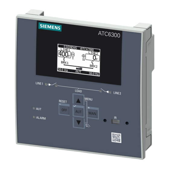
Product description Product description User interface 3KC ATC6300 transfer control device Manual, 03/2018, L1V30535632002A-01... - Page 22 Product description 4.1 Product description Status LEDs The LEDs on the operator panel indicate the status of the device and/or the controlled switching devices. The meaning of the various LEDs is shown in the following table: LED ON LED OFF LED FLASHING ①...
- Page 23 Product description 4.1 Product description Keys Function ③ Key ▲ Pressing this key switches between menu pages. Within the menus, it is used to switch between • the parameters. ④ MAN / + Pressing the MAN / + key for at least 0.5 seconds selects the Manual operating mode. •...
-
Page 24: Menu Navigation
Product description 4.2 Menu navigation Menu navigation The following section describes the front-mounted LCD. This display enables the device to be parameterized (see chapter Parameterization (Page 115)). In addition, measured values relating to voltage and frequency can be read from it. Description of the main menu Procedure for opening the main menu Simultaneously pressing the ▲... - Page 25 Product description 4.3 Description of the main menu Description of the symbols The symbols are used as shortcuts, with which the display pages of the measurements can be retrieved faster. They enable a jump to be made directly to the selected group of messages. From there, it is possible to scroll forward or back as usual.
-
Page 26: Navigation Through The Main Menu
Product description 4.4 Navigation through the main menu Navigation through the main menu Press ▲ or ▼ to scroll through the main menu functions in a clockwise / counter-clockwise direction. Alternatively, you can also scroll clockwise / counter-clockwise through the options using the + / - keys . - Page 27 Product description 4.5 Display pages of the ATC6300 The submenu L-L Voltage shows the voltage between the phases. The menu shows ● the voltages currently being measured ● the frequency of both lines currently being measured ● the current operating mode This view is not available in single-phase supplies.
- Page 28 Product description 4.5 Display pages of the ATC6300 It shows ● the threshold values of the voltage between L-L and between L-N (if set) ● the threshold values of the minimum and maximum frequency If a threshold value is exceeded/undershot, it is shown with a black background, which means that it is possible to check in real time in the Control Thresholds menu which parameter of the voltage supply is causing problems.
- Page 29 Product description 4.5 Display pages of the ATC6300 This shows: ● how often one of the two sources has been switched to the automatic and manual mode ● how often the alarms A03 and A04 (see chapter Alarms (Page 46)) have been active ●...
- Page 30 Product description 4.5 Display pages of the ATC6300 Expansion Modules ① Slot 2 ② Slot 1 The Expansion Modules submenu indicates whether additional modules (e.g. communication modules) are plugged into the ATC6300, and which ones. It shows how the ATC is being supplied (via AC or DC) and whether the USB front interface has been inserted.
- Page 31 Product description 4.5 Display pages of the ATC6300 Inputs In the Inputs submenu the functions of the individual inputs can be viewed in detail. Here, too, only those inputs that are shown with a black background are activated. Outputs In the Outputs submenu the functions of the individual outputs can be viewed in detail. Here, too, only those outputs that are shown with a black background are activated.
- Page 32 On the "Systeminfo" page you can read out information regarding the software and the device. The SIEMENS ATC6300 field can be freely designated by means of Menu P01, Parameter P01.10 (see chapter P01 - Settings (Page 121)). Information page 2 On the "Systeminfo"...
- Page 33 The symbols for generator and network applications change according to the application that is set. The designation in the SIEMENS ATC6300 field can be freely set by the user. (Menu P01, Parameter P01.10 (see chapter P01 Settings (Page 121)).
- Page 34 Product description 4.5 Display pages of the ATC6300 Counters This page is only visible if the Counters function has been activated. In the Counters menu the status of active counters can be viewed. It shows how often the defined status has occurred. The designation (Test1 in this example) and the unit (WM1 in this example) can be freely defined by the user.
- Page 35 Product description 4.5 Display pages of the ATC6300 Setup menu This menu is only visible if the symbol was selected on the main menu. Using the setup menu, you can modify the parameters on the device. You can find a detailed description in chapter Parameterization (Page 115).
-
Page 36: Scrolling Through The Display
Product description 4.5 Display pages of the ATC6300 4.5.2 Scrolling through the display pages You can scroll through any display pages on the ATC6300 using the ▲ or ▼ keys. Note Several pages are available for some menus. Using the example of the Systeminfo menu, the following instructions show how additional pages can be displayed: 1. -
Page 37: Functions
Functions The following chapter contains information on: ● Basic functions ● Advanced functions Basic functions 5.1.1 Setting the real-time clock The virtual calendar clock of the ATC6300 must be set when the device is first commissioned. You can select whether the clock is to be reset after each device restart. This can be set using parameter P01.02 (refer to chapter P01 Settings (Page 121)). -
Page 38: Password Protection
Functions 5.1 Basic functions 5.1.2 Password protection Access to the ATC6300 can be denied by means of a password. Both the physical access to the device and the access via MODBUS can be protected with a password. Note Default setting On new devices the factory setting is as follows: one password is activated for the user level, one for the advanced level, and one password for remote access. -
Page 39: Password Protection Against Remote Access (Remote Password)
Functions 5.1 Basic functions If an attempt is made to select a parameter that is not available, the following message is displayed: Advanced password With the advanced password, all parameters can be changed and all commands executed. 5.1.2.2 Password protection against remote access (remote password) To restrict remote access to the device via MODBUS, a 4-digit numerical code can also be assigned for this purpose. - Page 40 Functions 5.1 Basic functions After you have clicked on the symbol, the following window appears: Procedure for password entry: 1. Change the value of the selected digit with the ▲ and ▼ keys. 2. Move from digit to digit with the + and – keys. 3.
-
Page 41: Keypad Lock
Functions 5.1 Basic functions 5.1.3 Keypad lock In addition to password protection, the operator panel of the ATC6300 can also be disabled. The purpose of this is to prevent any unintended changes being made to the ATC6300 by accidentally touching the keys. The keypad lock can be implemented in two different ways: ●... -
Page 42: Activation Of The Keypad Lock By Means Of A Key Combination On The Operator Panel
Functions 5.1 Basic functions 5.1.3.2 Activation of the keypad lock by means of a key combination on the operator panel Procedure for locking and unlocking the keypad: 1. While holding down the ▲ key, press the ▼ key three times without releasing it at the end 2. -
Page 43: Expandability By Modules
Functions 5.1 Basic functions 5.1.4 Expandability by modules On the back of the ATC6300 there are two slots for expansion modules. These can be used to extend the functionality of the device. For additional information on installing the expansion modules, please refer to the chapter Inserting an expansion module (Page 43). -
Page 44: Enabling Additional Resources
Functions 5.1 Basic functions 5.1.4.1 Enabling additional resources The expansion modules provide additional resources that can be used via the corresponding setup menus. Note Availability during physical absence of modules The setup menus for the expansions are also available if the modules are not physically present, i.e. -
Page 45: Inserting An Expansion Module
Press on the expansion module until it latches into place. You will find further information on the expansion modules in the operating instructions ● ATC6 DI/DO expansion modules (https://support.industry.siemens.com/cs/ww/en/view/109751947) ● ATC6 Ethernet expansion modules (https://support.industry.siemens.com/cs/ww/en/view/109751948) ● ATC6 RS485 expansion modules (https://support.industry.siemens.com/cs/ww/en/view/109751949) -
Page 46: Behavior Of The Atc6300 After Inserting A Module
Functions 5.1 Basic functions 5.1.4.3 Behavior of the ATC6300 after inserting a module As soon as the power supply is connected to the ATC6300, it automatically detects a new expansion module. If the system configuration deviates from the last configuration stored (if, for example, a module has been inserted or removed), the ATC6300 prompts the user to confirm the new configuration. -
Page 47: Communication Comx
Functions 5.1 Basic functions 5.1.5 Communication COMx No more than two communication modules identified as COMn may be connected to the ATC6300. The communications setup menu therefore contains two sections (n=1 ... 2) with parameters for the configuration of the communication ports. The communication channels are completely independent, both in terms of the hardware (type of physical interface) and in terms of the communication protocol. -
Page 48: Alarms
Functions 5.1 Basic functions 5.1.6 Alarms The ATC6300 has 18 predefined alarms and can also display an additional 4 user alarms. On occurrence of an alarm, an alarm symbol appears on the display with an identification code and the description of the alarm in the selected language. If the navigation keys on the pages are actuated, the popup window with the alarm details is temporarily hidden and then reappears after a few seconds. -
Page 49: Properties Of The Alarms
Functions 5.1 Basic functions 5.1.6.1 Properties of the alarms Various properties can be assigned to each alarm, including the user alarms (UAx see chapter User alarms (Page 50)). ● Alarms enabled (active) General enabling of the alarm. If an alarm has not been enabled, the procedure is as if the alarm did not exist. ●... -
Page 50: Alarm Description
Functions 5.1 Basic functions 5.1.6.2 Alarm description The predefined alarms have the following properties: Code Description Cause of alarm Battery voltage too low The voltage of the DC supply is below the lower threshold limit for longer than the set time. -
Page 51: Alarm Table
Functions 5.1 Basic functions 5.1.6.3 Alarm table The alarms have the following properties (for a definition of the properties, please refer to chapter Properties of the alarms (Page 47): The properties of the alarms can be modified using Menu P16. This can be selected from the setup menu. -
Page 52: User Alarms
Functions 5.1 Basic functions To activate or deactivate the property of an alarm, the option must be selected or deselected for the corresponding alarm: ① Alarm 01 Enabled property activated ② Alarm 01 Enabled property deactivated ● Press the ▲ or ▼ keys to jump from one alarm to the next (A01, A02, etc.) ●... -
Page 53: Automatic Test
Functions 5.1 Basic functions 5.1.7 Automatic test The automatic test is a periodic test performed at set intervals (which can be defined during setup), if the system is in automatic mode and the function has been enabled. The typical application is to check the efficiency of a generating set used as an emergency power source. -
Page 54: Simulation Of Priority Line Failure
Functions 5.1 Basic functions 5.1.8 Simulation of priority line failure The ATC6300 offers the possibility of simulating a power failure. This enables the system to be tested. This simulation can be performed in two ways: ● Via the command menu, using the command C16 ●... -
Page 55: Command Menu
Functions 5.1 Basic functions 5.1.9 Command menu By means of a command menu, any processes, such as the resetting of measurements, counters, alarms etc., can be executed. 5.1.9.1 Executing a command In order to reach the command menu, it is necessary to click on the corresponding symbol in the main menu: Note Password protection... - Page 56 Functions 5.1 Basic functions The following message is displayed: By pressing the ✓ key again, the command is executed. In order to cancel the execution of a selected command, press RESET. The following message is displayed if the command has been selected. Press RESET in order to exit the command menu.
-
Page 57: Table Of Commands
Functions 5.1 Basic functions 5.1.9.2 Table of commands The following table lists the available commands: Code Command Access level required Description Reset maintenance 1 Advanced Reset maintenance interval hours 1 Reset maintenance 2 Advanced Reset maintenance interval hours 2 Reset maintenance operations 1 Advanced Reset maintenance interval for operating cycles 1 Reset maintenance operations 2... -
Page 58: Event Log
Functions 5.1 Basic functions 5.1.10 Event log In the event log of the ATC6300 you can view the last 100 events. You can reach the event log as follows: Select the event log symbol from the main menu: The following window opens: You can scroll through the events using the ▲... -
Page 59: Extended Functions
Functions 5.2 Extended functions Extended functions 5.2.1 Remote variables REMx The ATC6300 can control a maximum of 8 remote variables. Fundamentally, a remote variable is a variable used internally that can be switched on and off by the user. It is switched on and off via MODBUS (see chapter Commands (Use with MODBUS function 06) (Page 164)). - Page 60 Functions 5.2 Extended functions Possible reference measurements: Designation on the Description ATC6300 The user limit is deactivated. V L1-N The voltage of L1-N serves as a source for the limit threshold. V L2-N The voltage of L2-N serves as a source for the limit threshold. V L3-N The voltage of L3-N serves as a source for the limit threshold.
- Page 61 Functions 5.2 Extended functions Possible reference sources ● Line 1 ● Line 2 The limits thresholds can be defined in Menu P13 (see chapter P13 - User limits (Page 140)). In order to simplify the specification of limits that can have a very wide range, each limit is to be set with a basic value and a multiplication factor (example: 400 x 1 = 400).
- Page 62 Functions 5.2 Extended functions Example: A user limit LIM1 of the voltage V L1-N of Line 1 is to be defined. The upper limit should be 250 V AC, and the lower limit should be 220 V AC. Setting: LIM1 Reference measurement: V L1-N Source: Line 1 Channel number: 1 Function: Min + Max...
-
Page 63: Counter Cntx
Functions 5.2 Extended functions 5.2.3 Counter CNTx In addition to the counters that are set automatically and which can be viewed under the menu option Statistics (see chapter Description of the display pages (Page 24)) further counters can also be defined by the user. The ATC6300 provides the option of setting four counters. -
Page 65: Installation
● Dimensions for the door cutout ● Installation of the ATC6300 Additional information can be found in the Operating instructions for 3KC ATC6300 transfer control device (https://support.industry.siemens.com/cs/ww/en/view/109751946). Dimensions for the door cutout The ATC6300 is intended for door mounting. When correctly installed and with simultaneous use of the cover frame 3KC9000-8TL67, IP65 protection is achieved at the front. - Page 66 Installation 6.2 Installation of the ATC6300 Installation procedure Note Sequence of operations during installation If you are using the cover frame 3KC9000-8TL67, fit this before installing the ATC6300. 1. Attach the cover frame 3KC9000-8TL67 to the ATC6300. 2. Mount the ATC6300 in the door cutout. 3.
-
Page 67: Connection
Connection The following chapter contains information on: ● General connection drawings ● Connection of the power supply ● Connection of the Siemens switching devices 3KC ATC6300 transfer control device Manual, 03/2018, L1V30535632002A-01... -
Page 68: General Connection Drawings
Connection 7.1 General connection drawings General connection drawings The connection drawings for the various switching devices are listed below. 7.1.1 Connection of circuit breakers with motor operator Note Implementation of the power supply If you do not use an external DC source via inputs 31 and 32, the continuous power supply of the ATC6300 must be provided by a dual network connection or, for example, by means of a voltage relay (see chapter Connection of the power supply (Page 70)). - Page 69 Connection 7.1 General connection drawings For the circuit diagram illustrated here, the following parameters are to be set: Terminal Parameter Setting code P05.07 Breaker pulse or breaker continuous 15(INP1 P10.01.01 Line 1 breaker closed (feedback 1) 16(INP2 P10.02.01 Line 2 breaker closed (feedback 2) 17(INP3 P10.03.01 Line 1 circuit breaker protection (Trip 1)
-
Page 70: Connection Of Remotely Operated Transfer Control Devices
Connection 7.1 General connection drawings 7.1.2 Connection of remotely operated transfer control devices Note Implementation of the power supply If you do not use an external DC source via inputs 31 and 32, the continuous power supply of the ATC6300 must be provided by a dual network connection or, for example, by means of a voltage relay (see chapter Connection of the power supply (Page 70)). -
Page 71: Connection Of Contactors
Connection 7.1 General connection drawings 7.1.3 Connection of contactors Note Implementation of the power supply If you do not use an external DC source via inputs 31 and 32, the continuous power supply of the ATC6300 must be provided by a dual network connection or, for example, by means of a voltage relay (see chapter Connection of the power supply (Page 70)). -
Page 72: Connection Of The Power Supply
Connection 7.2 Connection of the power supply Connection of the power supply The ATC6300 has inputs for an auxiliary power supply and inputs for a supply by means of a separate DC power source. Note ● The ATC6300 has a dual power supply circuit, i.e. it can be operated with AC and DC, or with just one of the two. -
Page 73: Implementation Of The Dual Power Supply By Means Of Dual Network Connection 3Kc9625-1 (For Iec Applications Only)
Connection 7.2 Connection of the power supply 7.2.1 Implementation of the dual power supply by means of dual network connection 3KC9625-1 (for IEC applications only) The ATC6300 can be supplied from two 230 V AC power supply systems with the dual network connection (3KC9625-1). - Page 74 Connection 7.2 Connection of the power supply Connecting the dual network connection See the table below for the requirements of the supply lines needed for the connection: Cable diameter = 240 V AC = 4 kV 0.5 ... 2.5 mm = 3 A AWG 20 - 14 0.5 ...
-
Page 75: Implementation Of The Dual Power Supply By Means Of A Voltage Monitoring Relay
Connection 7.2 Connection of the power supply 7.2.2 Implementation of the dual power supply by means of a voltage monitoring relay If a dual power supply by means of a voltage relay is used, it must be connected as follows: 7.2.3 Implementation of the dual power supply by means of an electromechanical relay... -
Page 76: Implementation Of The Dual Power Supply By Means Of A Ups
Connection 7.2 Connection of the power supply 7.2.4 Implementation of the dual power supply by means of a UPS If the dual powers supply is implemented via terminals 13 and 14 by means of an uninterruptible power supply (UPS), this must be connected as follows: 7.2.5 Recommended implementation for gen-set application (with power supply by means of a DC source) -
Page 77: Recommended Implementation For Gen-Set Application
Connection 7.2 Connection of the power supply Network/generator transfer The output Control Generator 2 must then be programmed in such a way that the generator is started when the ATC6300 is de-energized. Connection Parameter Output type Setting OUT (3) 22 - 23 P11.03.01 Control Generator 2 Generator/generator transfer... -
Page 78: Connection Of Siemens Sentron Switching Devices
OUT (2) 11 - 12 P11.02.01 Control Generator 1 Connection of Siemens SENTRON switching devices The connection of the Siemens switching devices is shown below 7.3.1 Accessories for switching devices The following accessories are necessary for the Siemens switching devices:... -
Page 79: Accessories For Mechanical Interlocking
The circuit diagrams below for the Siemens switching devices show the electrical interlocking that is required in order to comply with the requirements of IEC 60947-6-1. Customers who wish to have a mechanical interlocking in addition to, or instead of the electrical interlocking, can obtain the possible combinations of Siemens breakers from the table below. - Page 80 Connection 7.3 Connection of Siemens SENTRON switching devices Mechanical interlocking combinations for 3VA ✓ Supported Not supported 3KC ATC6300 transfer control device Manual, 03/2018, L1V30535632002A-01...
- Page 81 Connection 7.3 Connection of Siemens SENTRON switching devices ✓ Supported Not supported 3KC ATC6300 transfer control device Manual, 03/2018, L1V30535632002A-01...
- Page 82 Connection 7.3 Connection of Siemens SENTRON switching devices Mechanical interlocking combinations for 3VL ✓ Supported Not supported 3KC ATC6300 transfer control device Manual, 03/2018, L1V30535632002A-01...
- Page 83 Connection 7.3 Connection of Siemens SENTRON switching devices ✓ Supported Not supported 3KC ATC6300 transfer control device Manual, 03/2018, L1V30535632002A-01...
-
Page 84: With Iec 60947-6-1 (Iec Only)
Bowden cable system. 7.3.3 Technical specifications of the Siemens SENTRON switching devices in accordance with IEC 60947-6-1 (IEC only) Reference is made to the fact that the following information must be specified on the device... - Page 85 Connection 7.3 Connection of Siemens SENTRON switching devices 7. Rated impulse withstand voltage 8. Switch position of the TSE The following table lists the required data of the air circuit breakers and molded case circuit breakers. Note Still check the data of the circuit breaker used against the corresponding catalog or manual.
- Page 86 Connection 7.3 Connection of Siemens SENTRON switching devices Key features of the 3VL: Unit 3VL 160X 3VL 160 3VL 250 3VL 400 3VL 630 3VL 800 3VL 1250 3VL1600 Compatible IEC60947 IEC60947 IEC60947 IEC60947 IEC60947 IEC60947 IEC60947 IEC60947 with standard...
- Page 87 Connection 7.3 Connection of Siemens SENTRON switching devices Key features of the 3WL, frame size 1-3: FS I FS II FS III Unit 3WL11 3WL12 3WL13 Compatible with standard for IEC60947-6-1 IEC60947-6-1 IEC60947-6-1 transfer switching equipment Device class Rated operational voltage U...
-
Page 88: Typical Operating Times Of The Siemens Sentron Switching Devices In Accordance
Typical operating times of the Siemens SENTRON switching devices in accordance with IEC 60947-6-1 (IEC only) The following typical operating times can be achieved with the ATC and Siemens circuit breakers in accordance with IEC 60947-6-1. Take the operating times for the 3KC3 and 3KC4 remotely operated transfer switching equipment from the corresponding manual or catalog. - Page 89 Connection 7.3 Connection of Siemens SENTRON switching devices Operating times of the 3VL Unit 3VL 160X 3VL 160X 3VL 160 3VL 160 3VL 250 3VL 250 3VL 400 + 2x MO + 2x SEO + 2x MO + 2x SEO...
- Page 90 Connection 7.3 Connection of Siemens SENTRON switching devices Operating times of the 3WT Unit 2x 3WT FSI 2x 3WT FSII Contact transfer time, off- time* Time I-O, time II-O Time I-O-II (for min parame- ter)* * Comprises the minimum delay time from Line I to Line II of 100 ms (see parameter P05.03) in the OFF position Note Observe the specifications of IEC 60947-6-1 when planning transfer switching equipment.
-
Page 91: Connection Of 3Va Molded Case Circuit Breakers
Connection 7.3 Connection of Siemens SENTRON switching devices 7.3.4 Connection of 3VA molded case circuit breakers 7.3.4.1 Connection of 3VA molded case circuit breakers - MO320 (IEC, UL) Code Description Auxiliary switch (interlock) Auxiliary switch (status) Alarm auxiliary switch (trip) -
Page 92: Connection Of 3Va Molded Case Circuit Breakers - Seo520 (Iec)
Connection 7.3 Connection of Siemens SENTRON switching devices You can find further information on this in the Operating instructions for the 3KC ATC6300 transfer control device (https://support.industry.siemens.com/cs/ww/en/view/109751946). General setting Table: Output function Table: Input function Param- Setting Connec- Parame- Setting... - Page 93 Connection 7.3 Connection of Siemens SENTRON switching devices Note According to IEC regulations, the fusible element must be connected via a cable compliant with IEC 61439-1 which is protected against ground faults and short circuits. To this end, please observe the applicable national standards for electrical installations.
-
Page 94: Connection Of 3Vl Molded Case Circuit Breakers
Connection 7.3 Connection of Siemens SENTRON switching devices 7.3.5 Connection of 3VL molded case circuit breakers 7.3.5.1 Connection of molded case circuit breakers 3VL 160X - 3VL 800 MO (IEC) Code Description Auxiliary switch (interlock) Auxiliary switch (status) Alarm auxiliary switch (trip) - Page 95 Connection 7.3 Connection of Siemens SENTRON switching devices General setting Table: Output function Table: Input function Param- Setting Con- Param- Setting Con- Param- Setting eter nection eter nection eter P05.07 Chg. P11.04. Open Line 1 circuit P10.01. Line 1 breaker closed (feedback 1) Pul.
-
Page 96: Connection Of Molded Case Circuit Breakers 3Vl 1250-1600 Mo (Iec), 3Vl 1200-1600 Mo (Ul), 3Vl Seo (Ul, Iec)
Connection 7.3 Connection of Siemens SENTRON switching devices 7.3.5.2 Connection of molded case circuit breakers 3VL 1250-1600 MO (IEC), 3VL 1200-1600 MO (UL), 3VL SEO (UL, IEC) Code Description Auxiliary switch (interlock) Auxiliary switch (status) Alarm auxiliary switch (trip) Terminals of the motor operator... - Page 97 Connection 7.3 Connection of Siemens SENTRON switching devices General setting Table: Output function Table: Input function Param- Setting Con- Param- Setting Con- Param- Setting eter nection eter nection eter P05.07 Chg. P11.04. Open Line 1 circuit P10.01. Line 1 breaker closed (feedback 1) Pul.
-
Page 98: Connection Of 3Wl Air Circuit Breakers, Fs I - Iii (Iec, Ul)
Connection 7.3 Connection of Siemens SENTRON switching devices 7.3.6 Connection of 3WL air circuit breakers, FS I - III (IEC, UL) Code Description S3 (NC) Auxiliary switch (interlock) S3 (NO) Auxiliary switch (status) Alarm auxiliary switch (trip) Auxiliary trip unit (shunt release) F1... - Page 99 Connection 7.3 Connection of Siemens SENTRON switching devices General setting Table: Output function Table: Input function Param- Setting Con- Param- Setting Con- Param- Setting eter nection eter nection eter P05.07 Chg. P11.04. Open Line 1 circuit P10.01. Line 1 breaker closed (feedback 1) Pul.
-
Page 100: Connection Of 3Wt Air Circuit Breakers (Iec)
Connection 7.3 Connection of Siemens SENTRON switching devices 7.3.7 Connection of 3WT air circuit breakers (IEC) Code Description S3 (NC) Auxiliary switch (interlock) S3 (NO) Auxiliary switch (status) Alarm auxiliary switch (trip) Auxiliary trip unit (shunt release) F1 Closing solenoid Y1... -
Page 101: Connection Of The 3Kc3 / 3Kc4 Transfer Switching Equipment
Connection 7.3 Connection of Siemens SENTRON switching devices General setting Table: Output function Table: Input function Param- Setting Con- Param- Setting Con- Param- Setting eter nection eter nection eter P05.07 Chg. P11.04. Open Line 1 circuit P10.01. Line 1 breaker closed (feedback 1) Pul. - Page 102 Connection 7.3 Connection of Siemens SENTRON switching devices Programming of the parameters for the circuit diagram illustrated here Terminal Parameter code Setting P05.07 Changeover pulse or changeover continuous 15(INP1) P10.01.01 Line 1 breaker closed (feedback 1) 16(INP2) P10.02.01 Line 2 breaker closed (feedback 2) 25(OUT4) P11.04.01...
-
Page 103: Operation
Operation Operating modes of the ATC6300 The ATC6300 transfer control device has three operating modes: ● OFF mode ● Manual mode ● Automatic mode 8.1.1 Setting the operating mode The operating mode can be set using the keys on the ATC6300. To set the mode, press the appropriate key OFF, MAN or AUT for 0.5 s. -
Page 104: Off Mode (Off)
Operation 8.1 Operating modes of the ATC6300 8.1.2 OFF mode (OFF) In this mode the device is disabled and performs no actions. All displays, both of the measurements and status LEDs, remain active. If the transfer control devices are pulse controlled, both Open and Close controllers remain disabled in the OFF mode. - Page 105 Operation 8.1 Operating modes of the ATC6300 If the closing of one switching device is manually controlled, and provided the other is still closed, the mechanism first opens the other switching device and then closes the controlled switching device after the programmed delay time. Note Releasing locked pages As long as the opening/closing of the switching devices is enabled, scrolling through the...
- Page 106 Operation 8.1 Operating modes of the ATC6300 3. Using the MAN key, select the line that you want to close (in this case the generator is located on Line 2). 4. Press the ▲ and ▼ keys to start or stop the selected generator. 5.
-
Page 107: Automatic Mode (Aut)
Operation 8.1 Operating modes of the ATC6300 8.1.4 Automatic mode (AUT) The AUT mode is indicated by the illumination of the corresponding green LED. In the automatic mode the mechanism automatically performs not only the opening and closing of the breakers, but also the switching on and off of the gen-sets, where present. If the values of the priority line are outside the thresholds (green LED "Line presence"... -
Page 108: Designation And Description Of The Inputs
Operation 8.2 Designation and description of the inputs Designation and description of the inputs The following inputs and outputs are present on the 3KC ATC6300 transfer control device. 8.2.1 Voltage measuring inputs Inputs 1-8 are used for voltage measurement and thus for the automatic transfer system of the ATC6300. -
Page 109: Digital Inputs Inpx
Operation 8.2 Designation and description of the inputs 8.2.2 Digital inputs INPx The ATC6300 has 6 permanently integrated digital inputs which are designated as INPx. The number of digital inputs can be increased by using expansion modules. For further information on the expansion modules, please refer to chapter Expandability by modules (Page 41) and chapter Expansion modules (Page 175). -
Page 110: Table Of Functions Of The Digital Inputs
Operation 8.2 Designation and description of the inputs 8.2.4 Table of functions of the digital inputs The table below lists all functions that can be assigned to the programmable digital inputs INPx. Each input can be set for the reverse function NO, as well as delayed energizing or de- energizing, at independently set times. - Page 111 Operation 8.2 Designation and description of the inputs Function Description Emergency If this NC contact is open, both circuit breakers are opened and alarm A09 is triggered (the lock- ing properties of A09 have priority). Generator ready 1 The closed contact signals that the generator connected to Line 1 is available for use.
-
Page 112: Designation And Description Of The Outputs
Operation 8.3 Designation and description of the outputs Function Description Key AUT simulation Closing the input is the equivalent of pressing the AUT key. The operating mode is changed ac- cordingly. Automatic test inhibition Inhibits the automation test. LED test Makes all the LEDs on the front panel flash. - Page 113 Operation 8.3 Designation and description of the outputs The following outputs are installed on the ATC6300: Designation Recommended cable cross- section Digital outputs OUT 1 Digital output 1 1 NO contact 0.2 - 2.5 mm OUTx 8 A AC1 250 V AC (24 - 12 AWG) acc.
-
Page 114: Table Of Functions Of The Digital Outputs
Operation 8.3 Designation and description of the outputs 8.3.2 Table of functions of the digital outputs The table below lists all functions that can be assigned to the programmable digital outputs OUTx. Function Description Disabled Output disabled Configurable Free configuration by the user. Close Line 1 contactor/circuit breaker Command to close the contactor/circuit breaker of Line 1. - Page 115 Operation 8.3 Designation and description of the outputs Function Description Load connected to Line 1 Breaker 1 closed. Load connected to Line 2 Breaker 2 closed. Alarms A01-Axx This output is enabled if the alarm Axx is active (xx=1…Number of alarms) Alarms UA1..Uax This output is enabled if the alarm Uax is active (x=1…4)
-
Page 117: Parameterization
Parameterization The ATC6300 can be parameterized in various ways: ● Via the user interface ● Via the powerconfig software (Version 3.10 or higher) Parameterization via the user interface The device can be parameterized on site using the setup menu on the ATC6300. 1. - Page 118 Parameterization 9.1 Parameterization via the user interface The following submenus are available in the setup menu: Code Designation Description SETTINGS Language, brightness, display pages etc. GENERAL Key system data PASSWORD Setting of the access code BATTERY Battery parameters CHANGEOVER Basic settings regarding load changeover PARAMET.
-
Page 119: Changing The Parameters
Parameterization 9.1 Parameterization via the user interface If access is possible, the following window appears: ① New value entered ② Maximum possible setting ③ Factory default setting ④ Minimum possible setting ⑤ Parameter code ⑥ Parameter description This window contains information on the range of values, the minimum and maximum values, the previous setting, and the factory default setting. -
Page 120: Parameterization Via The Powerconfig Software
Parameterization 9.2 Parameterization via the powerconfig software Note Saving parameters Only those parameters that can be changed via the keypad are stored in the backup memory of the device. Via the command menu (Page 53) the current parameters can be saved with the C12 command and the stored parameters can be loaded from the backup memory with the C13 command. -
Page 121: Parameterization Via The Front Interface
4. Parameterize the device. Further information on the subject of powerconfig (https://support.industry.siemens.com/cs/ww/en/ps/19790) can be found on the Internet. By means of the USB front interface, the device can be parameterized without the need for a cutout in the cabinet door (3KC9000-8TL73). -
Page 122: Parameterization Via The Expansion Modules For Communication
(Page 192). 3. Launch the powerconfig software. 4. Parameterize the device. Further information on the subject of powerconfig (https://support.industry.siemens.com/cs/ww/en/ps/19790) can be found on the Internet. See also Expandability by modules (Page 41) Parameters The parameters of the ATC6300 that can be set are listed below. Due to the limited space in the diagram, abbreviations are used on the ATC6300. -
Page 123: P01 - Settings
Parameterization 9.3 Parameters 9.3.1 P01 - Settings Designation on ATC Description Unit Default Range display Settings P01.01 Language Sets the language English English – This parameter is used for setting the lan- Italiano guage of the user interface. Francais Espanol Deutsch P01.02 Clock setting PWR... -
Page 124: P02 - General
Parameterization 9.3 Parameters 9.3.2 P02 - General Designation on ATC Description Unit Default Range display General P02.01 Nominal voltage Nominal voltage of the plant 50-50000 – The nominal voltage of the power supplies must be specified here. Note: In the case of polyphase systems, always specify the line-to-line voltage (L-L). -
Page 125: P03 - Password
Parameterization 9.3 Parameters 9.3.3 P03 - Password The parameters for enabling / disabling the password are described below. For entering the password, please refer to chapter Password protection (Page 36) Note Note the password Please make a note of the new password that has been entered. Loss of this password means that the device can no longer be parameterized. -
Page 126: P04 - Battery
Parameterization 9.3 Parameters 9.3.4 P04 - Battery Note Use of DC power supply The following parameters are necessary only if you are using a DC power supply (see chapter Connecting the power supply (Page 70)). Designation on ATC Description Unit Default Range display... -
Page 127: P05 - Changeover
Parameterization 9.3 Parameters 9.3.5 P05 - Changeover Designation on ATC Description Unit Default Range display Changeo- P05.01 Application type Type of application – This parameter specifies the type of applica- tion and facilitates the management of the cor- responding input / output signals. U-G = Utility (network) / Generator U-U = Utility (network) / Utility (network) G-G = Generator / Generator... - Page 128 Parameterization 9.3 Parameters Designation on ATC Description Unit Default Range display Changeo- P05.07 Switching devices Type of switching device Brk. Pul. Brk. Pul. – This parameter specifies whether the pro- Brk. Con. grammable Open / Close outputs must be con- Chg.
- Page 129 Parameterization 9.3 Parameters Designation on ATC Description Unit Default Range display Changeo- P05.14 EJP start delay EJP start delay 0-240 – Delay between the EJP start signal and the actual start signal at the generator. P05.15 EJP changeover EJP changeover delay 0-240 delay –...
- Page 130 Parameterization 9.3 Parameters Designation on ATC Description Unit Default Range display Changeo- P05.20 Closing retry Closing retry – In the case of circuit breakers with motor operators, this parameter specifies in which AUT+MAN mode the new attempt to close the device can be performed.
- Page 131 Parameterization 9.3 Parameters EJP-T = The EJP/T function is a simplified version of the EJP function described above, in which the motor start is controlled in the same way, but a timer switches the load instead of an external signal. This function therefore only uses one digital input, the starting input. The delay time for switching starts from when the start command closes, and can be set by means of the parameter P05.15.
-
Page 132: P06 - Parameter Line 1
Parameterization 9.3 Parameters 9.3.6 P06 - Parameter Line 1 The default values for Line 1 and Line 2 are the same, only that they always refer to the corresponding line. P06 Pa- Designation on ATC Description Unit Default Range rameter display Line 1 P06.01... - Page 133 Parameterization 9.3 Parameters P06 Pa- Designation on ATC Description Unit Default Range rameter display Line 1 P06.08 Pres.del. Line 2 OK Presence delay (when Line 2 source available) 1-6000 – Is used if the load on Line 2 can be connect- Normally this time is longer than P6.07, as the load is being energized, and it is possible to wait longer before considering voltage steadily...
-
Page 134: P07 - Parameter Line 2
Parameterization 9.3 Parameters P06 Pa- Designation on ATC Description Unit Default Range rameter display Line 1 P06.19 Generator start Delay of generator start after OFF / 1-6000 delay failure of Line 1 – Delay in starting the generator if Line 1 fails to meet set limits. - Page 135 Parameterization 9.3 Parameters P07 Pa- Designation on ATC Description Unit Default Range rameter display Line 2 P07.09 Phase failure thresh Threshold limit for phase failure 60 – 80 P07.10 Phase failure delay Delay time for the phase failure threshold limit 0.1 s - 30 s P07.11 Max.
-
Page 136: P08 - Communication
Parameterization 9.3 Parameters 9.3.8 P08 - Communication This menu is divided into two sections for the communication channels COM1 and COM2. Note The parameters for communication only function in combination with the RS485 expansion module (3KC9000-8TL74) or the Ethernet expansion module (3KC9000-8TL75). The USB front interface (3KC9000-8TL73) has fixed communication parameters and therefore requires no setup menu. - Page 137 Parameterization 9.3 Parameters Designation on Description Unit Default Range ATC display Communi- cation COMn (n = 1/2) P08.n.06 IP address IP address 192.168.1. 000.000.000. 000 – – TCP-IP coordinates for applications with an Ethernet 255.255.255. interface. Note: Cannot be used with RS458 expansion module.
-
Page 138: P09 - Automatic Test
Parameterization 9.3 Parameters 9.3.9 P09 - Automatic test P09 – Designation on ATC Description Unit Default Range display Automatic test P09.01 Auto test enable Enabling the automatic test OFF / ON – Enables the execution of the periodic test. This parameter can be modified directly from the front operator panel, without invoking the setup procedure. -
Page 139: P10 - Digital Inputs
Parameterization 9.3 Parameters P09 – Designation on ATC Description Unit Default Range display Automatic test P09.12 Auto Test duration TEST duration 1-600 – Duration of the periodic test in minutes. P09.13 Auto Test with load Automatic TEST with load changeover –... -
Page 140: P11 - Digital Outputs
Parameterization 9.3 Parameters 9.3.11 P11 - Digital outputs This menu is divided into 15 sections. These refer respectively to the 7 possible digital outputs OUT1 … OUT7 that can be managed directly by the ATC6300, and a further 8 outputs that can be managed by the ATC6300 via the expansion modules. Designation on Description Default... -
Page 141: P12 - Miscellaneous
Parameterization 9.3 Parameters 9.3.12 P12 - Miscellaneous Designation on Description Unit Default Range ATC display Miscella- neous P12.01 Maintenance inter- Maintenance interval hours – Defines in hours the programmed time inter- 1 … 99999 val for scheduled maintenance. If this parame- ter is set to OFF this maintenance interval is disabled. -
Page 142: P13 - Limit Thresholds
Parameterization 9.3 Parameters 9.3.13 P13 - Limit thresholds This menu is divided into 4 sections for the limit thresholds LIM1 ... 4. You can find more information on the user limits in chapter User limit threshold LIMx (Page 57). Designation on Description Unit Default... - Page 143 Parameterization 9.3 Parameters Designation on Description Unit Default Range ATC display User limit thresholds (LIMn, n = 1…4) P13.n.11 Normal status Normal status OFF - ON – Used for reversing the status of the threshold LIMn. P13.n.12 Memory Memory OFF - ON –...
-
Page 144: P14 - Counters
Parameterization 9.3 Parameters 9.3.14 P14 - Counters This menu is divided into 4 sections for the counters CNT1 ... 4. You can find more information on the user limits in chapter User limit threshold LIMx (Page 57). Designation on Description Default Range ATC display... -
Page 145: P15 - User Alarms
Parameterization 9.3 Parameters 9.3.15 P15 - User alarms This menu is divided into 4 sections for the definition of the user alarms UA1 ... UA4. You can find more information in chapter User alarms (Page 50). P15 User Designation on Description Default Range... -
Page 147: Commissioning
Commissioning The following chapter contains information on commissioning the ATC6300. WARNING Hazardous voltage. Will cause death or serious injury. Turn off and lock out all power supplying this equipment before working on the device. Replace all covers before power supplying this device is turned on. Note This description provides basic information regarding commissioning of the ATC6300. - Page 148 13. Change the password in Menu P03. 14. Set the other parameters according to your requirements (see chapter Parameters (Page 120) and chapter Connection of Siemens SENTRON switching devices (Page 76)). 15. Switch to automatic mode (see chapter Setting the operating mode (Page 101)).
-
Page 149: Modbus Communication
MODBUS communication The following chapter contains: ● General information on MODBUS ● MODBUS RTU protocol ● MODBUS ASCII protocol ● MODBUS functions ● Data library 11.1 General information on MODBUS The ATC6300 supports the MODBUS RTU, MODBUS TCP and MODBUS ASCII protocols via the following interfaces: ●... -
Page 150: Modbus Rtu Protocol
MODBUS communication 11.2 MODBUS RTU protocol 11.2 MODBUS RTU protocol If the MODBUS RTU protocol is used, the following structure must be observed: Address Function Data (8 bit) (8 bit) (N x 8 bit) (16 bit) Address: Contains the serial address of the slave target device. Function: Contains the code of the function that is performed by the slave. -
Page 151: Modbus Ascii Protocol
MODBUS communication 11.3 MODBUS ASCII protocol The following reply is sent by the ATC6300: 01 = ATC address (Slave 01) 04 = Function requested by the master 04 = Number of bytes that the ATC sends 00000007 = Hexadecimal value for the number of alarms for changeovers of Breaker 1 = 07 BA 46: CRC Checksum 11.3 MODBUS ASCII protocol... - Page 152 MODBUS communication 11.3 MODBUS ASCII protocol Example: In order, for example, to read the current voltage value of Line 1 between L3-L1 (0Ch) of a slave using the serial address 08, the following message must be sent: CRLF : = ASCII 3Ah Message Start delimiter 08 = Address of the slave 04 = MODBUS function Read Input Register 00 0B = Address of the register (L3 voltage);...
-
Page 153: Modbus Functions
MODBUS communication 11.4 MODBUS functions 11.4 MODBUS functions The following MODBUS functions can be performed with the ATC6300: 03 = Read input register Allows parameters of the ATC to be read. 04 = Read input register Allows parameters of the ATC to be read. 06 = Preset single register Allows parameters of the ATC to be rewritten. - Page 154 MODBUS communication 11.4 MODBUS functions Response of the slave Slave address Function Number of bytes MSB register 10h LSB register 10h MSB register 17h LSB register 17h LSB CRC MSB CRC The response always consists of the address of the slave, the code of the function that was queried by the master, and the content of the queried register.
- Page 155 MODBUS communication 11.4 MODBUS functions Master message Slave address Function LSB CRC MSB CRC The following table shows the meaning of the response of the ATC6300. Meaning OFF / RESET operating mode Manual operating mode Auto operating mode Test operating mode ATC in fault mode AC supply OK DC supply OK...
- Page 156 MODBUS communication 11.4 MODBUS functions Response of the slave Slave address Function MSB register address LSB register address Number of MSB bytes Number of LSB bytes LSB CRC MSB CRC Function 17: Report Slave ID This function enables the ATC6300 to be identified. Querying of the master: Slave address Function...
- Page 157 MODBUS communication 11.4 MODBUS functions Error messages If the slave contains an incorrect message, it responds with a message consisting of the queried function with 80Hex, followed by an error code byte. The error codes that are sent to the master are listed below: Code Error Illegal function...
-
Page 158: Password Entry By Means Of Modbus
MODBUS communication 11.5 Password entry by means of MODBUS 11.5 Password entry by means of MODBUS Note Password • If the password is entered incorrectly by means of MODBUS three times in succession, access to the device is blocked for two minutes. •... -
Page 159: Data Library
MODBUS communication 11.6 Data library 11.6 Data library 11.6.1 Measured values (use with MODBUS function 03 and 04) Address Measured value Unit Format Voltage of Line 1 L1-N Unsigned long Voltage of Line 1 L2-N Unsigned long Voltage of Line 1 L3-N Unsigned long Voltage of Line 1 L1-L2 Unsigned long... - Page 160 MODBUS communication 11.6 Data library Alarms (1) bits Unsigned long Minimum battery voltage Unsigned long Maximum battery voltage Unsigned long Maintenance hours Line 1 Unsigned long Maintenance hours Line 2 Unsigned long Maintenance operating cycles Line 1 signed long Maintenance operating cycles Line 2 signed long 21C0h OR of all user limit thresholds...
-
Page 161: Status Bits (Use With Modbus Function 03 And 04)
MODBUS communication 11.6 Data library 11.6.2 Status bits (use with MODBUS function 03 and 04) Address Words Function Format ① 2070h Unsigned integer Status of keys of the user interface ② 2100h Unsigned integer Status of digital inputs (per PIN) ③... - Page 162 MODBUS communication 11.6 Data library ② The 16 bits of the status Digital Inputs for the address 2100h have the following meaning: Digital input Digital input 1 Digital input 2 Digital input 3 Digital input 4 Digital input 5 Digital input 6 Digital input 7 Digital input 8 Digital input 9...
- Page 163 MODBUS communication 11.6 Data library ④ The 16 bits of the status Voltage for Line 1 and Line 2 for the address 2074h or 2176h have the following meaning: Status of the line Parameter of the line within the limit thresholds Parameter of the line within the limit thresholds + delay Voltage within the limit thresholds Voltage OK...
- Page 164 MODBUS communication 11.6 Data library ⑥ The 16 bits of the status Function Inputs for the address 2178h have the following meaning: Status of function inputs Line 1 breaker closed Line 1 breaker trip Not used Line 2 breaker closed Line 2 breaker trip Not used Transfer to secondary line...
- Page 165 MODBUS communication 11.6 Data library ⑧ The 16 bits of the status Function Messages on the display for the address 207Bh have the following meaning: Messages on display Start generator 1 Start generator 2 Cooling generator 1 Cooling generator 2 Counter (2 →...
-
Page 166: Commands (Use With Modbus Function 06)
MODBUS communication 11.6 Data library 11.6.3 Commands (use with MODBUS function 06) Address Word Function ① 4F00H Enable remote variable 1 ① 4F01H Enable remote variable 2 ① 4F02H Enable remote variable 3 ① 4F03H Enable remote variable 4 ① 4F04H Enable remote variable 5 ①... - Page 167 MODBUS communication 11.6 Data library ③ Key press simulation The following values must be sent to the address 2F0AH in order to simulate the corresponding key press: Value Function 0x8001 Key ↑ 0x8004 Key → 0x8200 Key ↓ 0x8400 Key ✓ 0x8800 Key ←...
-
Page 168: Status Of The Atc (Use With Modbus Function 03 And 04)
MODBUS communication 11.6 Data library 11.6.4 Status of the ATC (use with MODBUS function 03 and 04) Address Words Function Format 2210H Status of the ATC (bit 0 - bit 31) unsigned integer The meaning of the 32 bits of the address 2210H can be viewed below: Meaning ATC OFF ATC in MAN mode... -
Page 169: Real-Time Clock (Use With Modbus Function 04 And 06)
MODBUS communication 11.7 Reading the event log 11.6.5 Real-time clock (use with MODBUS function 04 and 06) Address Words Function Range 28F0H Year 2000 - 2099 28F1H Month 1 - 12 28F2H 1 - 31 28F3H Hours 0 - 23 28F4H Minutes 0 - 59... - Page 170 MODBUS communication 11.7 Reading the event log Example: Step 1: Read the stored events Master Function = 4 (04H) Address = 5030H (5030H - 0001H = 502FH) Number of registers = 1 (01H) Function Number of bytes = 1 (01H) = 100 (64H) = 2 (02H) Step 2: Set an index for the event to be read...
- Page 171 MODBUS communication 11.7 Reading the event log Step 3: Read the event Master Function = 4 (04H) Address = 5030H (5030H - 0001H = 502FH) Number of registers = 86 (56H) Function = 4 (04H) Address = 5030H (5030H - 0001H = 502FH) Number of bytes = 86 (56H) String...
-
Page 172: Reading Parameters By Means Of Modbus
MODBUS communication 11.8 Reading parameters by means of MODBUS 11.8 Reading parameters by means of MODBUS It is possible to read parameters of the ATC6300 via MODBUS. For an understanding of the numeric designation of the parameters and the corresponding functions, please refer to chapter Parameterization (Page 115). - Page 173 MODBUS communication 11.9 Changing parameters by means of MODBUS Step 1: Select menu 08 Master Function Address = 5000H (5000H - 0001H = 4FFFH) Value = 8 (08H) Function Address = 5000H (5000H - 0001H = 4FFFH) Value = 8 (08H) Step 2: Select submenu 01 Master Function...
- Page 174 MODBUS communication 11.9 Changing parameters by means of MODBUS Step 3: Select parameter 03 Master Function Address = 5002H (5002H - 0001H = 5001H) Value = 1 (01H) Function Address = 5002H (5002H - 0001H = 5001H) Value = 1 (02H) Step 4: Set the value 8 Master Function...
- Page 175 MODBUS communication 11.9 Changing parameters by means of MODBUS Step 5: Save and reboot Master Function = 6 (06H) Address = 2F03H (2F03H - 0001H = 2F02H) Value = 5 (04H) No response 3KC ATC6300 transfer control device Manual, 03/2018, L1V30535632002A-01...
-
Page 177: Accessories
Accessories The following chapter contains information on: ● Expansion modules ● Cover frames ● USB front interface 12.1 Expansion modules As already shown in the chapter Expandability by modules (Page 41), the ATC6300 can be extended by means of various modules: Module type MLFB Function... -
Page 178: Expansion Module 4Di - 3Kc9000-8Tl60
Accessories 12.1 Expansion modules 12.1.1 Expansion module 4DI - 3KC9000-8TL60 Description The expansion module 4DI (article number 3KC9000-8TL60) contains four opto-isolated digital inputs. In addition, a DC source (24 V / 1 W) is attached, in order to supply voltage to various types of input. - Page 179 Accessories 12.1 Expansion modules Tolerance graph Connection of sensors Connection of floating contacts 3KC ATC6300 transfer control device Manual, 03/2018, L1V30535632002A-01...
-
Page 180: Technical Specifications
Accessories 12.1 Expansion modules 12.1.1.1 Technical specifications Power supply Supply voltage 5 V DC (supplied through the ATC6300) Current consumption (max.) 290 mA Power loss (max.) 1.5 W Digital inputs Number of digital inputs Input type Positive or negative (depending on the connec- tion of the control terminal COM) Note: All inputs must have the same polarity Input current... - Page 181 Accessories 12.1 Expansion modules Overvoltage category Altitude of environment (max.) ≤ 2000 m Enclosure Enclosure material Polyamide RAL7035 Degree of protection IP20 Weight 60 g Certifications and approvals The following standards are complied with: cULus Complies with standards IEC / EN 61010-1 IEC / EN 61000-6-2 IEC / EN 61000-6-3 UL 508...
-
Page 182: Expansion Module 4Do - 3Kc9000-8Tl61
Accessories 12.1 Expansion modules 12.1.2 Expansion module 4DO - 3KC9000-8TL61 Description The expansion module 4DO (article number 3KC9000-8TL61) contains 4 solid-state relay (SSR) outputs. The outputs are independent of one another. Connection drawings Design of the terminals 3KC ATC6300 transfer control device Manual, 03/2018, L1V30535632002A-01... -
Page 183: Technical Specifications
Accessories 12.1 Expansion modules 12.1.2.1 Technical specifications Power supply Supply voltage 5 V DC (supplied through the ATC6300) Current consumption (max.) 20 mA Power loss (max.) 0.1 W SSR output Output type Solid state relays (Opto-Mosfet) Solid state output rating (at 60°C) Max. -
Page 184: Expansion Module 2Di 2Do - 3Kc9000-8Tl62
Accessories 12.1 Expansion modules 12.1.3 Expansion module 2DI 2DO - 3KC9000-8TL62 Description The expansion module 2DI 2DO (article number 3KC9000-8TL62) contains 2 opto-isolated digital inputs and 2 solid-state relay (SSR) outputs. In addition, a DC source (24 V / 1 W) is attached, in order to supply power to various types of input. - Page 185 Accessories 12.1 Expansion modules Connection of floating contacts 3KC ATC6300 transfer control device Manual, 03/2018, L1V30535632002A-01...
-
Page 186: Technical Specifications
Accessories 12.1 Expansion modules 12.1.3.1 Technical specifications Power supply Supply voltage 5 V DC (supplied through the ATC6300) Current consumption (max.) 250 mA Power loss (max.) 1.25 W Digital inputs Number of digital inputs Input type Positive or negative Input current 7 mA Input signal - logical state "0"... -
Page 187: Expansion Module 2Do - 3Kc9000-8Tl63
Accessories 12.1 Expansion modules Enclosure Enclosure material Polyamide RAL7035 Degree of protection IP20 Weight 58 g Certifications and approvals The following standards are cULus complied with: Complies with standards IEC / EN 61010-1 IEC / EN 61000-6-2 IEC / EN 61000-6-3 UL 508 CSA C22.2-N°14 UL marking... -
Page 188: Technical Specifications
Accessories 12.1 Expansion modules 12.1.4.1 Technical specifications Power supply Supply voltage 5 V DC (supplied through the ATC6300) Current consumption (max.) 100 mA Power loss (max.) 0.5 W Relay outputs Contact type 2x 1 CO contacts Rated contact current (IEC 60947-5-1) AC1 5 A 250 V DC1 5 A 28 V AC15 1.5 A 250 V... - Page 189 Accessories 12.1 Expansion modules Complies with standards IEC / EN 61010-1 IEC / EN 61000-6-2 IEC / EN 61000-6-3 UL 508 CSA C22.2-N°14 UL marking Relay output: NO+NC 28 V DC, 5 A resistive 250 V AC, 5 A resistive B300, R300 pilot duty Use 60 °C / 75 °C copper (CU) conductor only AWG Range: 28 - 12 AWG stranded or solid...
-
Page 190: Expansion Module 2Di 2Do - 3Kc9000-8Tl64
Accessories 12.1 Expansion modules 12.1.5 Expansion module 2DI 2DO - 3KC9000-8TL64 12.1.5.1 Expansion module 2DI 2DO - 3KC9000-8TL64 Description The expansion module 2DI 2DO (article number 3KC9000-8TL64) contains 2 opto-isolated digital inputs and 2 relay outputs with 2 NO contacts. The following inputs can be used: ●... -
Page 191: Technical Specifications
Accessories 12.1 Expansion modules 12.1.5.2 Technical specifications Power supply Supply voltage 5 V DC (supplied through the ATC6300) Current consumption (max.) 200 mA Power loss (max.) 1.0 W Digital inputs Number of digital inputs Input type Negative Input current 7 mA Maximum frequency 2000 Hz (if the input is configured as a counter) 50 Hz (if input is configured as status) -
Page 192: Expansion Module Rs485 - 3Kc9000-8Tl74
Accessories 12.1 Expansion modules Overvoltage category Altitude of environment (max.) ≤ 2000 m Enclosure Enclosure material Polyamide RAL7035 Degree of protection IP20 Weight 80 g Certifications and approvals The following standards are com- cULus plied with: Complies with standards IEC / EN 61010-1 IEC / EN 61000-6-2 IEC / EN 61000-6-3 UL 508... -
Page 193: Technical Specifications
Accessories 12.1 Expansion modules 12.1.6.1 Technical specifications Power supply Supply voltage 5 V DC (supplied through the ATC6300) Current consumption (max.) 50 mA Power loss (max.) 0.25 W RS485 port connection Connecting terminals Removable / plug-in Number of terminals Cable cross-section (min-max) 0.2 …... -
Page 194: Expansion Module Ethernet - 3Kc9000-8Tl75
Accessories 12.1 Expansion modules 12.1.7 Expansion module Ethernet - 3KC9000-8TL75 Using the Ethernet expansion module it is possible to communicate via a MODBUS TCP interface. The LEDs on the expansion module have the following meaning: No connection 100 Mbps 10 Mbps No activity Full duplex Half duplex... -
Page 195: Cover Frame - 3Kc9000-8Tl68
Accessories 12.2 Cover frame - 3KC9000-8TL67 Maximum degree of pollution Overvoltage category Altitude of environment (max.) ≤ 2000 m Enclosure Enclosure material Polyamide RAL7035 Degree of protection IP20 Weight 60 g Certifications and approvals The following standards are complied with: cULus, EAC Complies with standards IEC / EN 61010-1... -
Page 196: Usb Front Interface - 3Kc9000-8Tl73
Communication with the ATC6300 is by means of an infrared connection. The device can subsequently be parameterized using the Siemens powerconfig software. The connection is set up via the USB. The USB connecting cable is included in the scope of supply and measures 1.5 m long. -
Page 197: Technical Specifications
Technical specifications Auxiliary power supply: Terminal 13,14 Supply voltage U 100 ... 240 V AC 110 ... 250 V DC Operating range 90 ... 264 V AC 93.5 ... 300 V DC Operating frequency 45 ... 66 Hz Power loss (max.) 3.8 W Power consumption (max.) 9.5 VA... - Page 198 Technical specifications Real-time clock Energy storage Stored-energy capacitors Operating period without power supply 5 minutes Digital inputs: Terminals 15-20 Input type Negative Input current ≤ 8 mA Input signal - logical state "0" ≤ 2 Input signal - logical state "1" ≥...
- Page 199 Technical specifications Relay outputs OUT4 and OUT5, as well as OUT6 and OUT7: Terminals 25, 26, 27 and terminals 28, 29, 30 Contact type 4x1 NO contacts (OUT4 and OUT5 as well as OUT6-7 with common control terminal) Rated contact current AC1 8 A 250 V DC1 8A 30 V AC15 1.5 A 250 V...
- Page 200 Technical specifications Certifications and approvals The following standards are complied with: EAC, cULus Complies with standards IEC / EN 61010-1 IEC / EN 61010-2-030 IEC / EN 61000-6-2 IEC / EN 61000-6-4 IEC / EN 60947-1* IEC / EN 60947-6-1* UL 508 CSA C22.2-N°14 UL marking...
-
Page 201: Dimension Drawings
Dimension drawings 3KC ATC6300 transfer control device DI DO expansion modules 3KC9000-8TL60 3KC9000-8TL61 3KC9000-8TL62 3KC9000-8TL63 3KC9000-8TL64 77.5 mm [3.05 in] 78.0 mm [3.07 in] 3KC ATC6300 transfer control device Manual, 03/2018, L1V30535632002A-01... - Page 202 Dimension drawings RS 485 expansion module Ethernet expansion module 3KC ATC6300 transfer control device Manual, 03/2018, L1V30535632002A-01...
-
Page 203: List Of Abbreviations
List of abbreviations List of abbreviations Meaning of abbreviations used in this document Abbreviation Meaning CR LF Carrige Return / Line Feed EEPROM Electrically erasable programable read-only memory Effacement Jour de Pointe (French technical term) - Changeover due to external signal EJP-T See EJP - with timer function User limit threshold... -
Page 205: Index
Index Transfer control, 13 Voltage control, 16 ATC6300 Dimension drawings, 199 3KC9000-8TL61 Technical specifications, 195 Technical specifications, 181 Automatic mode, 105 3KC9000-8TL64 Automatic test, 51 Technical specifications, 189 Activation, 51 3KC9000-8TL74 Stopping, 51 Technical specifications, 191 Auxiliary power supply, 70 3KC9000-8TL75 Technical specifications, 192 3VA molded case circuit breakers - SEO520, 91... - Page 206 Index Circuit breakers with motor operator, 67 Statistics, 26 Contactors, 69 User limit thresholds, 32 Dual network connection, 72 Door cutout, 63 Power supply, 70 Dual network connection Connection, 72 Remotely operated transfer control devices, 68 Transfer switching equipment, 100 Installation, 71 Contactors Properties, 71...
- Page 207 Index Gen-set Read exception status, 152 Application, 74, 75 Read input register, 151 Global status ATC, 166 Report Slave ID, 154 MODBUS RTU protocol, 148 Mode AUT, 105 Automatic, 105 Input/Output Status MAN, 102 Display pages, 28 Manual, 102 Inputs OFF, 102 Digital inputs, 107 Display pages, 29...
- Page 208 Index P03 - Password, 123 Remote variables, 57 P04 - Battery, 124 Remotely operated transfer control devices, 68 P05 - Changeover, 125 Remotely operated transfer switching equipment P06 - Parameter Line 1, 130 Controlling, 16 P07 - Parameter Line 2, 132 RS 485, 42 P08 - Communication, 134 Modbus RTU, 45...
- Page 209 Index Uninterruptible power supply Dual power supply, 74 USB front interface, 194 Attachment, 119 Communication parameters, 134 User alarms, 50 User interface, 19 Password, 37 User limit LIMx, 57 User limit thresholds, 32 User password, 36 Voltage control, 16 Voltage measuring inputs, 106 Voltage relay Dual power supply, 73 3KC ATC6300 transfer control device...
Need help?
Do you have a question about the SENTRON ATC6300 and is the answer not in the manual?
Questions and answers
Gostaria de ter o esquema de ligação de 3kc atc6300
The wiring diagram for the Siemens SENTRON ATC6300 includes the following key connections:
- Inputs:
- INP1 (15): Line 1 breaker closed (feedback)
- INP2 (16): Line 2 breaker closed (feedback)
- INP4 (18): Line 2 circuit breaker protection (Trip 1)
- Outputs:
- OUT4 (25): Open Line 1 circuit breaker
- OUT5 (27): Close Line 1 contactor/circuit breaker
- OUT6 (28): Open Line 2 circuit breaker
- OUT7 (30): Close Line 2 contactor/circuit breaker
- Power supply:
- If no external DC source is used via inputs 31 and 32, power must be supplied by a dual network connection or a voltage relay.
These connections are part of the general connection drawings and intended for typical 230 V AC applications using compatible MO320 drives.
This answer is automatically generated