Table of Contents
Advertisement
Quick Links
Advertisement
Table of Contents

Subscribe to Our Youtube Channel
Related Manuals for Siemens airanger DPL PLUS


Summary of Contents for Siemens airanger DPL PLUS
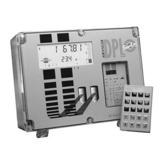
- Page 1 Instruction Manual September 2005 airanger DPL PLUS...
- Page 2 The user is responsible for all changes and repairs made to the device by the user or the user’s agent. • All new components are to be provided by Siemens Milltronics Process Instruments Inc. • Restrict repair to faulty components only.
-
Page 3: Table Of Contents
Table of Contents Introduction ..............................1 AiRanger DPL Plus ..........................1 AiRanger DPL Plus Features ........................3 Programmable Features ......................4 The Manual ...............................4 Specifications ...............................5 Electronics ..............................5 Programmer ..............................6 Transducer ..............................7 Options ...............................7 Cable ................................7 Safety marking symbols ......................8 Installation ..............................9 AiRanger DPL Plus ..........................9 Location ............................9... - Page 4 Operation ...............................23 Display in RUN Mode ...........................23 Keypad ..............................24 System Performance Evaluation .......................25 Performance Test Results ........................26 Parameter Reference ..........................27 Helpful Hints ..........................27 Parameter Reset Features ........................28 Programming Security .........................28 Quick Start (P001 to P007) ........................29 Application Parameters ........................33 Volume (P050 to P055) .........................33 Display and Reading (P060 to P062) ....................36 Failsafe (P070 to P072) ........................38 Relays (P100 to P119) ...........................40...
- Page 5 Echo Processing Displays (Scope Displays, P810) .............93 Dolphin Plus Display ........................93 Distance Calculation ..........................93 Sound Velocity ............................93 Scanning ..............................94 Volume Calculation ..........................94 Universal, Linear (P050 = 9) .......................95 Universal, Curved (P050 = 10) ....................95 Maximum Process Speed ........................95 Application Examples ...........................96 Example 1 - Level Measurement .....................97 Material Volume ..........................99 Example 2 - Space Measurement ...................99...
-
Page 7: Introduction
The transducer converts the electronic pulses to ultrasonic pulses which are emitted from the transducer face in a narrow beam. The AiRanger DPL Plus measures the time from the pulse emission, to reception of the reflection (echo) from the material. - Page 8 ® With the addition of a Siemens Milltronics Smartlinx protocol specific plug-in communications module, the AiRanger DPL Plus is compatible with popular industrial control system standards. Supported protocol include PROFIBUS DP , Allen-Bradley® Remote I/O, Modbus® RTU, and DeviceNet Programming can be done locally using the portable programmer keypad, or remotely through optional Dolphin Plus software or SmartLinx.
-
Page 9: Airanger Dpl Plus Features
The AiRanger DPL Plus is typically used to monitor material level in open or closed vessels but can be used in almost any process which requires a distance measurement (within the system range). Refer to Technical Reference Application Examples on page 96 for detailed descriptions of some configuration examples to which the AiRanger DPL Plus may be applied. -
Page 10: Programmable Features
4 range selections: 0-20, 4-20, 20-0, or 20-4 mA with an adjustable range and over-range limits The Manual The manual is designed to help you get the most out of your AiRanger DPL Plus, and it provides information on the following: •... -
Page 11: Specifications
(Type 4X / NEMA 4X / IP65 enclosure) • installation category • pollution degree: Scan Points • 2 points per AiRanger DPL Plus max. • frequency independent Range • Level Measurement: 0.3 m (1 ft) to 60 m (200 ft) max. -
Page 12: Programmer
• 67 mm W x 100 mm H x 25 mm D (2.6" W x 4" H x 1" D) • ABS plastic Weight • 150 g (0.3 lb) The use of approved watertight hubs/glands is required for Type 4X / NEMA 4X, IP65 on watertight applications. Page 6 AiRanger DPL Plus – INSTRUCTION MANUAL 7ML19981BD02... -
Page 13: Transducer
• No shielded cable necessary • maximum length 3 m RS-232 Link • Belden 8770, 3 conductor/shielded, 18 AWG (0.75 mm ) or equivalent • maximum separation 15 m (50 ft) RS-485 Link 7ML19981BD02 AiRanger DPL Plus – INSTRUCTION MANUAL Page 7... -
Page 14: Safety Marking Symbols
Safety marking symbols In manual On Product Description (Label on product: yellow background.) Caution: refer to accompanying documents (manual) for details. Alternating Current Direct Current Earth (ground) Terminal Protective Conductor Terminal Page 8 AiRanger DPL Plus – INSTRUCTION MANUAL 7ML19981BD02... -
Page 15: Installation
The following procedure applies to all AiRanger DPL Plus level monitor installations. See Application Examples on page 96 for additional installation requirements. Also, refer to the instruction manuals of all other equipment connected to the AiRanger DPL Plus for additional installation instructions. -
Page 16: Mounting
Mounting Inspect all cartons and packaging for possible damage during shipment, before removing the AiRanger DPL Plus and associated equipment. Loosen the 6 enclosure lid (captivated) screws and swing the lid open. Remove the 4 Board B mounting screws (outer corners) and remove the circuit board assembly. -
Page 17: Interconnection
Interconnection Before interconnecting system components to the AiRanger DPL Plus terminals, verify all components have been installed in accordance with the associated product instruction manuals. Connect all associated equipment cable shields to the AiRanger DPL Plus shield connections. To avoid differential ground potentials, do not connect cable shields to ground (earth) elsewhere. - Page 18 Hazardous voltage present on transducer terminals during operation • Relay contact terminals are for use with equipment having no accessible live parts and wiring having insulation suitable for at least 250V. Page 12 AiRanger DPL Plus – INSTRUCTION MANUAL 7ML19981BD02...
-
Page 19: Optional Smartlinx Module
Note: Refer to the SmartLinx module documentation for any required hardware settings prior to replacing the LCD card or closing the AiRanger DPL Plus lid. Wire in the SmartLinx card according to SmartLinx Manual. Replace the LCD card and secure in place using the screws removed in Step 1. -
Page 20: System Diagram
• Transducer cables must be run in a grounded metal conduit separate from other wiring (except TS-3 temperature sensor wiring, if applicable). • Hazardous voltage present on transducer terminals during operation. Page 14 AiRanger DPL Plus – INSTRUCTION MANUAL 7ML19981BD02... -
Page 21: Temperature Sensor
Note: relays are shown in de-energized n.o. n.c. state. to customer’s equipment See Specifications for ratings. mA Outputs OUTPUTS 0/4-20mA isolated output to Ω 7ML19981BD02 AiRanger DPL Plus – INSTRUCTION MANUAL Page 15... -
Page 22: Communication
Refer to the appropriate SmartLinx manual for installation and wiring. Level System Synchronization Avoid mounting the AiRanger DPL Plus near another ultrasonic level monitor. Likewise, when more than one monitor is installed within a single plant/facility, ensure the transducer cables of each system are run in separate grounded metal conduits. If this system separation is impractical, or if measurement difficulties are encountered, system synchronization may be required. -
Page 23: Power
• Never operate the AiRanger DPL Plus with the enclosure lid open, or with the ground (earth) wire disconnected. • Ensure that any associated alarm or control equipment is disconnected until satisfactory operation is verified. -
Page 24: Programmer
The hand programmer fits into the docking bay and is kept there with a magnet. Use the hand programmer to change individual parameters Communications Access Communications link is through the internal RJ-11 port RJ-11 port. RJ-11 cable Page 18 AiRanger DPL Plus – INSTRUCTION MANUAL 7ML19981BD02... -
Page 25: Programming
Number, or TS-3 Number as identified by the Index Type indicators. Parameter Numbers have a preset Parameter Value for each Index Number. Program the AiRanger DPL Plus to obtain the desired RUN mode operation. Display In PROGRAM mode, the Index Type, Index Number, Parameter Number, and Parameter Value (as well as a variety of other programming information) may be viewed. -
Page 26: Keypad
Keypad In PROGRAM mode, use the AiRanger DPL Plus programmer keys to perform the identified functions. numeric key values function keys Description DISPLAY: shift access to Index, Parameter Number, or Parameter Value display. NUMBERS: enter the numeric value into the accessed display. -
Page 27: Program Mode Entry
Relay status and mA output values are held at last known values (unless affected by a parameter alteration or transducer firing) until RUN mode is re- entered. RUN mode is automatically re-entered if the AiRanger DPL Plus is left unattended in PROGRAM mode for an extended period. Changing Parameters Enter the new value, and press ENTER . -
Page 28: Parameter Reset Features
To reset all parameters to preset values, use Master Reset (P999). Note: Perform a Master Reset (P999) if the AiRanger DPL Plus was bench tested using arbitrary Parameter Values before system installation, following an EPROM replacement, or whenever complete reprogramming is required. -
Page 29: Operation
Operation In RUN mode, the AiRanger DPL Plus detects material levels and provides control functions. The AiRanger DPL Plus automatically starts in RUN mode when power is applied. Display in RUN Mode In the RUN mode, the following values and indicators are observed. Many indicators are specific to certain operating conditions and so not all indicators are not displayed at any given time. -
Page 30: Keypad
PAUSE DISPLAY TOGGLE: stops/starts the point number auto display scroll. NEXT POINT: selects the next point number(when auto display scroll is stopped). PREVIOUS POINT: selects the previous point number (when auto display scroll is stopped). Page 24 AiRanger DPL Plus – INSTRUCTION MANUAL 7ML19981BD02... -
Page 31: System Performance Evaluation
(Auxiliary Reading) is reset to 100 and begins to fall toward 0 until the next valid measurement is made. If the Failsafe Time Left reaches 0, the AiRanger DPL Plus flashes LOE in the Reading display. All associated data is supplied to the Peripheral Communications terminals (27 and 28). -
Page 32: Performance Test Results
Performance Test Results Monitor system performance carefully, under all anticipated operating conditions. If the AiRanger DPL Plus performs exactly as required, copy all Parameter Value alterations to the Programming Charts in the back of this instruction manual. (Altered Parameter Values may be scroll accessed). No further action is required. -
Page 33: Parameter Reference
The AiRanger DPL Plus is configured through its parameters, and the application determines the parameter values which are entered into the unit. Please check your value entries carefully before operating the AiRanger DPL Plus to ensure optimum performance. Helpful Hints Please note the following: •... -
Page 34: Parameter Reset Features
Master Reset (P999) on page 91. Note: Perform a Master Reset (P999) if the AiRanger DPL Plus was bench tested using arbitrary Parameter Values before system installation, following an EPROM replacement, or whenever complete reprogramming is required. -
Page 35: Quick Start (P001 To P007)
For DPD and DPA Programming To set an AiRanger DPL Plus for DPA or DPD functions, Point 3 must be set to either 4 or 5 (as required). Points 1 and 2 cannot be set to 4 or 5, but these points are used to calculate the value in point 3. - Page 36 Transducer Scanning (P726 to P729) • P905 Transmit Pulse Use a setting just fast enough to keep up with your process. Slower settings provide higher accuracy. Faster settings allow for more level fluctuations. Page 30 AiRanger DPL Plus – INSTRUCTION MANUAL 7ML19981BD02...
- Page 37 P004 Transducer Specifies the Siemens Milltronics transducer connected to the unit. Primary Index Transducer No transducer attached ST-25 ST-50 ST-100 LR-21 LR-13 XCT-8 XPS-10 Values XCT-12 XPS-15 XPS-30 XPS-40 XLT-30 XLT-60 XLS-30 XLS-60 XRS-5 • P842 Short Shot Frequency •...
- Page 38 Enter a lower value if desired. If the automatic setting is not high enough, mount the transducer higher (see Installation/Transducer Mounting on page 10) and enter the new Empty (P006) distance. Page 32 AiRanger DPL Plus – INSTRUCTION MANUAL 7ML19981BD02...
-
Page 39: Application Parameters
Application Parameters Volume (P050 to P055) Use these parameters to enable the AiRanger DPL Plus to show readings based on vessel volume (rather than level). P050 Tank Shape Enter the Tank Shape value matching the monitored vessel or wet well. - Page 40 Note: Make sure selected chosen units allow LCD volume display. Examples: If max. volume = 3650 m , enter 3650 If max. volume = 267500 gallons, enter 267.5 (thousands of gallons) Page 34 AiRanger DPL Plus – INSTRUCTION MANUAL 7ML19981BD02...
- Page 41 Secondary Index Breakpoint Values Range: 0.0 to 9999 Related • P055 Volume Breakpoints Enter the following: • up to 32 level breakpoints (where volume is known) if P050 = 9 or 10 7ML19981BD02 AiRanger DPL Plus – INSTRUCTION MANUAL Page 35...
-
Page 42: Display And Reading (P060 To P062)
Ensure that each volume corresponds to the same index for P054. Press ENTER P055 Volume Breakpoints and Characterization (Universal Volume Calculation) Each segment defined by the level breakpoints (P055) requires a volume so that the AiRanger DPL Plus can make the level-to-volume calculations. Primary Index Transducer Secondary Index Breakpoint Values Range: 0.0 to 9999... - Page 43 To calculate true volumes see Volume (P050 to P055). • Avoid entering a value that, when multiplied by the maximum current Reading, exceeds the display capabilities. If value exceeds four digits, EEEE is shown. 7ML19981BD02 AiRanger DPL Plus – INSTRUCTION MANUAL Page 37...
-
Page 44: Failsafe (P070 To P072)
Failsafe (P070 to P072) As preset, in the event of a measurement or technical difficulty, the AiRanger DPL Plus holds the Reading, Bar Graph, mA outputs, and relays at their last known values. To operate process control equipment under these conditions, alter the following parameters as required. - Page 45 When a valid measurement is made before the timer expires, the AiRanger DPL Plus advances to the new material level (if changed) as normal (per Measurement Response, P003) and the timer resets. If the timer expires (before a valid measurement is made), the AiRanger DPL Plus advances to the Failsafe Material Level (P071) as restricted by Failsafe Advance (P072).
-
Page 46: Relays (P100 To P119)
Control relays have P129 = dE and so de-energize the relay when the unit enters Failsafe mode regardless of the Failsafe Material Level. P072 Failsafe Level Advance Sets the speed the AiRanger DPL Plus advances to and returns from the Failsafe Material Level. Primary Index... - Page 47 % symbol. Control functions allow each relay to be configured independently to take advantage of the AiRanger DPL Plus’s advanced features and flexibility. Start with a preset application and then change the required parameters to make the task more efficient.
- Page 48 Enter the High High Alarm material level for the index displayed, (Relay Set Up 2 or 4 only). Primary Index Transducer Range: -999 to 9999 Values Preset 90.00% of Span or equivalent units Page 42 AiRanger DPL Plus – INSTRUCTION MANUAL 7ML19981BD02...
-
Page 49: Custom Relays (P110 To P113)
If a relay is allocated to more than one Point, when any Point (in the allocation range) is in alarm, the relay de-energizes. If Point 3 is set for Difference or Average Operation (P001=4 or 5), one or more AiRanger DPL Plus relays may be allocated to Point 3. Note: When Relay Allocation is altered, affected alarm (P101 to P104) parameters display ch (changed), when accessed. - Page 50 P111 Relay Control Function Sets the control algorithm used to trip the relay. When accessed, the Parameter Type display changes to the Relay symbol and the Index display changes to the Relay Number (corresponding to the AiRanger DPL Plus terminals). Primary Index...
-
Page 51: Independent Relay Setpoints
Celsius (°C). Rate alarms are entered in Units / minute or percent of Span per minute. A positive value is entered for a filling rate alarm; negative for emptying. 7ML19981BD02 AiRanger DPL Plus – INSTRUCTION MANUAL Page 45... - Page 52 Stop pump up on level at 80% * Values shown are for illustration purposes only. Enter values which apply to your particular installation. L 2% factory set deadband, adjustable via P116 Page 46 AiRanger DPL Plus – INSTRUCTION MANUAL 7ML19981BD02...
- Page 53 The distance above and below the bound alarm setpoints. Primary Index Relay Range: 0.000 to 9999 Values Preset: 2% of span • P111 Relay Control Function Related • P112 Relay ON Setpoint • P113 Relay OFF Setpoint 7ML19981BD02 AiRanger DPL Plus – INSTRUCTION MANUAL Page 47...
-
Page 54: Independent Relay Failsafe (P129)
50 – all pump controls To select an independent Relay Failsafe value: Press MODE to display the Auxiliary Function symbol. Press ARROWS to scroll through the failsafe options. Select option and press ENTER Page 48 AiRanger DPL Plus – INSTRUCTION MANUAL 7ML19981BD02... -
Page 55: Ma Output (P200 To P219)
Output (P200 to P219) When an mA Output Parameter is accessed, the mA symbol is displayed in the Index Type field and the mA output number (corresponding to the AiRanger DPL Plus terminals) is displayed in the Index field. -
Page 56: Independent Ma Setpoints (P210 And P211)
Max Volume. Enter the volume rate in volume/min. Ensure the % symbol Volume Rate is displayed before attempting to enter a % value. mA input or Not Applicable Communications Input Page 50 AiRanger DPL Plus – INSTRUCTION MANUAL 7ML19981BD02... -
Page 57: Ma Output Limits (P212 And P213)
Sets the maximum mA output value (in mA) to be produced. Primary Index mA output Range: 0.000 to 22.00 Values Preset: 20.2 mA Related • P200 mA Output Range / P212 mA Output Min LImit 7ML19981BD02 AiRanger DPL Plus – INSTRUCTION MANUAL Page 51... -
Page 58: Ma Output Trim (P214 To P215)
Or, to produce an mA output at a specific value, enter the value required. This is used only if mA output is allocated to a transducer (P201 = 1 to 4). Page 52 AiRanger DPL Plus – INSTRUCTION MANUAL 7ML19981BD02... -
Page 59: Standard Data Logging (P300 To P321)
WARNING: These parameters are for authorized service personnel or technicians familiar with Siemens Milltronics echo processing techniques. These features can record up to ten Echo profiles, initiated manually (P330), or automatically (P331 et al) for viewing at a later time using Dolphin Plus or an oscilloscope. - Page 60 Dolphin Plus To delete a record Press CLEAR and then ENTER to delete the echo profile record in the selected address. The value returns to - - - -. Page 54 AiRanger DPL Plus – INSTRUCTION MANUAL 7ML19981BD02...
-
Page 61: Auto Record On And Off Setpoints (P334 To P337)
If ---- is displayed for either P334 or P335, Auto Profile Records are saved regardless of current level (subject to all other restrictions). Enter the level value in Units (P005) or percent of Span (P007) as referenced to Empty (P006). 7ML19981BD02 AiRanger DPL Plus – INSTRUCTION MANUAL Page 55... - Page 62 If the level changes at a rate in excess of the corresponding Filling / Emptying Indicator (P702 / P703) values, the Echo Profile is saved subject to this and other Auto Profile Record restrictions. Page 56 AiRanger DPL Plus – INSTRUCTION MANUAL 7ML19981BD02...
-
Page 63: Installation Records (P340 To P342)
• P341 RUN Time Related • P342 Start Ups P341 RUN Time View the number of days this AiRanger DPL Plus has been in operation. Primary Index Global Values Range: 0.000 to 9999 (view only) • P340 Date of Manufacture Related •... -
Page 64: Range Calibration (P650 To P654)
Repeat Step One at least five times to verify repeatability. Measure the actual reading (use tape measure). Enter the actual value. The deviation between the entered Empty (P006) value and the calibrated Empty value is stored in Offset Correction (P652). Page 58 AiRanger DPL Plus – INSTRUCTION MANUAL 7ML19981BD02... - Page 65 Values Range: -999 to 9999 Related • P650 Offset Calibration Alternatively, if the amount of Offset Correction required is known, enter the amount to be added to the Reading before display. 7ML19981BD02 AiRanger DPL Plus – INSTRUCTION MANUAL Page 59...
-
Page 66: Temperature Compensation (P660 To P664)
TS-3 Temperature Sensor Average (TS-3 and transducer) TS-3 Sensor #1 Alters • P664 Temperature • P651 Sound Velocity • P653 Velocity Related • P654 Velocity at 20°C • P661 Temp Fixed Page 60 AiRanger DPL Plus – INSTRUCTION MANUAL 7ML19981BD02... - Page 67 The AiRanger DPL Plus uses the TS-3 temperature sensor assigned to the transducer. If one is not connected, the ultrasonic/temperature transducer is used. If the transducer does not have an internal temperature sensor, the Temp Fixed (P661) value is used.
- Page 68 If Temp Source (P660) is set to any value other than Fixed Temp, the value displayed is the temperature measured. If Temp Source is set to Fixed Temp, the P661 value is displayed. Page 62 AiRanger DPL Plus – INSTRUCTION MANUAL 7ML19981BD02...
-
Page 69: Rate (P700 To P707)
Rate (P700 to P707) These parameters determine how material level changes are reported. P700 Max Fill Rate Adjusts the AiRanger DPL Plus response to increases in the actual material level (or advance to a higher Failsafe Material Level, P071). Primary Index... - Page 70 P705 Rate Update Time/ P706 Rate Update Distance Enter the time or distance interval over which the Rate Value is to be calculated before the display updates. This is automatically altered along with Maximum Process Speed (P003). Page 64 AiRanger DPL Plus – INSTRUCTION MANUAL 7ML19981BD02...
-
Page 71: Measurement Verification (P710 To P713)
P713 Echo Lock Window This value (in % of Span, P007) is automatically altered when Maximum Process Speed (P003) is altered. The higher the value entered, the greater the fluctuation stabilized. 7ML19981BD02 AiRanger DPL Plus – INSTRUCTION MANUAL Page 65... - Page 72 Echo Lock Window (P713) must meet the sampling criterion (P712). For total lock, Echo Lock Window (P713) is preset to zero 0. The AiRanger DPL Plus continuously searches for the best echo according to the algorithm chosen (P820). If the selected echo is within the window, the window is then centered about the echo.
- Page 73 When 0 is entered the window is automatically calculated after each measurement. For slower P003 Maximum Process Speed values the window is narrow, for faster P003 values the window becomes wider. 7ML19981BD02 AiRanger DPL Plus – INSTRUCTION MANUAL Page 67...
-
Page 74: Transducer Scanning (P725 To P729)
This feature may only be used to adjust the delay before the next point is scanned. Enter the amount of delay in seconds. This value is automatically altered when Maximum Process Speed (P003) is altered. Page 68 AiRanger DPL Plus – INSTRUCTION MANUAL 7ML19981BD02... -
Page 75: Display (P730 To P733)
If necessary, enter the Parameter Number to default in the Auxiliary Reading display. That value will show in the auxiliary reading area by default. Other values are available but will reset to the parameter defined here. 7ML19981BD02 AiRanger DPL Plus – INSTRUCTION MANUAL Page 69... - Page 76 / untag any accessed parameter. is displayed to indicate the parameter accessed is tagged. Note: Quick Start parameters (P001 – P007) and those changed from factory default settings cannot be untagged. Page 70 AiRanger DPL Plus – INSTRUCTION MANUAL 7ML19981BD02...
-
Page 77: Peripheral Communication Support Parameters (P740 To P749)
Displays the type of communication bus the AiRanger DPL Plus is currently set for. If there is no connection, the AiRanger DPL Plus defaults to RS-485. If a bus type other than RS-485 is connected, the AiRanger DPL Plus displays the type of bus it is, or is attempting to, communicate with. -
Page 78: Smartlinx Reserved (750 To 769)
Refer to the SmartLinx documentation to determine if any of them are used. Communications (P772) The AiRanger DPL Plus communication ports are configured by a series of parameters that are indexed by port. Communication parameters are indexed to these communication ports, unless otherwise... -
Page 79: Echo Processing (P800 To P807)
A count that increments by 1 each time a bus error (P791) is reported.. Primary Index Global Range: 0* to 9999 Values Error count; provide this number to your Siemens Milltronics repre- sentative for troubleshooting. Related • P790 Hardware Error P794 SmartLinx Module Type This parameter is used to identify the module type when SmartLinx is used. - Page 80 When a transducer with a submergence shield is submerged, the shield traps an air pocket that creates a special echo. The AiRanger DPL Plus recognizes the echo and advances the reading to the highest level and operates displays and outputs accordingly.
- Page 81 Increases AiRanger DPL Plus response when the monitored surface is close to the transducer face. Select short and long to have short and long acoustic shots fired for each measurement, regardless of the transducer to surface distance. Select short to...
-
Page 82: Advanced Echo Processing (P810 To P825)
See Noise Problems in the Troubleshooting Section on page 113. Advanced Echo Processing (P810 to P825) Note: The following parameters are for authorized Siemens Milltronics Service personnel or technicians familiar with Siemens Milltronics echo processing techniques. Anatomy of an Echo Profile The relevant parts of an echo profile are listed here. - Page 83 Alternatively, a four-digit binary value may be entered, where a 0 turns the associated signal display OFF, and a 1 turns the display ON. 1110 = PCn_ : • Echo Profile, TVT Curve, and Echo Marker displays ON • Echo Lock Window display OFF 7ML19981BD02 AiRanger DPL Plus – INSTRUCTION MANUAL Page 77...
-
Page 84: Profile Pointer (P817 To P825)
P818 Profile Pointer Distance • P819 Profile Pointer Amplitude • P820 Algorithm Related • P821 Spike Filter • P822 Narrow Echo Filter • P823 Reform Echo • P825 Echo Marker Trigger Page 78 AiRanger DPL Plus – INSTRUCTION MANUAL 7ML19981BD02... - Page 85 * bLF = short range Largest or First (general purpose) bL = short range Largest only (solids and open vessel liquids) bF = short range First only (closed vessel liquids) 7ML19981BD02 AiRanger DPL Plus – INSTRUCTION MANUAL Page 79...
- Page 86 P817 Profile Pointer Time • P818 Profile Pointer Distance • P819 Profile Pointer Amplitude Related • P820 Algorithm • P821 Spike Filter • P823 Reform Echo • P825 Echo Marker Trigger Page 80 AiRanger DPL Plus – INSTRUCTION MANUAL 7ML19981BD02...
- Page 87 Enter the value (in percent of echo height) to ensure the Echo Lock Window intersects the Echo Profile at the sharpest rising portion of the Echo Profile representing the true echo. This value is preset to 90% when P002=1 (Liquid) or 50% when P002=2 (Solid). 7ML19981BD02 AiRanger DPL Plus – INSTRUCTION MANUAL Page 81...
-
Page 88: Advanced Tvt Adjustment (P830 To P835)
Advanced TVT Adjustment (P830 to P835) Note: The following parameters are for authorized Siemens Milltronics Service personnel or technicians familiar with Siemens Milltronics echo processing techniques. Advanced TVT control applies to long shots only. P830 TVT Type Selects the TVT Curve used. - Page 89 Enter the minimum TVT Curve start point (in dB above 1 µV rms). This feature should only be used if increased Near Blanking (P800) would extend farther than desired into the measurement range. 7ML19981BD02 AiRanger DPL Plus – INSTRUCTION MANUAL Page 83...
-
Page 90: Advanced Shot Adjustment (P840 To P852)
TVT type is set to TVT Slopes (P830=6) Advanced Shot Adjustment (P840 to P852) Note: These parameters are for Siemens Milltronics service personnel only. P840 Short Shot Number The number of short shots to be fired (and results averaged) per transmit pulse. - Page 91 • P841 Long Shot Number • P842 Short Shot Frequency Related • P844 Short Shot Width • P845 Long Shot Width This feature is automatically altered when Transducer (P004) is altered. 7ML19981BD02 AiRanger DPL Plus – INSTRUCTION MANUAL Page 85...
- Page 92 P803 Shot / Pulse Mode • P840 Short Shot Number • P842 Short Shot Frequency Related • P844 Short Shot Width • P851 Short Shot Floor • P852 Short Shot Range Page 86 AiRanger DPL Plus – INSTRUCTION MANUAL 7ML19981BD02...
-
Page 93: Test (P900 To P913)
P851 Short Shot Floor This feature is automatically altered when Transducer (P004) is altered. Test (P900 to P913) Note: These parameters are for Siemens Milltronics service personnel only. P900 Software Revision Number View the EPROM Rev. #. Primary Index Global Values Range: 00.00 to 99.99 (view only) - Page 94 P901 Memory Press ENTER to activate the AiRanger DPL Plus memory test. Primary Index Global Display: view only PASS (memory test successful) Values NOVRAM EEPROM EPROM P902 Watchdog Press ENTER to put the CPU into an infinite loop to test the watchdog timer.
- Page 95 28 to 30. Press ENTER to test the AiRanger DPL Plus communications circuitry. On successful completion, PASS is displayed. Otherwise FAIL is displayed. If FAIL is displayed, repeate the test (the first test performed sets up the auto polarity function).
-
Page 96: Measurement (P920 To P927)
Press DISPLAY to end simulation. During a measurement or simulation, the AiRanger DPL Plus responds as though in the RUN mode, but the value displayed in the Reading field is affected by the Measurement Paramter selected, and the material level is displayed in the Auxiliary Reading field. - Page 97 ENTER keys. CAUTION: be careful when using this feature. All data for all points will be reset. For convenience, be sure to record the values you want to re-enter. 7ML19981BD02 AiRanger DPL Plus – INSTRUCTION MANUAL Page 91...
-
Page 98: Technical Reference
Technical Reference Transmit Pulse The AiRanger DPL Plus transmit pulse consists of one or more electrical shot pulses, which are supplied to the scanning relay. The scanning relay is activated as required, to supply the transmit pulse to the Transducer(s) connected to the AiRanger DPL Plus terminals. -
Page 99: Echo Processing Displays (Scope Displays, P810)
Reading Value, P060 to P063.) Sound Velocity The sound velocity of the transmission medium is affected by the type, temperature, and vapour pressure of the gas or vapour present. As preset, the AiRanger DPL Plus assumes 7ML19981BD02 AiRanger DPL Plus – INSTRUCTION MANUAL... -
Page 100: Scanning
Volume Calculation The AiRanger DPL Plus provides a variety of volume calculation features (P050 to P055). If the vessel to be monitored does not match any of the 8 preset Tank Shape calculations, a Universal Volume calculation may be used. Use the level/volume graph or chart provided by the vessel fabricator (or create one based on the vessel dimensions). -
Page 101: Universal, Linear (P050 = 9)
(as well as 1 breakpoint exactly at the angle) on the curve. Maximum Process Speed The Maximum Process Speed (P003) to material level changes is designed to exceed the most demanding installation requirements. 7ML19981BD02 AiRanger DPL Plus – INSTRUCTION MANUAL Page 95... -
Page 102: Application Examples
Faster independently set Max Fill/Empty Rates may be impeded by Echo Lock, Scan Delay and Shot Delay values. The Process Speed setting automatically adjusts various parameters affecting the AiRanger DPL Plus response to material level changes as in the table that follows. Values Dependent on Measurement Response Parameter... -
Page 103: Example 1 - Level Measurement
Example 1 - Level Measurement Material Level This is the most common application of the AiRanger DPL Plus level monitor. For this example we'll assume the following: • one 30 m high cement silo is to be monitored. • the maximum vessel filling rate is 0.08 m per minute. - Page 104 = 10.00 m. 12:27 am High alarm on, actual level = 21.36 m, reported level = 25.00 m. 12:47 am Infeed stopped, actual level = 22.96 m, reported level = 27.00 m. Page 98 AiRanger DPL Plus – INSTRUCTION MANUAL 7ML19981BD02...
-
Page 105: Material Volume
XCT-8 transducer is mounted in a standpipe so that the face is 18 in. above the vessel top. • a TS-3 temperature sensor is mounted in the vessel to monitor liquid temperature. 3.00ft (P007) 3.00ft (P007) 1.5ft 12.00 ft (P052) (P053) 7ML19981BD02 AiRanger DPL Plus – INSTRUCTION MANUAL Page 99... - Page 106 1 hour, on power resumption, the mA output immediately assumes the "new value". Remaining Vessel Capacity To perform a volume conversion for the preceding example, complete the following programming. Page 100 AiRanger DPL Plus – INSTRUCTION MANUAL 7ML19981BD02...
- Page 107 Now in the RUN mode, the Reading Value and mA output will represent remaining vessel capacity in cubic feet. If the mA output is still to be scaled to "space" (distance from material to Full in feet) set the mA Function (P201) to "2". 7ML19981BD02 AiRanger DPL Plus – INSTRUCTION MANUAL Page 101...
-
Page 108: Example 3 - Dual Point Differential
Transducer 2 (an XPS-10) is mounted on the plant side of the filter, 275 cm above the channel. transducer 1 transducer 2 river side plant side 275.0cm (P006) 225cm (P101) 242.0cm (P007) 12 cm (P112) 25cm (P102) Page 102 AiRanger DPL Plus – INSTRUCTION MANUAL 7ML19981BD02... - Page 109 Parameter Settings for mA Output # 1 (River level mA output set up). Number Description Instructions No entry required. (preset for 4 mA = low, 20 mA = P200 mA Range high, P001 = 1). 7ML19981BD02 AiRanger DPL Plus – INSTRUCTION MANUAL Page 103...
- Page 110 Output 1. • connect the differential level chart recorder to mA Output 2. Note that relays are de-energized in the "alarm" condition and when the AiRanger DPL Plus power is "off". Page 104 AiRanger DPL Plus – INSTRUCTION MANUAL 7ML19981BD02...
-
Page 111: Example 4 - Dual Point Average
74.00 ft (P006) 70.00 ft (P103) 68.00 ft 72.20 ft (P101) (P007) 6.00 ft 4.00 ft (P102) (P104) empty vessel target 7ML19981BD02 AiRanger DPL Plus – INSTRUCTION MANUAL Page 105... - Page 112 Relay # 2. • connect the full alarm/indicator to Relay # 3. • connect the empty alarm/indicator to Relay # 4. (Note that relays are de-energized in "power off" and "alarm" conditions). Page 106 AiRanger DPL Plus – INSTRUCTION MANUAL 7ML19981BD02...
-
Page 113: Example 5 - Tripper Measurement
When XLS (or XLT) series transducers are mounted horizontally, install a support plate under the transducers to prevent possible mounting / conduit connection damage. This is the only AiRanger DPL Plus operation where the transducers must be the same type. 325 ft... -
Page 114: Tripper Switch Setting
(e.g. Siemens Milltronics AiRanger XPL Plus). Application Assistance The preceding examples describe only a few ways in which the AiRanger DPL Plus can be applied to process measurement requirements. The AiRanger DPL Plus can be used to monitor almost any process (within the temperature, measurement range, and chemical immunity capabilities of the system) where a distance measurement or determination of presence vs. -
Page 115: Communication Support
If you encounter a difficulty applying the AiRanger DPL Plus to a process measurement requirement, please contact Siemens Milltronics or your local distributor. -
Page 116: Mt-00 Measurement Message
1 character, $0 to $F (convert to binary, e.g. scan point is not in rate or band alarm) # # # # 1 = rate alarm 2 1 = rate alarm 1 1 = band alarm 1 1 = band alarm 2 Page 110 AiRanger DPL Plus – INSTRUCTION MANUAL 7ML19981BD02... -
Page 117: Mt-01 Hold Message
Field Name Definition Start Of Message STX ($02) 2 characters, 01 (indicates the AiRanger DPL Plus was removed from the Message Type RUN mode) End Of Message CR ($0D) MT-03 Point Not Scanned start of message... -
Page 118: Maintenance
Maintenance The AiRanger DPL Plus should require no maintenance or cleaning, though good housekeeping practices in and around the area of the enclosure are recommended. Wipe out the area of the enclosure lid docking bay recess with a clean dry cloth (if necessary) before installing the programmer. -
Page 119: Troubleshooting Guide
Reading is erratic, with True echo too weak or Relocate and/or re-aim transducer at little or no relation to wrong echo being pro- material level or object material level. cessed. Proceed to Measurement Difficulties. 7ML19981BD02 AiRanger DPL Plus – INSTRUCTION MANUAL Page 113... -
Page 120: Measurement Difficulties
If a measurement difficulty occurs for greater than the Failsafe Timer (P070) setting, LOE is flashed alternately with the Reading display. Under certain conditions, a measurement difficulty may cause the AiRanger DPL Plus to lock on to a false echo and report a fixed or wrong reading. -
Page 121: Fixed Reading
Sometimes, material simply cannot be detected during vessel filling. In these cases, set up failsafe operation so the AiRanger DPL Plus anticipates the rate of material level increase and adjusts the reported Reading accordingly. This operation is reliable, as long as when the dust (or foam) settles a valid echo can be received. -
Page 122: Wrong Reading
AiRanger DPL Plus shield terminals and not to ground elsewhere. If the AiRanger DPL Plus is mounted in close proximity to (or transducer cables run near those of) another ultrasonic level monitor, see Level System Sync (P726). - Page 123 Increase the Confidence Threshold (small amounts at a time) while observing the results. If performance is not improved return the Confidence Threshold to the preset value. Connect an oscilloscope to the AiRanger DPL Plus, (see Enhancement Parameters Scope Displays, P810). While monitoring the Echo Marker, select the Algorithm (P820) best suited to the material/conditions.
-
Page 124: Programming Charts
P072 Failsafe Level Advance Relays P100 Relay Set Up (G) P101 Hi Alarm P102 Lo Alarm P103 Hi Hi Alarm P104 Lo Lo Alarm P110 Relay Allocation P111 Relay Function P112 Relay A Setpoint Page 118 AiRanger DPL Plus – INSTRUCTION MANUAL 7ML19981BD02... - Page 125 Installation Records P340 Date of Manufacture P341 Run Time P342 Start Ups Range Calibration P650 Offset Calibration P651 Sound Velocity Calibration P652 Offset Correction P653 Velocity P654 Velocity @ 20° C 7ML19981BD02 AiRanger DPL Plus – INSTRUCTION MANUAL Page 119...
- Page 126 P731 Auxiliary Reading Key (G) P732 Display Delay (G) P733 Scroll Access (G) Peripheral Communication Support P740 Peripheral Communications (G) P748 RS485 Termination P749 Serial Bus Type SmartLinx P772 Baud Rate Page 120 AiRanger DPL Plus – INSTRUCTION MANUAL 7ML19981BD02...
- Page 127 P833 TVT Start Min P834 TVT Start Slope P835 TVT Slope Min P840 Short Shot Number P841 Long Shot Number P842 Short Shot Frequency P843 Long Shot Frequency P844 Short Shot Width 7ML19981BD02 AiRanger DPL Plus – INSTRUCTION MANUAL Page 121...
- Page 128 Parameter Altered Values for Indices/Point Numbers Name P845 Long Shot Width P850 Short Shot Bias P851 Short Shot Floor P852 Short Shot Range Page 122 AiRanger DPL Plus – INSTRUCTION MANUAL 7ML19981BD02...
- Page 129 Siemens Milltronics Process Instruments Inc. Siemens Milltronics Process Instruments Inc. 2005 1954Technology Drive, P .O. Box 4225 Subject to change without prior notice Peterborough, ON, Canada K9J 7B1 Rev. 2.4 Tel: (705) 745-2431 Fax: (705) 741-0466 *7ml19981BD02* Email: techpubs.smpi@siemens.com...
Need help?
Do you have a question about the airanger DPL PLUS and is the answer not in the manual?
Questions and answers