Table of Contents
Advertisement
Quick Links
Advertisement
Table of Contents

Related Manuals for Siemens ARDOCELL PA 4 Series


Summary of Contents for Siemens ARDOCELL PA 4 Series
- Page 1 Digital Pyrometer Two-Colour PA 4x, 5x, 6x 7MC3040-.. 06/2018 Operating Manual...
- Page 3 Pyrometer Digital Two-Color ARDOCELL PA Ident.-Nr.: 105 3234 PA4_x_5x_6x_si_en.doc Stand: 20.06.2019 830 hm / 810 het...
- Page 4 Please note: Unless otherwise stated in this instruction manual, the instruments described herein are subject to change without prior notice, particularly modifications for the sake of technological advancement. Siemens AG Digital Factory Customer Services DF&PD DF CS SD OP ITM...
-
Page 5: Table Of Contents
Operating manual PA Contents Product Numbers ARDOCELL PA ..........1 Miscellaneous ................6 Information about this manual ............6 Explanation of symbols ............... 6 Liability and Warranty ................. 6 Copyright .................... 7 Safety ..................7 Intended use ..................7 User’s responsibility ................8 Safety requirements ................ - Page 6 Operating manual PA Operation of the pyrometer via terminal program ....50 13.1 Serial Data Transmission of Temperature Data ........ 51 13.2 Terminal connection via USB ............52 13.3 Terminal connection via RS485 ............53 User-defined calibration / scaling of the current output..55 14.1 Calibration/scaling via CellaView ............
- Page 7 Operating manual PA 32.5 Cable VK 02/A ................109 32.6 Cable VK 02/F ................110 Mounting combinations ............111 33.1 Mounting combination PA 20-007 ........... 111 33.2 Mounting combination PA 20-010 ........... 112 Glossary .................. 113 Shipping, Packaging and Disposal ........114 35.1 Inspecting your shipment ..............
- Page 8 Operating manual PA...
-
Page 9: Product Numbers Ardocell Pa
Operating manual PA 1 Product Numbers ARDOCELL PA Pyrometer Temperarute range Product number ARDOCELL PA 40 AF 20 MB: 500-1400 °C, D=55:1 (F50-lens) 7MC 3040-1CA40 ARDOCELL PA 40 AF 20/L MB: 500-1400 °C, D=55:1 (F50-lens) 7MC 3040-2CA40 ARDOCELL PA 40 AF 20/C MB: 500-1400 °C, D=55:1 (F50-lens) 7MC 3040-3CA40 ARDOCELL PA 40 AF 1... - Page 10 Operating manual PA Pyrometer Temperarute range Product number ARDOCELL PA 40 AF 11 MB: 750-2400 °C, D=35:1 (Wide-angle lens) 7MC 3040-1BB40 ARDOCELL PA 40 AF 11/L MB: 750-2400 °C, D=35:1 (Wide-angle lens) 7MC 3040-2BB40 ARDOCELL PA 40 AF 22 MB: 750-2400 °C, D=370:1 (Telephoto lens) 7MC 3040-1CC40 ARDOCELL PA 40 AF 22/L MB: 750-2400 °C, D=370:1 (Telephoto lens)
- Page 11 Operating manual PA Pyrometer Temperarute range Product number ARDOCELL PA 43 AF 20 MB: 600-1400 °C, D =150:1, D =30:1 7MC 3040-1CA43 (F50 lens) ARDOCELL PA 43 AF 20/L MB: 600-1400 °C, D =150:1, D =30:1 7MC 3040-2CA43 (F50 lens) ARDOCELL PA 43 AF 20/C MB: 600-1400 °C, D =150:1, D...
- Page 12 Operating manual PA Pyrometer Temperarute range Product number ARDOCELL PA 43 AF 6/L MB: 750-2400 °C, D =580:1, D =85:1 7MC 3040-2AG43 (Telephoto lens) ARDOCELL PA 43 AF 6/C MB: 750-2400 °C, D =580:1, D =85:1 7MC 3040-3AG43 (Telephoto lens) ARDOCELL PA 43 AF 11 MB: 750-2400 °C, D =85:1, D...
- Page 13 Operating manual PA Pyrometer Temperarute range Product number ARDOCELL PA 43 AF 23/L MB: 850-3000 °C, D =730:1, D =105:1 7MC3040-2CD43 (Telephoto lens) ARDOCELL PA 43 AF 23/C MB: 850-3000 °C, D =730:1, D =105:1 7MC3040-3CD43 (Telephoto lens) ARDOCELL PA 47 AF 1 MB: 700-1700 °C, D=80:1 (Standard-Lens) 7MC 3040-1AB47 ARDOCELL PA 47 AF 1/C...
-
Page 14: Miscellaneous
Operating manual PA 2 Miscellaneous Information about this manual The Operating Manual shall enable the user to properly install the pyrometer and those accessories which are necessary. Before starting installation, be sure to read and understand this entire manual, in particular the chapter on safety! The instructions contained in this manual, especially those concerning safety, as well as site-specific regulations governing UV radiation must be complied with at all times! Explanation of symbols... -
Page 15: Copyright
Operating manual PA Copyright This Operating Manual should be treated as confidential. It is solely in- tended for use by persons involved with the instrument. This manual may not be made available to a third party without prior Manufacturer’s con- sent. -
Page 16: User's Responsibility
Operating manual PA User’s responsibility The pyrometer may only be used when it is in perfect working condition. Safety requirements The instrument works with an operating voltage of 24 VDC. The voltage re- quired for operation must be supplied by a separate power supply. This power supply unit must conform to directive DIN IEC 61010. -
Page 17: Operating Controls And Display
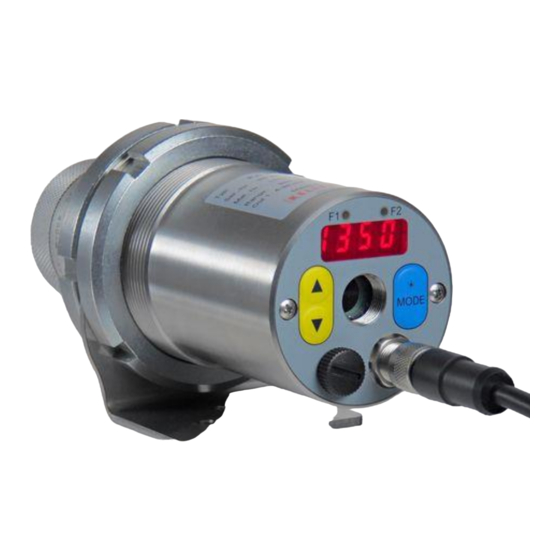
Operating manual PA The instruments have rugged stainless steel housings which make them ideal for use in hostile industrial environments. PA pyrometers are splash water proof according to IP65 (DIN 40050) All pyrometers with through-the-lens sighting feature an interchangeable, focusable lens. Through-the-lens sighting with target marker facilitates easy alignment to the target. -
Page 18: Quick Reference Guide
Operating manual PA Status LED Parameter LED Display Parameter Mode key select/change switch for laser target marker USB connection Connector socket Pyrometer rear panel 5 Quick Reference Guide PA Connector Pin Assignment Shielding 1 = white + 24 V DC 2 = brown Digital in- / output 1 3 = green... -
Page 19: Power Requirement 24 V Dc
Operating manual PA CAUTION! The pyrometer housing is connected to the signal ground via a F/50V capacitor. Isolate any unused wires in order to avoid the display of erroneous data. Power Requirement 24 V DC The instrument works with an operating voltage of 24 V DC. The voltage required for operation must be supplied by a separate power supply. -
Page 20: Switching Output
Operating manual PA yellow green VK 02/A Load maximal 500 Ω For all pyrometers of the PA Series the current outputs are short-circuit- proof and share one ground connection via pin 8 of the connector. Each current output can be individually scaled and can be set either at the dis- play or via interface. -
Page 21: Getting Started
Operating manual PA white +24 V + 24 V = 30 mA 24 V DC brown 51 KΩ relay bulb brown Digital input 1 blue Digital input 2 Ground VK 02/A See Chapter 8 for more information on configuration. 6 Getting Started General installation tips Install the pyrometer in a location where it will not be unnecessarily ex- posed to smoke, ambient heat or water vapour. -
Page 22: Pyrometers With Laser Sighting
Operating manual PA When aiming the pyrometer with through-the-lens sighting to a target, both the targeted object and the target marker (distinctly marked circled spot in the viewfinder) must appear in sharp focus simultaneously. The measured object must completely fill the target circle in the viewfinder. A variable polarising filter is available to provide eye protection. -
Page 23: Safety Instructions And Precautions
Operating manual PA Safety instructions and precautions The user must be familiar with following safety instructions. Laser Radiation Hazard Laser radiation can be harmful to eye! The PA pyrometer operates with a class 2 red light laser. Direct pro- longed viewing of a laser beam can injure the retina. Therefore, the fol- lowing safety precautions must be strictly observed, otherwise the laser may not be operated! ... -
Page 24: Pyrometer With Camera
Operating manual PA Fig. 6.2 Laser warning label affixed to the pyrometer Laser warning label must be visible! If the pyrometer is installed within a machine or equipment in such a way that the instrument’s warning label is visibly blocked, additional laser warning labels (not included in scope of delivery) must be affixed to the equipment or accessory in immediate vicinity to the laser beam emission path opening. -
Page 25: Setting Emissivity (Spectral Mode)
Operating manual PA Use ▲▼ to select the configuration layer for the parameter you wish to set. Press MODE to confirm. Press ▲▼ to select the particular pa- rameter. Press MODE to confirm. Press ▲▼ to adjust the parameter val- Press MODE again to end. -
Page 26: Setting The Emissivity Ratio (Two-Colour/Ratio Mode)
Operating manual PA reading, it is imperative that the pyrometer be adjusted for this emissivity prior to measurement. C002/C003 . Set the emissivity correction at configuration layer the Emissivity Coefficient Table in Chapter 12 to select the proper emis- sivity factor for your application. We recommend that you first perform a comparison temperature measurement with another device to determine the correct emissivity factor for the task. -
Page 27: Output Current Range
Operating manual PA When using protective windows, the transmission of the window must be adjusted for the spectral channel. The value to be set can be found in the specification of the window. Code page C003 parameter tAU.2 CAUTION! It is strongly recommended to use only approved protective windows specified by the manufacturer, which remain neutral regarding the wavelengths. -
Page 28: How The Pyrometer Functions
Operating manual PA 7 How the pyrometer functions Internal signal processing Lambda 1 peak value Sensor Segmented Filter Calculate temp. of Lambda 1 (λ Linearsation target object Lambda 2 (λ Lambda 2 PreMax (λ PreMax PreMax (λ PreMax Quotient peak value Calculate temp. -
Page 29: Configuration And Setup
Operating manual PA 8 Configuration and Setup Signal Conditioning Emissivity and Transmittance (Spectral mode) Besides the emissivity correction (mentioned in Chapter 5.6), a pyrome- ter must be adjusted for the transmission properties of any supplemen- tary lens and/or protective window screwed onto the pyrometer. Set the pyrometer for the specific transmission factor (a percentage value) which is indicated either in the products’s data sheet or on the lens itself. - Page 30 Operating manual PA Target object = 900 °C Emissivity e < 1 Reflection s > 0 Furnace radiation T = 950 °C Back Source of extraneous radiation. Example: furnace 950 °C Dirt Alert (two-colour/ratio mode) The PA pyrometers feature an integrated contamination detection func- tion.
- Page 31 Operating manual PA dirty quartz window dirt Temperature offset using linear interpolation Temperature before offset When necessary, PA pyrometer allows you to program an offset for the temperature reading reported. The offset correction can be configured individually with a minimum of 2 and a maximum of 10 interpolating points (X/Y nodes).
- Page 32 Operating manual PA Signal Smoothing Filter When the target object’s temperature is erratic, it makes sense to smooth these temperature fluctuations in order to stabilize the signal. The greater the time constant t (user definable), the lower the effect of these fluctuations on the yielded temperature reading.
- Page 33 Operating manual PA value can be shown on the rear panel display and/or transmitted to the current output for further processing. Min/Max Memory In this mode—also called peak picker—the pyrometer determines the highest or lowest temperature reading and keep the temperature read- ing.
- Page 34 Operating manual PA target object in the pyrometer’s field of view temp. reading with double max. buffer holdtime temp. measurement without double max. buffer time Automatic temperature detection (ATD) function** This function serves to automatically detect the temperature during man- ufacturing processes with discontinuous or intermittent material flow, for example molten metal casting at foundries.
- Page 35 Operating manual PA NOTE ! T. A CT Is the parameter = 0 automatically the end of the discon- T.ACT tinuous process is detected. At the parameter instead of the time “auto” is displayed. The configuration of the Normal Display Mode ( ) determines which temperature value is saved during sampling „t=0“...
- Page 36 Operating manual PA M.TR.Q for the digital outputs. Enter as the source and set the hold time to 0.5 s. A cut-off interval (time lag) begins after the sampling time has ended this cut-off interval must expire before the next measurement can start with the cycle starting conditions described above.
-
Page 37: I/O Configuration
Operating manual PA I/O Configuration Selectable current output range You will need to define the current loop scale and define a source for an analogue output signal. For a spectral pyrometer, you can select one of the following signal sources for analogue output Ao1: Quotient Lambda 1 Lambda 2... - Page 38 Operating manual PA It is also possible to configure analogue output 2 with a sub-range which covers a portion of the temperature span assigned to analogue output 1: Configuration example PA 40: Ao1: temperature reading of Lambda 1 650 - 1700 °C ≡ 4 - 20 mA Ao2: temperature reading of Lambda 1 1000 - 1500 °C ≡...
- Page 39 Operating manual PA When the digital output is to be used as a limit switch, you can configure the following parameters: Signal source Signal function and direction Limit and hysteresis at function „level“ Lower / upper limit at function = “Range” ...
- Page 40 Operating manual PA Function „Level“ Temperature [°] Switching thresh- old = “level” Hysteresis Digital output [V] 24 V Switch signal with hold time = 0 and delay time = 0 s Delay time Delay time Digital output [V] Hold time Hold time 24 V Switch signal with...
- Page 41 Operating manual PA Function “Range” Temperature [°C] Switching threshold = „Range“ Digital output [V] 24 V Switch signal with hold time = 0 and delay time = 0 s Delay time Delay time Digital output [V] Hold time Hold time 24 V Switch signal with hold time and delay...
-
Page 42: Digital Inputs
Operating manual PA Digital inputs If you want to use the digital output as an input, you must first manually deactivate the digital output and configure the following parameters: Select a current output range (either 0 – 20 mA or 4 – 20 mA) for Ao1/Ao2 ... -
Page 43: General Functions (Configuration Layer C011)
Operating manual PA Analogue input to control emissivity ratio (two-colour/ratio mode) Sometimes particular process conditions will require that the ratio of the two emissivies be changed from a remote source such as by external control. This can be achieved using the analogue input. First, manually C010 deactivate the current output 2. -
Page 44: Simulate Current Signals For Analogue Output Ao1 And Ao2
Operating manual PA Video camera settings Pyrometer models with an integrated video camera feature the following operating modes. Target Brightness Control (TBC) settings Exposure control only applies to the measurement area. ( C.TBC Exposure control applies to the entire field of view. ( C.TBC = off) As a standard, the target brightness control feature works in the target... -
Page 45: Setting Parameters At The Device
Operating manual PA ter rear panel to simulate a temperature reading, which is applied as an output current signal scaled to the selected current range. The appropri- C100 ate parameter can be accessed via configuration layer . If the py- rometer is set up correctly, the downstream controller should indicate the values you have entered (only within the scaled range). - Page 46 Operating manual PA ing invalid Emissivity Temperature offset using linear interpo- LIN.Q 2-10: number of nodes used lation (user configu- rable table) L. X1 Node x 1 - 10 Signal input (initial value) node n L. Y1 Node y 1 - 10 Signal output (resulting value) node n FIL.Q Smoothing filter...
- Page 47 Operating manual PA Temperature measurement using one-colour/spectral channel (con- C002/C003 figuration layer: Parameter Function Explanation EPS.1 Emissivity factor L1 See Chap. 8 Transmission factor TAU.1 See Chap. 8 Ambient tempera- BAC.1 See Chap. 8 ture compensation Temperature of BAC.T ambient source of radiation The reflected thermal radiation from the sur- Influence of ambient...
- Page 48 Operating manual PA show lower limit of temp. range during running measurement Mode of display** Hold previous temp. reading during run- T.HLD ning measurement A.RST Autoreset** For ATD function, see Chap. 8 CH.L.2 Set Li2 check on For ATD function, see Chap. Chap 8 T.ACT SAVE Save...
- Page 49 Operating manual PA Switch. input 2: 0V=0-20mA 24V=4- EXT.2 20mA DO1. Switching output 1 Status LED indicates ‘ready’ Lambda 1 L1.PR Lambda 1 without peak picker Lambda 2 L2.PR. Lambda 2 without peak picker Two-colour/ratio mode Two-colour/ratio mode without peak pick- Device inner temperature DO1.S Do1 select source...
- Page 50 Operating manual PA Swich direction “Level” (output activ if limit LVL. excess) Switch direction “Level” / output inverted LU.- DO2.F Do2 function Switch direction “Range” (output activ if RN6. limit excess) Switch direction “Range” / output inverted RN6- Do 2 switching Temperature limit DO2.T (only available at function “Level”)
- Page 51 Operating manual PA C011 General Functions (configuration layer: Parameter Function Explanation LED indicates 24V LED indicates digital output 1 LED indicates digital output 2 TAC1 LED indicates running measurement in LED.G Green status LED ATD function L1** TAC2 LED indicates running measurement in ATD function L2** LED indicates running measurement in TACQ...
-
Page 52: Cellaview Software
Ao2 (based on linear scale). perature* Exit menu Escape * Function only available when Current Output 2 is activated. 10 CellaView software The CellaView software displays, evaluates and stores the temperature readings of your pyrometer. Download the CellaView software here: http://www.industry.siemens.com/services/global/de/sirent/verkauf/Documents/software/cellaview.zip... -
Page 53: Installation Of The Usb Driver
Operating manual PA 11 Installation of the USB driver The ARDOCELL PA pyrometer can be addressed via a special driver. On systems with Windows 7, 8 or 10 the driver installs a virtual COM in- terface which allows access to the serial port of the pyrometer. Use the link below to download the driver www.prolific.com.tw (PL2303 Prolific Driverinstaller.zip v1.x.x) -
Page 54: How To Operate The Pyrometer With The Cellaview Software
Operating manual PA Ports (COM and LPT). You will see a listing of ports and should now be able to see which COM Port the PA USB connection assigned to. The PA USB connection will be indicated as a USB-to-Serial Comm Port. In this example, COM Port 5 has been assigned to the adapter. - Page 55 Operating manual PA Moreover, use a converter with galvanic isolation (e.g. W&T 38211) to avoid problems with ground loops. Caution ! If the supply voltage or current output are conducted via this ca- ble, then make sure to consider the voltage drop if the cable length is greater than 100 m.
-
Page 56: Cellaview Via Rs485 Bus Connection
Operating manual PA 12.3 CellaView via RS485 bus connection The RS485 two-wire bus consists of the bus cable itself with a maximum length of 1200 m. The participants are connected to this cable via a branch line with a length of 5 m max. Up to 31 pyrometers can be connected to the RS485 bus. - Page 57 Operating manual PA Caution ! All pyrometers must be connected to the same voltage supply. The maximum length of the branch lines to the pyrometer is 5 m.
-
Page 58: Termination Of Rs485 Bus
Operating manual PA Disconnect the pyrometer from any voltage source Activate or deactivate the termination of the respective partici- pant (see termination of RS485 bus) Install all required electric connections Connect the converter with the PC ... -
Page 59: Serial Data Transmission Of Temperature Data
Operating manual PA Enter press Execute the [RETURN] Main Menu or [ESC] command Select [KEY] Backspace Enter press Execute the [RETURN] Submenu 1 command or [ESC] [ESC] Select [KEY] Backspace Press [] Enter press Execute the [RETURN] Submenu 2 command or [ESC] [ESC] To set the pyrometer to the terminal mode, simultaneously hold down the... -
Page 60: Terminal Connection Via Usb
Operating manual PA Byte Negative Temperature Positive Temperature Temperature exceeds Temperature falls below measuring range measuring range Space Space Space Space Minus symbol - Space Minus symbol - Minus symbol - Digit 1000 Digit 1000 Digit 100 Digit 100 Digit 10 Digit 10 Digit 1 Digit 1... -
Page 61: Terminal Connection Via Rs485
Operating manual PA Install the pyrometer's USB driver on the PC Connect the pyrometer with a USB cable to the PC Start a standard terminal program (e.g. Windows Hyperterminal or Putty) Select the correct COM port ... - Page 62 Operating manual PA Moreover, use a converter with galvanic isolation (e.g. W&T 38211) to avoid problems with ground loops. Caution ! If the supply voltage or current output are conducted via this ca- ble, then make sure to consider the voltage drop if the cable length is greater than 100 m.
-
Page 63: User-Defined Calibration / Scaling Of The Current Output
Operating manual PA 14 User-defined calibration / scaling of the current output If necessary, the pyrometer can be adjusted with a user-defined calibra- tion function. The following drawing explains the effects for offset and factor. shall Current state Influence - factor Influence - offset Pyrometer Caution:... -
Page 64: Calibration/Scaling Via Cellaview
Operating manual PA 14.1 Calibration/scaling via CellaView To use the user-defined calibration function, activate it first in expert mode. Start CellaView Open the menu Settings Extras -> Settings Select expert mode and activate editable calibration Close the menu ... - Page 65 Operating manual PA applies to data acquisition parameters and input/output settings. Use keys "B", "C" and "D" for direct access to enable the adjustments. If you make a mistake while making the adjustments, simply enter off- set=0.0 und factor=1.0, or set User Cal. to „off“. Command "A"...
-
Page 66: Shielding And Grounding
Operating manual PA 15 Shielding and Grounding 15.1 Potential equalisation Caution: All applicable laws and codes must be complied with at all times. The pyrometer housing is connected to the shielding via the cable connector! Differences in ground potentials might cause an equalis- ing current to flow between devices through a cable shielded at both ends. - Page 67 Operating manual PA Pyrometer PA Shielded cable Shield clamp Interference voltage To avoid an equalising current, the pyrometer can be mounted elec- trically insulated. The shielding must be connected to the plant’s earthing system. Caution: If the pyrometer is installed without an insulator and without potential equalisation, the interference voltage may not ex- ceed 48 V.
-
Page 68: Connectivity Examples
Operating manual PA 16 Connectivity Examples 16.1 Connection to VK 02/A Cable Voltage supply 24 V white yellow Load 0 ... 500 Ω Current output 1 0/4 - 20 mA Flange plug (View pin side 16.2 Connection to DA 230 digital display unit white +24 V yellow... -
Page 69: Theory Of Non-Contact Temperature Measurements
Operating manual PA 17 Theory of Non-Contact Temperature Measurements All materials radiate thermal energy in all states of aggregation above absolute zero. This radiation is mainly caused by atomic or molecular oscillations. This temperature radiation is only a limited sector within the total electromagnetic radiation spectrum. -
Page 70: Measurements Of Real Radiators
Operating manual PA Most burning, annealing and hardening furnaces emit a radiation of near- ly '1' which corresponds to the conditions of a black body if the aperture through which the measurement is made is relatively small. 17.3 Measurements of Real Radiators Real radiation sources are characterized by the relation of the emitted radiation to the radiation of a black body with the same temperature. -
Page 71: Emissivity Coefficient Table Pa (Spectral Mode)
Operating manual PA 17.4 Emissivity Coefficient Table PA (Spectral mode) List of emissivity coefficients of different materials in % PA 50 2 Pyrometer PA PA 40 PA 50 1 Wavelength 0.8...1.1 m 1.1...1.7 µm "Black Body" Aluminium, polished Aluminium, blackened Asbestos cement Bronce, polished Bronze, blackened... -
Page 72: Maintenance
Operating manual PA 18 Maintenance 18.1 Cleaning the pyrometer lens A false temperature reading will be given when the lens is dirty. There- fore check the lens periodically and clean it, if necessary. Dust can be removed by simply blowing it away or by using a soft brush. A special lens cleaning cloth is ideal, but any soft, clean, lint-free cloth will be suitable. -
Page 73: Technical Data Pa 40 Af 20
Operating manual PA 19 Technical Data PA 40 AF 20 Measuring range : Mounting: Ambient operating (adjustable in partial range): External thread M 65 x 2 temperature: 500 ... 1400 °C length 40 mm 0 ... 65 °C Sensor: Connection: Excess temperature signal: Fotodiode with 8-pin connector... -
Page 74: Field Of View Diagram Pa 40 Af 20
Operating manual PA 19.1 Field of View Diagram PA 40 AF 20 ∞) Target diameter [mm] PZ 20.08 (0.3 m - D = 55 :1 Target Distance [m]... -
Page 75: Technical Data Pa 40 (650 - 1700 °C)
Operating manual PA 20 Technical Data PA 40 (650 – 1700 °C) Measuring range : Sighting device: Mounting: (adjustable in partial range): through-the-lens sighting with External thread M 65 x 2 650 ... 1700 °C target marking, laser spot light length 40 mm or integrated camera Sensor:... -
Page 76: Field Of View Diagrams Pa 40
Operating manual PA 20.1 Field of View Diagrams PA 40 ∞) Target diameter [mm] PZ 20.01 (0.4 m - D = 80 :1 Target distance [m] PZ 20.03 (0.2 – 0.4 Target diameter [mm] D = 75 :1 Target distance [mm]... - Page 77 Operating manual PA Target diameter [mm] PZ 20.06 (1.2 m - ∞) D = 120 :1 Target distance [m] Target diameter [mm] ∞) PZ 20.05 (0.2 m - D = 20 :1 Target distance [m] PA 20.06 (0.6 m - ∞) Target diameter [mm] 10.5 21.1...
-
Page 78: Technical Data Pa 40 (750 - 2400 °C)
Operating manual PA 21 Technical Data PA 40 (750 – 2400 °C) Measuring range : Sighting device: Mounting: (adjustable in partial through-the-lens sighting with External thread M 65 x 2 range): target marking, laser spot light length 40 mm 750 ... 2500 °C or integrated camera Connection: Sensor:... -
Page 79: Field Of View Diagrams Pa 40 (750 - 2400 °C)
Operating manual PA Field of View Diagrams PA 40 (750 – 2400 °C) 21.1 ∞) Target diameter [mm] PZ 20.01 (0.4 m - 13.3 D = 150 :1 4.,7 Target distance [m] PZ 20.03 (0.2 – 0.4 m) Target diameter [mm] D = 140:1 Target distance [mm] ∞) - Page 80 Operating manual PA Target diameter [mm] ∞) PZ 20.06 (1.2 m - D = 240 :1 12.5 Target distance [m] Target diameter [mm] ∞) PZ 20.05 (0.2 m - D = 35 :1 Target distance [m] PA 20.06 (0.6 m - ∞) Target diameter [mm] 10.8...
-
Page 81: Technical Data Pa 40 (850 -3000 °C)
Operating manual PA 22 Technical Data PA 40 (850 –3000 °C) Measuring range : Repeatability: Mounting: (adjustable in partial External thread M 65 x 2 range): length 40 mm Sighting device: 850 ... 3000 °C Connection: through-the-lens sighting with Sensor: target marking, laser spot light with 8-pin connector Fotodiode... -
Page 82: Field Of View Diagrams Pa 40 (850 -3000 °C)
Operating manual PA Field of View Diagrams PA 40 (850 –3000 °C) 22.1 ∞) Target diameter [mm] PZ 20.01 (0.4 m - 13.3 D = 150 :1 Target distance [m] 0.2 – 0.4 m) Target diameter [mm] PZ 20.03 ( D = 140:1 Target distance [m] ∞) - Page 83 Operating manual PA Target diameter [mm] ∞) PZ 20.05 (0.2 m - D = 35 :1 Target distance [m] Target diameter [mm] ∞) PZ 20.06 (1.2 m - D = 240 :1 12.5 Target distance [m]...
- Page 84 Operating manual PA PA 20.06 (0.6 m - ∞) Target diameter [mm] 10.8 D = 370 :1 13.5 18.9 21.6 16.2 24.3 Target distance PA 40.01 (86 – 115 mm) Target diameter [mm] 0.32 0.48 100,5 Target distance [mm]...
-
Page 85: Technical Data Pa 43 Af 20 (Mr 500 -1400 °C)
Operating manual PA 23 Technical Data PA 43 AF 20 (MR 500 -1400 °C) Measuring range : Ambient operating Connection: temperature: (adjustable in partial with 8-pin connector range): 0 ... 65 °C Protection: 500 ... 1400 °C Excess temperature signal: IP 65 according to When internal temperature ex- Sensor:... -
Page 86: Field Of View Diagram Pa 43 Af 20
Operating manual PA 23.1 Field of View Diagram PA 43 AF 20 ∞) PZ 20.08 (0.3 m - Target size [mm] Target distance [m] Horizontal: 30:1 Vertikal: 150... -
Page 87: Technical Data Pa 43 (Mr 650 - 1700 °C)
Operating manual PA 24 Technical Data PA 43 (MR 650 – 1700 °C) Measuring range : Resolution USB / RS 485: Weight: (adjustable in partial 0.1 K at terminal operation Approx. 0.9 kg range): Measuring uncertainty: Mounting: 650 ... 1700 °C 1.5 % of reading External thread M 65 x 2 (at e =1.0 and T A = 23 °C) -
Page 88: Field Of View Diagrams (Mr 650 - 1700 °C)
Operating manual PA Field of View Diagrams (MR 650 – 1700 °C) 24.1 ∞) PZ 20.01 (0.4 m - Target size [mm] Target distance [m] horizontal: 45:1 vertical: 230... - Page 89 Operating manual PA PZ 20.03 (200 – 400 mm) Target distance [m] Target size mm] horizontal: 40:1 vertical: 215:1...
- Page 90 Operating manual PA ∞ PZ 20.06 1.2 m - Target size [mm] Target distance [m] horizontal: 75:1 vertical: 375:1...
- Page 91 Operating manual PA PZ 20.05 (0.2 m - ∞) Target size [mm] Target distance [m] 1000 horizontal: 10:1 vertical: 55:1...
- Page 92 Operating manual PA ∞) PZ 20.08 (0.3 m - Target size [mm] Target distance [m] horizontal 30:1 vertical 150:1...
- Page 93 Operating manual PA ∞) PA 20.06 (0.6 m - Target size [mm] Target distance [m] 105.2 94.7 84.2 73.7 63.2 52.2 42.1 31.6 21.1 10.5 horizontal: 95:1 vertical: 500:1...
-
Page 94: Technical Data Pa 43 (Mr 750 - 3000 °C)
Operating manual PA 25 Technical Data PA 43 (MR 750 – 3000 °C) Measuring range (MR): Measuring uncertainty: Weight: 750 ... 2400 °C 1.5 % of reading Approx. 0.9 kg 850 … 3000 °C (at e =1.0 and T A = 23 °C) Mounting: Sensor: External thread M 65 x 2... -
Page 95: Field Of View Diagrams Pa 43 (Mr 750 - 3000 °C)
Operating manual PA Field of View Diagrams PA 43 (MR 750 – 3000 °C) 25.1 ∞) PZ 20.01 (0.4 m - Target size [mm] Target distance [m] horizontal: 50:1 vertical: 350:1... - Page 96 Operating manual PA PZ 20.03 (200 – 400mm). Target distance [m] Target size [mm] horizontal: 45:1 vertical: 330:1...
- Page 97 Operating manual PA ∞) PZ 20.06 (1,2 m - Target size [mm] Target distance [m] Horizontal: 85:1 Vertikal: 580:1...
- Page 98 Operating manual PA ∞) PA 20.06 (0.6 m - Target size [mm] Target distance [m] 13.7 92.3 12.3 85.7 84.2 76.2 57.1 47.6 38.1 28.6 horizontal: 105:1 vertical: 730:1...
- Page 99 Operating manual PA PZ 20.05 (0.2 m - ∞) Target size [mm] Target distance [m] horizontal: 11:1 vertical: 85:1...
- Page 100 Operating manual PA ∞) PZ 20.08 (0.3 m - Target size [mm] Target distance [m] horizontal: 34:1 vertical: 230:1...
-
Page 101: Technical Data Pa 43 Af 17
Operating manual PA Technical Data PA 43 AF 17 Measuring range (MR): Connection: Ambient operating 750 ... 2400 °C with 8-pin connector temperature: Sensor: Protection: 0 ... 65 °C Fotodiode IP 65 according to Excess temperature signal: DIN 40050 Spectral sensitivity: When internal temperature ex- (when connector is attached) 0.95/ 1.05 µm... -
Page 102: Field Of View Diagram Pa 43 Af 17
Operating manual PA 26.1 Field of View Diagram PA 43 AF 17 PA 40.01 (86 – 115 mm) [mm] Target distance Target size [mm] 0.29 1.57 0.,89 0.22... -
Page 103: Technical Data Pa 47
Operating manual PA 27 Technical Data PA 47 Measuring range : Excess temperature signal: Protection: (adjustable in partial range): When internal temperature ex- IP 65 according to 700 ... 1700 °C ceeds > 80 °C, the analogue DIN 40050 output value will be > 20.5 mA! (when connector is attached) Sensor: Storage temperature:... -
Page 104: Field Of View Diagrams Pa 47
Operating manual PA 27.1 Field of View Diagrams PA 47 PZ 20.01 (0.4 m - ∞) Target diameter [mm] D = 80 :1 Target distance [m]... -
Page 105: Technical Data Pa 50
Operating manual PA 28 Technical Data PA 50 Measuring range : Sighting device: Mounting: (adjustable in partial range): through-the-lens sighting with External thread M 65 x 2 500 ... 1400 °C target marking, laser spot light length 40 mm or integrated camera Sensor: Connection: Ambient operating... -
Page 106: Field Of View Diagrams Pa 50
Operating manual PA 28.1 Field of View Diagrams PA 50 PZ 20.03 (0.2 – 0.4 Target diameter [mm] D = 75 :1 Target distance [mm] ∞) Target diameter [mm] PZ 20.01 (0.4 m - D = 80 :1 Target distance [m]... - Page 107 Operating manual PA Target diameter [mm] ∞) PZ 20.06 (1.2 m - D = 120 :1 Target distance [m] Target diameter [mm] ∞) PZ 20.05 (0.2 m - D = 20 :1 Target distance [m]...
-
Page 108: Technical Data Pa 60
Operating manual PA 29 Technical Data PA 60 Measuring range : Ambient operating Connection: temperature: (adjustable in partial range): with 8-pin connector 300 ... 800 °C 0 ... 65 °C Protection: Sensor: Excess temperature signal: IP 65 according to Fotodiode When internal temperature ex- DIN 40050 ceeds >... -
Page 109: Field Of View Diagram Pa 60
Operating manual PA 29.1 Field of View Diagram PA 60 Target diameter [mm] ∞) PZ 20.05 (0.2 m - D = 20 :1 Target distance [m]... -
Page 110: Dimensions
Operating manual PA 30 Dimensions Messabstand... -
Page 111: Technical Data Camera
Operating manual PA 31 Technical data camera Video-System: Composite Video PAL, 1 Vpp, 75 Ohm Connection: Pyrometer -> TNC plug, monitor-> chinch or BNC (video cable VK 02/F), electrically isolated from the power supply of the pyrometer Resolution: 722 x 576 pixel ... - Page 112 Operating manual PA Optic Arera target size [m] HFOV 16.2 44.9 54.4 92.7 [mm] Standard 20.01 VFOV 12.1 33.7 40.8 69.5 [mm] HFOV 14.1 19.8 [mm] Close-up 20.03 VFOV 10.6 14.8 [mm] HFOV 32.5 56.4 86.3 [mm] Tele lens 20.06 VFOV 24.4 42.3...
-
Page 113: Accessories
Operating manual PA 32 Accessories Description Product Name Article No. Cable VK 02/A 101 3909 length 5 m, 8 x 0.25 mm², shielded Video cable VK 02/F 103 1446 Polarising filter PA 20/P 100 9974 Mounting bracket PA 11/U 100 9679 Quarz window PA 20/I 1008144... -
Page 114: Polarising Filter
Operating manual PA 32.2 Polarising filter Pyrometer PA Polarising filter PA 20/P... -
Page 115: Mounting Bracket Pa 11/U
Operating manual PA 32.3 Mounting bracket PA 11/U Pyrometer PA Mounting bracket PA 11/U... -
Page 116: Quarz-Window Pa 20/I
Operating manual PA 32.4 Quarz-window PA 20/I CAUTION ! The replacement of the protection glass can be performed only by authorized person. When removing the protective screen, always wear protective glasses and -gloves... -
Page 117: Cable Vk 02/A
Operating manual PA 32.5 Cable VK 02/A Ident. - Nr. 101 3909... -
Page 118: Cable Vk 02/F
Operating manual PA 32.6 Cable VK 02/F Ident. - Nr. 103 1446... -
Page 119: Mounting Combinations
Operating manual PA 33 Mounting combinations 33.1 Mounting combination PA 20-007... -
Page 120: Mounting Combination Pa 20-010
Operating manual PA 33.2 Mounting combination PA 20-010... -
Page 121: Glossary
Operating manual PA 34 Glossary Autoprint After connecting the power supply, the pyrometer automatically begins transmitting measurement data via the serial interface. Print cycle time The cycle time for the temperature data output via the serial interface. Distance to target size ratio Describes the ratio between the pyrometer-to-object distance and the target spot diameter. -
Page 122: Shipping, Packaging And Disposal
Should you discover a concealed loss or damage, report it to SIEMENS and to the freight carrier immediately. If the period for filing claims has expired, you will no longer be able to make any claims for compensation of damage or loss. -
Page 123: Copyright
Operating manual PA 36 Copyright Portions of avr-libc are Copyright (c) 1999-2007 Keith Gudger, Bjoern Haase, Steinar Haugen, Peter Jansen, Reinhard Jessich, Magnus Johansson, Artur Lipowski, Marek Michalkiewicz, Colin O'Flynn, Bob Paddock, Reiner Patommel, Michael Rickman, Theodore A. Roth, Juergen Schilling, Philip Soeberg, Anatoly Sokolov, Nils Kristian Strom,... -
Page 124: Default Settings
Operating manual PA 37 Default settings 37.1 Temperature measurement using two-colour/ratio mode (Configuration layer: C001) Parameter Function Default User settings EPS.Q Ratio correction 100 % Plausibility check ratio CH.R.Q mode DRC.N Soot factor n* CH.R._ Relative limit min. 10 % CH.R.~ Relative limit max. -
Page 125: Temperature Measurement Using Spectral Mode (Configuration Layer: C002, C003)
Operating manual PA 37.2 Temperature measurement using spectral mode (Configura- tion layer: C002, C003) Parameter Function Default User settings EPS.1 Emissivity factor L1 99.6% TAU.1 Transmission factor L1 100 % Ambient temperature BAC.1 compensation Temperature of BAC.T ambient source of radia- tion Influence of ambient IR BAC.%... -
Page 126: Configuration I/O (Configuration Layer: C010)
Operating manual PA C010 37.3 Configuration I/O (configuration layer: Parameter Function Default User settings AO1.S Ao1 select source Quotient Ao1 define lower limit of Measuring range AO1._ temp. span begin Ao1 define upper limit of Measuring range AO1.~ temp. span 4 –... -
Page 127: General Functions (Configuration Layer: C011)
Operating manual PA C011 37.4 General Functions (configuration layer: Parameter Funktion Default Eigene Einstel- lungen LED.G Green status LED PILO. Activate laser* TERM. Assign Interface PIL.T Laser ON-time 2 min Automatic temperature A.STR. data output Cycle for automatic 0. s temp. - Page 132 Siemens AG Digital Factory Customer Services DF&PD DF CS SD OP ITM Telefon +49 (911) 750-9600 +49 (911) 750-9609 Email: sirent.industry@siemens.com Office/Testing Warehouse/Counter service Breslauer Str. 5 Gundelfinger Str. 20 90766 Fürth 90451 Nürnberg Germany Germany Subject to change without notice...
Need help?
Do you have a question about the ARDOCELL PA 4 Series and is the answer not in the manual?
Questions and answers