
Related Manuals for Beckhoff EL922 Series


Summary of Contents for Beckhoff EL922 Series
- Page 1 Documentation EL922x Electronic overcurrent protection terminals Version: Date: 2018-11-23...
-
Page 3: Table Of Contents
Table of contents Table of contents 1 Product overview electronic overcurrent protection terminal .............. 5 2 Foreword .............................. 6 Notes on the documentation...................... 6 Safety instructions .......................... 7 Documentation issue status ...................... 8 Version identification of EtherCAT devices .................. 9 3 Product overview............................. 13 Introduction ............................ 13 Technical data .......................... 16 4 Basic function principles ........................ 20 5 Basics communication ........................... 21 EtherCAT basics.......................... 21... - Page 4 Table of contents 7.5.1 EL9221-xxxx ........................ 106 7.5.2 EL9222-xxxx ........................ 108 7.5.3 EL9227-xxxx ........................ 110 Object description and parameterization .................. 114 7.6.1 EL9221-xxxx ........................ 115 7.6.2 EL9222-xxxx ........................ 123 7.6.3 EL9227-xxxx ........................ 131 8 Diagnostics ............................ 148 Diagnostics – basic principles of diag messages ................ 148 Text ID’s EL922x ........................... 151 9 Appendix .............................. 152 EtherCAT AL Status Codes ...................... 152...
-
Page 5: Product Overview Electronic Overcurrent Protection Terminal
Product overview electronic overcurrent protection terminal Product overview electronic overcurrent protection terminal EL9221-4030 Overcurrent protection terminal [} 13], 1-channel, I 3 A, EL9221-5000 Overcurrent protection terminal [} 13], 1-channel, I adjustable up to 10 A, EL9221-5090 Overcurrent protection terminal [} 13], 1-channel, I 10 A, EL9221-6000 Overcurrent protection terminal [} 13], 1-channel, I adjustable up to 4 A,... -
Page 6: Foreword
The TwinCAT Technology is covered, including but not limited to the following patent applications and patents: EP0851348, US6167425 with corresponding applications or registrations in various other countries. ® EtherCAT is registered trademark and patented technology, licensed by Beckhoff Automation GmbH, Germany. Copyright © Beckhoff Automation GmbH & Co. KG, Germany. -
Page 7: Safety Instructions
All the components are supplied in particular hardware and software configurations appropriate for the application. Modifications to hardware or software configurations other than those described in the documentation are not permitted, and nullify the liability of Beckhoff Automation GmbH & Co. KG. Personnel qualification This description is only intended for trained specialists in control, automation and drive engineering who are familiar with the applicable national standards. -
Page 8: Documentation Issue Status
Foreword Documentation issue status Version Comment public issue - Complements, corrections 0.2 – 0.9.3 - Complements, corrections - Provisional documentation for EL922x Version: 1.0 EL922x... -
Page 9: Version Identification Of Ethercat Devices
Production lot/batch number/serial number/date code/D number The serial number for Beckhoff IO devices is usually the 8-digit number printed on the device or on a sticker. The serial number indicates the configuration in delivery state and therefore refers to a whole production batch, without distinguishing the individual modules of a batch. -
Page 10: Fig. 2 El5021 El Terminal, Standard Ip20 Io Device With Serial/ Batch Number And Revision Id (Since 2014/01)
Foreword Example with Ser. no.: 12063A02: 12 - production week 12 06 - production year 2006 3A - firmware version 3A 02 - hardware version 02 Exceptions can occur in the IP67 area, where the following syntax can be used (see respective device documentation): Syntax: D ww yy x y z u D - prefix designation... -
Page 11: Fig. 3 Ek1100 Ethercat Coupler, Standard Ip20 Io Device With Serial/ Batch Number
Foreword Fig. 3: EK1100 EtherCAT coupler, standard IP20 IO device with serial/ batch number Fig. 4: CU2016 switch with serial/ batch number Fig. 5: EL3202-0020 with serial/ batch number 26131006 and unique ID-number 204418 EL922x Version: 1.0... -
Page 12: Fig. 6 Ep1258-00001 Ip67 Ethercat Box With Batch Number/ Date Code 22090101 And Unique Se- Rial Number 158102
Foreword Fig. 6: EP1258-00001 IP67 EtherCAT Box with batch number/ date code 22090101 and unique serial number 158102 Fig. 7: EP1908-0002 IP67 EtherCAT Safety Box with batch number/ date code 071201FF and unique serial number 00346070 Fig. 8: EL2904 IP20 safety terminal with batch number/ date code 50110302 and unique serial number 00331701 Fig. 9: ELM3604-0002 terminal with unique ID number (QR code) 100001051 and serial/ batch number 44160201... -
Page 13: Product Overview
Product overview Product overview Introduction Electronic overcurrent protection terminal EL9221-xxxx | Single-channel overcurrent protection terminal with standard functionalities Fig. 10: EL9221-5000 The EL9221-xxxx electronic overcurrent protection terminal is a 24 V DC EtherCAT Terminal with electronic protection function. The single-channel EL9221-xxxx reliably switches off 24 V DC overcurrents. The nominal current can be set in 1 A steps up to 10 A, either via TwinCAT or via a mechanical pushbutton on the overcurrent protection terminal. -
Page 14: Fig. 11 El9222-5500
Product overview EL9222-xxxx | Two-channel overcurrent protection terminal with standard functionalities Fig. 11: EL9222-5500 The EL9222-xxxx electronic overcurrent protection terminal is a 24 V DC EtherCAT Terminal with electronic protection function. The 2-channel EL9222-xxxx reliably switches off 24 V DC overcurrents. The nominal current can be set in 1 A steps up to ∑... - Page 15 Product overview The EL9227-xxxx has extended functionalities, i.e. it is additionally able to handle monitoring applications, since numerous process data are available, e.g.: enabled, tripped, short circuit, overload, overvoltage, undervoltage, current level warning, cool down lock, hardware protection, switched off by pushbutton, DI, EtherCAT, load, instantaneous current, input voltage and output voltage.
-
Page 16: Technical Data
Product overview Technical data Technical data EL9221-5000 EL9221-6000 EL9221-4030 EL9221-6040 EL9221-9060 EL9221-9080 EL9221-5090 Nominal voltage 24 V (-15 %/+20 %) Nominal current max. 10 A, max. 4 A, ad- 3 A, fixed 4 A, fixed 6 A, fixed 8 A, fixed 10 A, fixed adjustable justable... - Page 17 Product overview Technical data EL9222-5500 EL9222-6600 EL9222-4433 EL9222-6644 EL9222-9664 EL9222-9482 Nominal voltage 24 V (-15 %/+20 %) Nominal current Max. Ʃ10 A max. 4 A, ad- 3 A / 3 A, 4 A / 4 A, 6 A / 4 A, 8 A / 2 A, ajustable justable...
- Page 18 Product overview Technical data EL9227-5500 EL9227-6600 EL9227-4433 EL9227-6644 EL9227-9664 EL9227-9482 Nominal voltage 24 V (-15 %/+20 %) Nominal current Max. Ʃ10 A, ad- Max. 4 A, ad- 3 A / 3 A, fixed 4 A / 4 A, fixed 6 A / 4 A, fixed 8 A / 2 A, fixed justable justable...
- Page 19 Product overview Table 1: Typical tripping times for: EL9221-5000*; EL9221-5090*; EL9222-5500*; EL9227-5500 X * I Current fast standard slow t / in ms 7,000 10,000 15,000 7,000 10,000 15,000 3,500 5,000 7,500 3,500 5,000 7,500 1,000 1,500 1,000 1,500 1,000 1,500 ≥...
-
Page 20: Basic Function Principles
Basic function principles Basic function principles The functional principle of the electronic overcurrent protection terminals is based on measurement and evaluation of the current flow. Depending on the result of the evaluation, the corresponding action is then executed. One possible action is shutdown. There are several shutdown options: once according to typical tripping times (characteristic curve), according to hardware parameters or after exceeding the limit load integral.. -
Page 21: Basics Communication
EtherCAT devices from Beckhoff. Recommended cables Suitable cables for the connection of EtherCAT devices can be found on the Beckhoff website! E-Bus supply A bus coupler can supply the EL terminals added to it with the E-bus system voltage of 5 V; a coupler is thereby loadable up to 2 A as a rule (see details in respective device documentation). -
Page 22: General Notes For Setting The Watchdog
Basics communication Fig. 13: System manager current calculation NOTE Malfunction possible! The same ground potential must be used for the E-Bus supply of all EtherCAT terminals in a terminal block! General notes for setting the watchdog ELxxxx terminals are equipped with a safety feature (watchdog) that switches off the outputs after a specifiable time e.g. -
Page 23: Fig. 14 Ethercat Tab -> Advanced Settings -> Behavior -> Watchdog
Basics communication Fig. 14: EtherCAT tab -> Advanced Settings -> Behavior -> Watchdog Notes: • the multiplier is valid for both watchdogs. • each watchdog has its own timer setting, the outcome of this in summary with the multiplier is a resulting time. -
Page 24: Ethercat State Machine
Basics communication Example "Set SM watchdog" This checkbox enables manual setting of the watchdog times. If the outputs are set and the EtherCAT communication is interrupted, the SM watchdog is triggered after the set time and the outputs are erased. This setting can be used for adapting a terminal to a slower EtherCAT master or long cycle times. -
Page 25: Fig. 15 States Of The Ethercat State Machine
Basics communication Fig. 15: States of the EtherCAT State Machine Init After switch-on the EtherCAT slave in the Init state. No mailbox or process data communication is possible. The EtherCAT master initializes sync manager channels 0 and 1 for mailbox communication. Pre-Operational (Pre-Op) During the transition between Init and Pre-Op the EtherCAT slave checks whether the mailbox was initialized correctly. -
Page 26: Coe Interface
Basics communication Boot In the Boot state the slave firmware can be updated. The Boot state can only be reached via the Init state. In the Boot state mailbox communication via the file access over EtherCAT (FoE) protocol is possible, but no other mailbox communication and no process data communication. -
Page 27: Fig. 16 "Coe Online " Tab
Data management If slave CoE parameters are modified online, Beckhoff devices store any changes in a fail-safe manner in the EEPROM, i.e. the modified CoE parameters are still available after a restart. The situation may be different with other manufacturers. -
Page 28: Fig. 17 Startup List In The Twincat System Manager
Changes in the local CoE list of the terminal are lost if the terminal is replaced. If a terminal is re- placed with a new Beckhoff terminal, it will have the default settings. It is therefore advisable to link all changes in the CoE list of an EtherCAT slave with the Startup list of the slave, which is pro- cessed whenever the EtherCAT fieldbus is started. -
Page 29: Fig. 18 Offline List
Basics communication Fig. 18: Offline list • If the slave is online ◦ The actual current slave list is read. This may take several seconds, depending on the size and cycle time. ◦ The actual identity is displayed ◦ The firmware and hardware version of the equipment according to the electronic information is displayed ◦... - Page 30 • Channel 1: parameter range 0x8010:00 ... 0x801F:255 • Channel 2: parameter range 0x8020:00 ... 0x802F:255 • ... This is generally written as 0x80n0. Detailed information on the CoE interface can be found in the EtherCAT system documentation on the Beckhoff website. Version: 1.0 EL922x...
-
Page 31: Mounting And Wiring
• Each assembly must be terminated at the right hand end with an EL9011 or EL9012 bus end cap, to en- sure the protection class and ESD protection. Fig. 20: Spring contacts of the Beckhoff I/O components Additional cover of the housing required! The terminal housings are specified for use in the IO system. -
Page 32: Installation On Mounting Rails
Mounting and wiring Installation on mounting rails WARNING Risk of electric shock and damage of device! Bring the bus terminal system into a safe, powered down state before starting installation, disassembly or wiring of the bus terminals! Assembly Fig. 21: Attaching on mounting rail The bus coupler and bus terminals are attached to commercially available 35 mm mounting rails (DIN rails according to EN 60715) by applying slight pressure: 1. -
Page 33: Fig. 22 Disassembling Of Terminal
Mounting and wiring Disassembly Fig. 22: Disassembling of terminal Each terminal is secured by a lock on the mounting rail, which must be released for disassembly: 1. Pull the terminal by its orange-colored lugs approximately 1 cm away from the mounting rail. In doing so for this terminal the mounting rail lock is released automatically and you can pull the terminal out of the bus terminal block easily without excessive force. -
Page 34: Fig. 23 Power Contact On Left Side
Mounting and wiring Fig. 23: Power contact on left side NOTE Possible damage of the device Note that, for reasons of electromagnetic compatibility, the PE contacts are capacitatively coupled to the mounting rail. This may lead to incorrect results during insulation testing or to damage on the terminal (e.g. disruptive discharge to the PE line during insulation testing of a consumer with a nominal voltage of 230 V). -
Page 35: Connection
Mounting and wiring Connection 6.3.1 Connection system WARNING Risk of electric shock and damage of device! Bring the bus terminal system into a safe, powered down state before starting installation, disassembly or wiring of the bus terminals! Overview The Bus Terminal system offers different connection options for optimum adaptation to the respective application: •... -
Page 36: Wiring
Mounting and wiring A tab for strain relief of the cable simplifies assembly in many applications and prevents tangling of individual connection wires when the connector is removed. Conductor cross sections between 0.08 mm and 2.5 mm can continue to be used with the proven spring force technology. -
Page 37: Fig. 26 High Density Terminals
Mounting and wiring Terminals for standard wiring ELxxxx/KLxxxx and for pluggable wiring ESxxxx/KSxxxx Fig. 27: Connecting a cable on a terminal point Up to eight terminal points enable the connection of solid or finely stranded cables to the Bus Terminal. The terminal points are implemented in spring force technology. -
Page 38: Prescribed Installation Position
Mounting and wiring 6.3.2.1 Wire cross-section of the load circuit NOTE Adapting the wire cross-section to the load circuit The user must ensure that the wire cross-section of the respective load circuit is adapted accordingly! Prescribed installation position NOTE Constraints regarding installation position and operating temperature range When installing the terminals ensure that an adequate spacing is maintained between other components above and below the terminal in order to guarantee adequate ventilation! Prescribed installation position... -
Page 39: Installation Instructions For Enhanced Mechanical Load Capacity
Mounting and wiring Installation instructions for enhanced mechanical load capacity WARNING Risk of injury through electric shock and damage to the device! Bring the Bus Terminal system into a safe, de-energized state before starting mounting, disassembly or wiring of the Bus Terminals! Additional checks The terminals have undergone the following additional tests: Verification... -
Page 40: Positioning Of Passive Terminals
Mounting and wiring Positioning of passive Terminals Hint for positioning of passive terminals in the bus terminal block EtherCAT Terminals (ELxxxx / ESxxxx), which do not take an active part in data transfer within the bus terminal block are so called passive terminals. The passive terminals have no current consump- tion out of the E-Bus. -
Page 41: Leds And Pin Assignment, Programming With Led Buttons
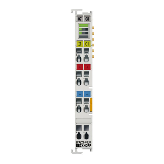
Mounting and wiring LEDs and pin assignment, programming with LED buttons 6.7.1 EL9221-xxxx LEDs and connection Fig. 31: EL9221-5000, assignment and designation of connections and LEDs Meaning of the connections Terminal point Description Name Digital input 1 Digital input for switching output 1 (negative edge;... - Page 42 Mounting and wiring Meaning of the LEDs and button LED EL9221-xxxx Color Meaning Button LED 1 This button LED 1 indicates the status of output 1 Green Output 1 switched off Output 1 switched on flashing Programming mode active: Permissible nominal current value for output 1 can be read with flashing code (1x flashing = 1 A;...
- Page 43 Mounting and wiring For operation in the respective modes, please refer to the table LED buttons Operation / Programming. Button LED Operation / Programming State Meaning Operation in operation mode Button LED 1 Press briefly Switching output 1 on and off or resetting it Long press (>3s) Activating the programming or query mode Operation in programming mode...
-
Page 44: El9222-Xxxx
Mounting and wiring 6.7.2 EL9222-xxxx LEDs and connection Fig. 32: EL9222-5500, assignment and designation of connections and LEDs Meaning of the connections Terminal point Description Name Digital input 1 Digital input for switching output 1 (negative edge; 0 V reference as supply) 24 V power supply +24 V DC input voltage (internally connected to terminal point 6) 0 V power supply... - Page 45 Mounting and wiring Meaning of the EL9222-xxxx LEDs and button LEDs Color Meaning Button Button LED 1 indicates the status of output 1. LED 1 Green Output 1 switched off Output 1 switched on flashing Programming mode active: Permissible nominal current value for output 1 can be read with flashing code (1x flashing = 1 A;...
- Page 46 Mounting and wiring The EL9222-xxxx has illuminated push-buttons! The illuminated push-buttons allow the overcurrent protection terminal to be operated, e.g. switch- ing on and off and resetting the respective output. They are also used for programming and query- ing the nominal current. There are 3 modes: operation mode, programming mode and query mode. There is a common programming mode in which the two outputs can be set simultaneously, as they are interdependent for the terminal with sum current limitation.
- Page 47 Mounting and wiring Behavior of the outputs when the settings are changed If settings are changed during operation (outputs are switched on), the outputs remain switched on. This has the advantage that the system can remain in operation and a change can be made "on- line".
-
Page 48: El9227-Xxxx
Mounting and wiring 6.7.3 EL9227-xxxx LEDs and connection Fig. 33: EL9227-5500, assignment and designation of connections and LEDs Meaning of the connections Terminal point Description Name Digital input 1 Digital input for switching output 1 (negative edge; 0 V reference as supply) 24 V power supply +24 V DC input voltage (internally connected to terminal point 6) 0 V power supply... - Page 49 Mounting and wiring Meaning of the EL9227-xxxx LEDs and button LEDs Color Meaning Button Button LED 1 indicates the status of output 1. LED 1 Green Output 1 switched off Output 1 switched on flashing Programming mode active; permissible nominal current value for output 1 can be read with flashing code (1x flashing = 1 A;...
- Page 50 Mounting and wiring The EL9227-xxxx has illuminated push-buttons! The illuminated push-buttons allow the overcurrent protection terminal to be operated, e.g. switch- ing on and off and resetting the respective output. They are also used for programming and query- ing the nominal current. There are 3 modes: operation mode, programming mode and query mode. There is a common programming mode in which the two outputs can be set simultaneously, as they are interdependent for the terminal with sum current limitation.
- Page 51 Mounting and wiring Behavior of the outputs when the settings are changed If settings are changed during operation (outputs are switched on), the outputs remain switched on. This has the advantage that the system can remain in operation and a change can be made "on- line".
-
Page 52: Sample Programming
Mounting and wiring 6.7.4 Sample programming The EL922x devices have illuminated push-buttons! The illuminated push-buttons allow the overcurrent protection terminal to be operated, e.g. switch- ing on and off and resetting the respective output. They are also used for programming and query- ing the nominal current. - Page 53 Mounting and wiring Sample programming 2 Operation Display Meaning Press button LED 1 for >3 seconds Activate programming mode Ready LED lights up orange Programming mode is active Button LED 1 flashes 6x green Output 1 is set to 6 A Button LED 2 flashes 4x green Output 2 is set to 4 A Press button LED 1 7x...
-
Page 54: Commissioning
Commissioning Commissioning The EL922x is an EtherCAT Terminal with electronic overcurrent protection function. The overcurrent protection function is available at all times, i.e. as soon as the input voltage has been applied, the overcurrent protection function is active (after a successful initialization run), regardless of whether EtherCAT is present or not. -
Page 55: Quick Start: Commissioning Of The El922X Without Ethercat
Commissioning NOTE Permanent reset, Permanent switch-on/switch-off A permanently applied reset process and continuous switching on and off of the supply voltage is not per- mitted. This could lead to destruction of the electronics. NOTE Restart delay EL9221 / EL9222 If another tripping event takes place within 15 seconds after a 10-second restart lock has elapsed, the cool- ing time is extended by an additional 10 seconds. -
Page 56: Fig. 34 Exemplary Wiring Of An El9221-5000 And El9227-5500
Commissioning Fig. 34: Exemplary wiring of an EL9221-5000 and EL9227-5500 Fig. 35: Exemplary wiring of an input voltage of the EL9221-5000 to another terminal. 3. Nominal current setting Use button LED 1 or button LED 2 to set the desired nominal current. Programming sequence: Press one of the LED buttons for ≥3 seconds. - Page 57 Commissioning nominal current for output 1. Press once = 1 A, press twice = 2 A, .., press 10 times = 10 A, press … ≥11 times = OFF; (in the 4 A variant, press ≥5 times = Off). For output 2, use button LED 2. Press one of the LED buttons for ≥3 seconds to save your entries.
-
Page 58: Commissioning And Parameterization Of The El922X With Ethercat
Commissioning Commissioning and parameterization of the EL922x with EtherCAT To commission the EL922x with EtherCAT, proceed as follows: 1. Mounting Mount the EL922x as described in the chapter Mounting and wiring [} 31] 2. Terminal wiring Power supply Connect the 24 V DC power supply to the respective terminal contacts. Supply 24 V DC to terminal contacts 2 or 6 and 0 V to terminal contacts 3 or 7. -
Page 59: Fig. 37 Exemplary Wiring Of An Input Voltage Of The El9221-5000 To Another Terminal
EtherCAT XML Device Description If the XML description of the EL922x is not available in your system you can download the latest XML file from the download area of the Beckhoff website and install it according to the installation instructions. -
Page 60: Fig. 38 Coe-8000-Settings - El9227
Commissioning Fig. 38: CoE-8000-Settings – EL9227 Fig. 39: CoE-8000-Settings - EL9222 DIG Safe State Active (index 0x80n0:01) / DIG Safe State Value (index 0x80n1:01) The setting in “DIG Safe State Active” (index 0x80n0:01) defines whether the outputs should assume a safe state in the case of a bus error. The safe state of the output in the case of a bus error is defined with “DIG Safe State Value”... - Page 61 Commissioning DIG Safe State Active DIG Safe State Value Output before bus er- Output bus error oc- Index 0x80n0:01 Index 0x80n1:01 curs TRUE TRUE FALSE TRUE TRUE TRUE TRUE FALSE FALSE FALSE TRUE FALSE FALSE FALSE / TRUE FALSE FALSE TRUE TRUE DIG Safe State...
-
Page 62: Fig. 40 Settings With Standard Parameters - El9227
Commissioning Fig. 40: Settings with standard parameters – EL9227 To be able to set advanced parameters, enable the advanced settings at the top right, and further input masks will open (fuse init state, input functions, overvoltage behavior, undervoltage, reverse current filter, channel delay and manual characteristic). -
Page 63: Fig. 41 Settings With Advanced-Parameters
Commissioning Fig. 41: Settings with advanced-parameters • Import/Export The settings can be imported or exported via this button. • Product Details Here you can find information such as a product image with connection instructions. • Default Values Pressing this button loads the default values into the preselect windows. These must still be confirmed with Apply Online. -
Page 64: Twincat Development Environment
7.3.1 Installation of the TwinCAT real-time driver In order to assign real-time capability to a standard Ethernet port of an IPC controller, the Beckhoff real-time driver has to be installed on this port under Windows. This can be done in several ways. One option is described here. - Page 65 Commissioning Fig. 42: System Manager “Options” (TwinCAT 2) This have to be called up by the Menü “TwinCAT” within the TwinCAT 3 environment: Fig. 43: Call up under VS Shell (TwinCAT 3) The following dialog appears: Fig. 44: Overview of network interfaces Interfaces listed under “Compatible devices” can be assigned a driver via the “Install” button. A driver should only be installed on compatible devices.
- Page 66 Commissioning Fig. 45: EtherCAT device properties(TwinCAT 2): click on „Compatible Devices…“ of tab “Adapter” TwinCAT 3: the properties of the EtherCAT device can be opened by double click on “Device .. (EtherCAT)” within the Solution Explorer under “I/O”: After the installation the driver appears activated in the Windows overview for the network interface (Windows Start →...
- Page 67 Commissioning Fig. 47: Exemplary correct driver setting for the Ethernet port Other possible settings have to be avoided: EL922x Version: 1.0...
- Page 68 Commissioning Fig. 48: Incorrect driver settings for the Ethernet port Version: 1.0 EL922x...
- Page 69 Commissioning IP address of the port used IP address/DHCP In most cases an Ethernet port that is configured as an EtherCAT device will not transport general IP packets. For this reason and in cases where an EL6601 or similar devices are used it is useful to specify a fixed IP address for this port via the “Internet Protocol TCP/IP”...
-
Page 70: Notes Regarding Esi Device Description
The files are read (once) when a new System Manager window is opened, if they have changed since the last time the System Manager window was opened. A TwinCAT installation includes the set of Beckhoff ESI files that was current at the time when the TwinCAT build was created. - Page 71 1018 in the configuration. This is also stated by the Beckhoff compatibility rule. Refer in particular to the chapter ‘General notes on the use of Beckhoff EtherCAT IO components’ and for manual configuration to the chapter ‘Offline configuration creation’ [} 75].
- Page 72 Commissioning Fig. 53: File OnlineDescription.xml created by the System Manager Is a slave desired to be added manually to the configuration at a later stage, online created slaves are indicated by a prepended symbol “>” in the selection list (see Figure “Indication of an online recorded ESI of EL2521 as an example”).
- Page 73 Commissioning Reasons may include: • Structure of the *.xml does not correspond to the associated *.xsd file → check your schematics • Contents cannot be translated into a device description → contact the file manufacturer EL922x Version: 1.0...
-
Page 74: Twincat Esi Updater
Commissioning 7.3.3 TwinCAT ESI Updater For TwinCAT 2.11 and higher, the System Manager can search for current Beckhoff ESI files automatically, if an online connection is available: Fig. 56: Using the ESI Updater (>= TwinCAT 2.11) The call up takes place under: “Options” → "Update EtherCAT Device Descriptions"... -
Page 75: Offline Configuration Creation
Commissioning • the devices/modules be connected to the power supply and ready for communication • TwinCAT must be in CONFIG mode on the target system. The online scan process consists of: • detecting the EtherCAT device [} 80] (Ethernet port at the IPC) •... - Page 76 Commissioning This query may appear automatically when the EtherCAT device is created, or the assignment can be set/ modified later in the properties dialog; see Fig. “EtherCAT device properties (TwinCAT 2)”. Fig. 61: EtherCAT device properties (TwinCAT 2) TwinCAT 3: the properties of the EtherCAT device can be opened by double click on “Device .. (EtherCAT)” within the Solution Explorer under “I/O”: Selecting the Ethernet port Ethernet ports can only be selected for EtherCAT devices for which the TwinCAT real-time driver is...
- Page 77 (i.e. highest) revision and therefore the latest state of production is displayed in the selection dialog for Beckhoff devices. To show all device revisions available in the system as ESI descriptions tick the “Show Hidden Devices” check box, see Fig. “Display of previous revisions”.
- Page 78 If current ESI descriptions are available in the TwinCAT system, the last revision offered in the selection dialog matches the Beckhoff state of production. It is recommended to use the last device revision when creating a new configuration, if current Beckhoff devices are used in the real application. Older revisions should only be used if older devices from stock are to be used in the application.
- Page 79 Commissioning Fig. 67: EtherCAT terminal in the TwinCAT tree (left: TwinCAT 2; right: TwinCAT 3) EL922x Version: 1.0...
-
Page 80: Online Configuration Creation
Commissioning 7.3.6 ONLINE configuration creation Detecting/scanning of the EtherCAT device The online device search can be used if the TwinCAT system is in CONFIG mode. This can be indicated by a symbol right below in the information bar: • on TwinCAT 2 by a blue display “Config Mode” within the System Manager window: •... - Page 81 [} 85] with the defined initial configuration.Background: since Beckhoff occasionally increases the revision version of the delivered products for product maintenance reasons, a configuration can be created by such a scan which (with an identical machine construction) is identical according to the device list;...
- Page 82 Likewise, A might create spare parts stores worldwide for the coming series-produced machines with EL2521-0025-1018 terminals. After some time Beckhoff extends the EL2521-0025 by a new feature C. Therefore the FW is changed, outwardly recognizable by a higher FW version and a new revision -1019. Nevertheless the new device naturally supports functions and interfaces of the predecessor version(s);...
- Page 83 Commissioning Fig. 76: Manual triggering of a device scan on a specified EtherCAT device (left: TwinCAT 2; right: TwinCAT 3) In the System Manager (TwinCAT 2) or the User Interface (TwinCAT 3) the scan process can be monitored via the progress bar at the bottom in the status bar. Fig. 77: Scan progressexemplary by TwinCAT 2 The configuration is established and can then be switched to online state (OPERATIONAL).
- Page 84 Commissioning Fig. 81: Online display example Please note: • all slaves should be in OP state • the EtherCAT master should be in “Actual State” OP • “frames/sec” should match the cycle time taking into account the sent number of frames •...
- Page 85 A ‘ChangeTo’ or ‘Copy’ should only be carried out with care, taking into consideration the Beckhoff IO compatibility rule (see above). The device configuration is then replaced by the revision found; this can affect the supported process data and functions.
- Page 86 If current ESI descriptions are available in the TwinCAT system, the last revision offered in the selection dialog matches the Beckhoff state of production. It is recommended to use the last device revision when creating a new configuration, if current Beckhoff devices are used in the real application. Older revisions should only be used if older devices from stock are to be used in the application.
- Page 87 Commissioning Fig. 86: Correction dialog with modifications Once all modifications have been saved or accepted, click “OK” to transfer them to the real *.tsm configuration. Change to Compatible Type TwinCAT offers a function “Change to Compatible Type…” for the exchange of a device whilst retaining the links in the task.
-
Page 88: Ethercat Subscriber Configuration
Commissioning If called, the System Manager searches in the procured device ESI (in this example: EL1202-0000) for details of compatible devices contained there. The configuration is changed and the ESI-EEPROM is overwritten at the same time – therefore this process is possible only in the online state (ConfigMode). 7.3.7 EtherCAT subscriber configuration In the left-hand window of the TwinCAT 2 System Manager or the Solution Explorer of the TwinCAT 3... - Page 89 Commissioning „EtherCAT“ tab Fig. 91: „EtherCAT“ tab Type EtherCAT device type Product/Revision Product and revision number of the EtherCAT device Auto Inc Addr. Auto increment address of the EtherCAT device. The auto increment address can be used for addressing each EtherCAT device in the communication ring through its physical position.
- Page 90 For Beckhoff EtherCAT EL, ES, EM, EJ and EP slaves the following applies in general: • The input/output process data supported by the device are defined by the manufacturer in the ESI/XML description.
- Page 91 Commissioning Fig. 93: Configuring the process data Manual modification of the process data According to the ESI description, a PDO can be identified as “fixed” with the flag “F” in the PDO overview (Fig. “Configuring the process data”, J). The configuration of such PDOs cannot be changed, even if TwinCAT offers the associated dialog (“Edit”).
- Page 92 Commissioning Fig. 94: „Startup“ tab Column Description Transition Transition to which the request is sent. This can either be • the transition from pre-operational to safe-operational (PS), or • the transition from safe-operational to operational (SO). If the transition is enclosed in "<>" (e.g. <PS>), the mailbox request is fixed and cannot be modified or deleted by the user.
- Page 93 Commissioning Fig. 95: “CoE – Online” tab Object list display Column Description Index Index and sub-index of the object Name Name of the object Flags The object can be read, and data can be written to the object (read/write) The object can be read, but no data can be written to the object (read only) An additional P identifies the object as a process data object.
- Page 94 Commissioning Fig. 96: Dialog “Advanced settings” Online - via SDO Information If this option button is selected, the list of the objects included in the object list of the slave is uploaded from the slave via SDO information. The list below can be used to specify which object types are to be uploaded. Offline - via EDS File If this option button is selected, the list of the objects included in the object list is read from an EDS file provided by the user.
- Page 95 • DC-Synchron Advanced Settings… Advanced settings for readjustment of the real time determinant TwinCAT- clock Detailed information to Distributed Clocks are specified on http://infosys.beckhoff.com: Fieldbus Components → EtherCAT Terminals → EtherCAT System documentation → EtherCAT basics → Distributed Clocks EL922x...
- Page 96 Commissioning 7.3.7.1 Download revision Download revision in Start-up list Several terminals / modules generate the entry from object 0xF081:01 in the Start-up list automati- cally (see fig. “Download revision in Start-up list“). The object 0xF081:01 (Download revision) describes the revision of the terminal / module, e.g. 0x0018000A for EL7201-0010-0024, and is necessary to ensure compatibility.
-
Page 97: General Notes - Ethercat Slave Application
Commissioning PDO list List of all PDOs supported by this EtherCAT device. The content of the selected PDOs is displayed in the PDO Content list. The PDO configuration can be modified by double-clicking on an entry. Column Description Index PDO index. Size Size of the PDO in bytes. - Page 98 Fig. “Basic EtherCAT Slave Diagnosis in the PLC” shows an example of an implementation of basic EtherCAT Slave Diagnosis. A Beckhoff EL3102 (2-channel analogue input terminal) is used here, as it offers both the communication diagnosis typical of a slave and the functional diagnosis that is specific to a channel.
- Page 99 Commissioning Fig. 101: Basic EtherCAT Slave Diagnosis in the PLC The following aspects are covered here: EL922x Version: 1.0...
- Page 100 Commissioning Code Function Implementation Application/evaluation The EtherCAT Master's diagnostic infor- At least the DevState is to be evaluated for mation the most recent cycle in the PLC. updated acyclically (yellow) or provided The EtherCAT Master's diagnostic informa- acyclically (green). tion offers many more possibilities than are treated in the EtherCAT System Documenta- tion.
- Page 101 Commissioning Fig. 102: EL3102, CoE directory EtherCAT System Documentation The comprehensive description in the EtherCAT System Documentation (EtherCAT Basics --> CoE Interface) must be observed! A few brief extracts: • Whether changes in the online directory are saved locally in the slave depends on the device. EL terminals (except the EL66xx) are able to save in this way.
- Page 102 Commissioning Fig. 103: Example of commissioning aid for a EL3204 This commissioning process simultaneously manages • CoE Parameter Directory • DC/FreeRun mode • the available process data records (PDO) Although the "Process Data", "DC", "Startup" and "CoE-Online" that used to be necessary for this are still displayed, it is recommended that, if the commissioning aid is used, the automatically generated settings are not changed by it.
- Page 103 Commissioning Standard setting The advanced settings of the EtherCAT Master are set as standard: • EtherCAT Master: OP • Slaves: OP This setting applies equally to all Slaves. Fig. 104: Default behaviour of the System Manager In addition, the target state of any particular Slave can be set in the "Advanced Settings" dialogue; the standard setting is again OP.
- Page 104 Commissioning Manual Control There are particular reasons why it may be appropriate to control the states from the application/task/PLC. For instance: • for diagnostic reasons • to induce a controlled restart of axes • because a change in the times involved in starting is desirable In that case it is appropriate in the PLC application to use the PLC function blocks from the TcEtherCAT.lib, which is available as standard, and to work through the states in a controlled manner using, for instance, FB_EcSetMasterState.
- Page 105 Commissioning Fig. 107: Illegally exceeding the E-Bus current From TwinCAT 2.11 and above, a warning message "E-Bus Power of Terminal..." is output in the logger window when such a configuration is activated: Fig. 108: Warning message for exceeding E-Bus current NOTE Caution! Malfunction possible! The same ground potential must be used for the E-Bus supply of all EtherCAT terminals in a terminal block! EL922x Version: 1.0...
-
Page 106: Process Data
Commissioning Process data Introduction This section describes the main PDOs and their content. A PDO (Process Data Object) is a unit on cyclically transmitted process values. Such a unit can be an individual variable (e.g. the supply voltage as a 32-bit value) or a group/structure of variables. - Page 107 Commissioning Reliable edge detection Due to the asynchronous operation of the overcurrent protection terminal in relation to the Ether- CAT master, it is necessary to implement a unique and reliable edge detection for switching on or resetting the overcurrent protection channels. To reliably detect the edges of the "Switch" or "Reset" process data outputs within the overcurrent protection terminal, the internal terminal state of these signals must be sent back to the EtherCAT master as mirrored feedback in the form of process data inputs.
-
Page 108: El9222-Xxxx
Commissioning 7.5.2 EL9222-xxxx 7.5.2.1 PDO Assignment In order to configure the process data, select the desired Sync Manager (SM 2 + 3 can be edited) in the upper left-hand "Sync Manager" box. The process data assigned to this Sync Manager can then be switched on or off in the "PDO Assignment"... - Page 109 Commissioning Reliable edge detection Due to the asynchronous operation of the overcurrent protection terminal in relation to the Ether- CAT master, it is necessary to implement a unique and reliable edge detection for switching on or resetting the overcurrent protection channels. To reliably detect the edges of the "Switch" or "Reset" process data outputs within the overcurrent protection terminal, the internal terminal state of these signals must be sent back to the EtherCAT master as mirrored feedback in the form of process data inputs.
-
Page 110: El9227-Xxxx
Commissioning 7.5.3 EL9227-xxxx 7.5.3.1 PDO Assignment In order to configure the process data, select the desired Sync Manager (SM 2 + 3 can be edited) in the upper left-hand "Sync Manager" box. The process data assigned to this Sync Manager can then be switched on or off in the "PDO Assignment"... - Page 111 Commissioning SM3, PDO Assignment 0x1C13 Index Size (byte.bit) Name PDO Content Size (byte.bit) 0x1A00 (default) 12.0 Status_Enabled Index 0x6000:01 [} 134] OCP Inputs Channel 1 Status_Tripped Index 0x6000:02 [} 134] Status_Short Circuit Index 0x6000:03 [} 134] Status_Overload Index 0x6000:04 [} 134] Status_Hardware Protection Index 0x6000:05 [} 134] Status_Overvoltage Index 0x6000:06 [} 134] Status_Undervoltage...
- Page 112 Commissioning SM3, PDO Assignment 0x1C13 Index Size (byte.bit) Name PDO Content Size (byte.bit) 0x1A02 Status_Enabled Index 0x6000:01 [} 134] OCP Inputs Channel 1 Status_Tripped Index 0x6000:02 [} 134] Compact Status_Short Circuit Index 0x6000:03 [} 134] Status_Overload Index 0x6000:04 [} 134] Status_Hardware Protection Index 0x6000:05 [} 134] Status_Overvoltage Index 0x6000:06 [} 134] Status_Undervoltage...
- Page 113 Commissioning Reliable edge detection Due to the asynchronous operation of the overcurrent protection terminal in relation to the Ether- CAT master, it is necessary to implement a unique and reliable edge detection for switching on or resetting the overcurrent protection channels. To reliably detect the edges of the "Switch" or "Reset" process data outputs within the overcurrent protection terminal, the internal terminal state of these signals must be sent back to the EtherCAT master as mirrored feedback in the form of process data inputs.
-
Page 114: Object Description And Parameterization
EtherCAT XML Device Description The display matches that of the CoE objects from the EtherCAT XML Device Description. We rec- ommend downloading the latest XML file from the download area of the Beckhoff website and in- stalling it according to installation instructions. -
Page 115: El9221-Xxxx
Commissioning 7.6.1 EL9221-xxxx 7.6.1.1 Restore object Index 1011 Restore default parameters Index Name Meaning Data type Flags Default (hex) 1011:0 Restore default parame- Restore default parameters UINT8 0x01 (1 ters 1011:01 SubIndex 001 If this object is set to "0x64616F6C" in the set value dia- UINT32 0x00000000 (0 log, all backup objects are reset to their delivery state. - Page 116 Commissioning 7.6.1.3 Command object Index B000 Command Index (hex) Name Meaning Data type Flags Default B000:0 Command Max. Subindex UINT8 0x03 (3 B000:01 Request Commands can be sent to the terminal via the re- OCTET- quest object STRING[2] B000:02 Status Status of the command currently being executed UINT8 0x00 (0...
- Page 117 Commissioning 7.6.1.6 Output data Index 7000 Inputs Index (hex) Name Meaning Data type Flags Default 7000:0 Inputs Max. Subindex UINT8 0x02 (2 7000:01 Control__Reset Reset channel BOOLEAN 0x00 (0 7000:02 Control__Switch Connect channel BOOLEAN 0x00 (0 7.6.1.7 Information and diagnostic data Index 10F3 Diagnosis History Index (hex) Name Meaning...
- Page 118 Commissioning Index 100A Software version Index (hex) Name Meaning Data type Flags Default 100A:0 Software version Firmware version of the EtherCAT slave STRING Index 1018 Identity Index (hex) Name Meaning Data type Flags Default 1018:0 Identity Information for identifying the slave UINT8 0x04 (4 1018:01...
- Page 119 Commissioning Index 1C00 Sync manager type Index (hex) Name Meaning Data type Flags Default 1C00:0 Sync manager type Using the Sync Managers UINT8 0x04 (4 1C00:01 SubIndex 001 Sync-Manager Type Channel 1: Mailbox Write UINT8 0x01 (1 1C00:02 SubIndex 002 Sync-Manager Type Channel 2: Mailbox Read UINT8 0x02 (2...
- Page 120 Commissioning Index 1C33 SM input parameter Index (hex) Name Meaning Data type Flags Default 1C33:0 SM input parameter Synchronization parameters for the inputs UINT8 0x20 (32 1C33:01 Sync mode Current synchronization mode: UINT16 0x0000 (0 • 0: Free Run • 1: Synchron with SM 3 Event (no outputs available) •...
- Page 121 Commissioning Index 1600 OCP RxPDO-Map Inputs Index (hex) Name Meaning Data type Flags Default 1600:0 OCP RxPDO-Map In- PDO Mapping TxPDO 1 UINT8 0x03 (16 puts 1600:01 SubIndex 001 1. PDO Mapping entry (object 0x7000 (Outputs UINT32 0x7000:01, 1 Ch.1), entry 0x01 (Control__Reset)) 1600:02 SubIndex 002 2.
- Page 122 Commissioning Index 1C32 SM output parameter (part 2) Index (hex) Name Meaning Data type Flags Default 1C32:08 Command • 0: Measurement of the local cycle time is UINT16 0x0000 (0 stopped • 1: Measurement of the local cycle time is started Entries 0x1C32:03, 0x1C32:05, 0x1C32:06, 0x1C32:07, 0x1C32:09, 0x1C33:03, 0x1C33:06,...
-
Page 123: El9222-Xxxx
Commissioning 7.6.2 EL9222-xxxx 7.6.2.1 Restore object Index 1011 Restore default parameters Index Name Meaning Data type Flags Default (hex) 1011:0 Restore default parame- Restore default parameters UINT8 0x01 (1 ters 1011:01 SubIndex 001 If this object is set to "0x64616F6C" in the set value dia- UINT32 0x00000000 (0 log, all backup objects are reset to their delivery state. - Page 124 Commissioning 7.6.2.3 Command object Index B000 Command Index (hex) Name Meaning Data type Flags Default B000:0 Command Max. Subindex UINT8 0x03 (3 B000:01 Request Commands can be sent to the terminal via the re- OCTET- quest object STRING[2] B000:02 Status Status of the command currently being executed UINT8 0x00 (0...
- Page 125 Commissioning 7.6.2.6 Output data Index 70n0 Inputs (for n = 0, Ch.1; n = 1, Ch. 2) Index (hex) Name Meaning Data type Flags Default 70n0:0 Inputs Max. Subindex UINT8 0x02 (2 70n0:01 Control__Reset Reset channel BOOLEAN 0x00 (0 70n0:02 Control__Switch Connect channel BOOLEAN...
- Page 126 Commissioning Index 100A Software version Index (hex) Name Meaning Data type Flags Default 100A:0 Software version Firmware version of the EtherCAT slave STRING Index 1018 Identity Index (hex) Name Meaning Data type Flags Default 1018:0 Identity Information for identifying the slave UINT8 0x04 (4 1018:01...
- Page 127 Commissioning Index 1C00 Sync manager type Index (hex) Name Meaning Data type Flags Default 1C00:0 Sync manager type Using the Sync Managers UINT8 0x04 (4 1C00:01 SubIndex 001 Sync-Manager Type Channel 1: Mailbox Write UINT8 0x01 (1 1C00:02 SubIndex 002 Sync-Manager Type Channel 2: Mailbox Read UINT8 0x02 (2...
- Page 128 Commissioning Index 1C33 SM input parameter Index (hex) Name Meaning Data type Flags Default 1C33:0 SM input parameter Synchronization parameters for the inputs UINT8 0x20 (32 1C33:01 Sync mode Current synchronization mode: UINT16 0x0000 (0 • 0: Free Run • 1: Synchron with SM 3 Event (no outputs available) •...
- Page 129 Commissioning Index 160n OCP RxPDO map inputs (for n = 0, ch.1; n = 1, ch. 2) Index (hex) Name Meaning Data type Flags Default 160n:0 OCP RxPDO-Map In- PDO Mapping TxPDO 1 UINT8 0x03 (16 puts 160n:01 SubIndex 001 1.
- Page 130 Commissioning Index 1C32 SM output parameter (part 2) Index (hex) Name Meaning Data type Flags Default 1C32:08 Command • 0: Measurement of the local cycle time is UINT16 0x0000 (0 stopped • 1: Measurement of the local cycle time is started Entries 0x1C32:03, 0x1C32:05, 0x1C32:06, 0x1C32:07, 0x1C32:09, 0x1C33:03, 0x1C33:06,...
-
Page 131: El9227-Xxxx
Commissioning 7.6.3 EL9227-xxxx 7.6.3.1 Restore object Index 1011 Restore default parameters Index Name Meaning Data type Flags Default (hex) 1011:0 Restore default parame- Restore default parameters UINT8 0x01 (1 ters 1011:01 SubIndex 001 If this object is set to "0x64616F6C" in the set value dia- UINT32 0x00000000 (0 log, all backup objects are reset to their delivery state. - Page 132 Commissioning Index 80n1 manual characteristic settings (for n = 0, ch.1; n=1, ch. 2) Index (hex) Name Meaning Data type Flags Default 80n1:0 Manual Characteristic Max. Subindex UINT8 0x1A (26 Settings 80n1:01 Time value (1.1 * In) Describes the tripping time in ms, when triggering oc- UINT16 0x0000 (0 curs at 1.1 times I...
- Page 133 Commissioning Index Name Meaning Data type Flags Default value (hex) 80n0:0 DIG Safe State Maximum subindex UINT8 0x01 (1 Active 80n0:01 Active Enabling of the output state defined in BOOLEAN RW 0x01 (1 index 0x80n1:01 in case of a bus error 0: output retains its current state.
- Page 134 Commissioning 7.6.3.4 Configuration data (vendor-specific) Index 80nF vendor data (for n = 0, ch.1; n = 1, ch. 2) Index (hex) Name Meaning Data type Flags Default 80nF:0 Vendor data Max. Subindex UINT8 0x19 (25 80nF:11 Voltage In Calibration Input voltage offset (vendor calibration) INT16 0x0000 (0 Offset...
- Page 135 Commissioning 7.6.3.6 Output data 0x00 (0 )Index 70n0 Inputs (for n = 0, Ch.1; n = 1, Ch. 2) Index (hex) Name Meaning Data type Flags Default 70n0:0 Inputs Max. Subindex UINT8 0x02 (2 70n0:01 Control__Reset Reset channel BOOLEAN 0x00 (0 70n0:02 Control__Switch Connect channel...
- Page 136 Commissioning Index 90n1 Active Characteristic (for n = 0, Ch.1; n=1, Ch. 2) Index (hex) Name Meaning Data type Flags Default 90n1:0 Active Characteristic Max. Subindex UINT8 0x1A (26 90n1:01 Time value (1.1 * In) Describes the tripping time in ms, when triggering oc- UINT16 0x0000 (0 curs at 1.1 times I...
- Page 137 Commissioning Index 90n2 Last Tripped Event (for n = 0, Ch.1; n = 1, Ch. 2) Index (hex) Name Meaning Data type Flags Default 90n2:0 Last Tripped Event Max. Subindex UINT8 0x1D (29 90n2:11 Operating Mode Operating mode (EtherCAT / stand-alone) UINT8 0x00 (0 90n2:12...
- Page 138 Commissioning Index 1008 Device name Index (hex) Name Meaning Data type Flags Default 1008:0 Device name Device name of the EtherCAT slave STRING EL9227 Index 1009 Hardware version Index (hex) Name Meaning Data type Flags Default 1009:0 Hardware version Hardware version of the EtherCAT slave STRING Index 100A Software version Index (hex) Name...
- Page 139 Commissioning Index 1A00 OCP TxPDO-Map Inputs Ch.1 Index (hex) Name Meaning Data type Flags Default 1A00:0 OCP TxPDO-Map In- PDO Mapping TxPDO 1 UINT8 0x10 (16 puts Ch.1 1A00:01 SubIndex 001 1. PDO Mapping entry (object 0x6000 (Inputs Ch.1), UINT32 0x6000:01, 1 entry 0x01 (Enabled)) 1A00:02...
- Page 140 Commissioning Index 1C12 RxPDO assign Index (hex) Name Meaning Data type Flags Default 1C12:0 RxPDO assign PDO Assign Outputs UINT8 0x02 (2 1C12:01 Subindex 001 1. allocated RxPDO (contains the index of the associ- UINT16 0x1600 (5632 ated RxPDO mapping object) 1C12:02 Subindex 002 2.
- Page 141 Commissioning Index 1C33 SM input parameter Index (hex) Name Meaning Data type Flags Default 1C33:0 SM input parameter Synchronization parameters for the inputs UINT8 0x20 (32 1C33:01 Sync mode Current synchronization mode: UINT16 0x0000 (0 • 0: Free Run • 1: Synchron with SM 3 Event (no outputs available) •...
- Page 142 Commissioning Index 160n OCP RxPDO map inputs (for n = 0, ch.1; n = 1, ch. 2) Index (hex) Name Meaning Data type Flags Default 160n:0 OCP RxPDO-Map In- PDO Mapping TxPDO 1 UINT8 0x03 (16 puts 160n:01 SubIndex 001 1.
- Page 143 Commissioning Index 1C32 SM output parameter (part 2) Index (hex) Name Meaning Data type Flags Default 1C32:08 Command • 0: Measurement of the local cycle time is UINT16 0x0000 (0 stopped • 1: Measurement of the local cycle time is started Entries 0x1C32:03, 0x1C32:05, 0x1C32:06, 0x1C32:07, 0x1C32:09, 0x1C33:03, 0x1C33:06,...
- Page 144 Commissioning Index F000 Modular device profile Index (hex) Name Meaning Data type Flags Default F000:0 Modular device profile General information for the modular device profile UINT8 0x02 (2 F000:01 Module index dis- Index distance of the objects of the individual chan- UINT16 0x0010 (16 tance...
- Page 145 Commissioning Index 1A01 OCP TxPDO-Map Inputs Ch.1 Compact Index (hex) Name Meaning Data type Flags Default 1A01:0 OCP TxPDO-Map In- PDO Mapping TxPDO 2 UINT8 0x10 (16 puts Ch.1 Compact 1A01:01 SubIndex 001 1. PDO Mapping entry (object 0x6000 (Inputs Ch.1), UINT32 0x6000:01, 1 entry 0x01 (Enabled))
- Page 146 Commissioning Index 1A02 OCP TxPDO-Map Inputs Ch.2 Index (hex) Name Meaning Data type Flags Default 1A02:0 OCP TxPDO-Map In- PDO Mapping TxPDO 3 UINT8 0x10 (16 puts Ch.2 1A02:01 SubIndex 001 1. PDO Mapping entry (object 0x6010 (Inputs Ch.2), UINT32 0x6010:01, 1 entry 0x01 (Enabled)) 1A02:02...
- Page 147 Commissioning Index 1A03 OCP TxPDO-Map Inputs Ch.2 Compact Index (hex) Name Meaning Data type Flags Default 1A03:0 OCP TxPDO-Map In- PDO Mapping TxPDO 4 UINT8 0x10 (16 puts Ch.2 Compact 1A03:01 SubIndex 001 1. PDO Mapping entry (object 0x6010 (Inputs Ch.2), UINT32 0x6010:01, 1 entry 0x01 (Enabled))
-
Page 148: Diagnostics
The DiagMessages are explained in text form in the ESI/XML file belonging to the EtherCAT device: on the basis of the Text ID contained in the DiagMessage, the corresponding plain text message can be found in the languages contained in the ESI/XML. In the case of Beckhoff products these are usually German and English. - Page 149 Diagnostics Support for commissioning The DiagMessages system is to be used above all during the commissioning of the plant. The diag- nostic values e.g. in the StatusWord of the device (if available) are helpful for online diagnosis dur- ing the subsequent continuous operation. TwinCAT System Manager implementation From TwinCAT 2.11 DiagMessages, if available, are displayed in the device’s own interface.
- Page 150 Structure of the Text ID The structure of the MessageID is not subject to any standardization and can be supplier-specifically defined. In the case of Beckhoff EtherCAT devices (EL, EP) it usually reads according to xyzz: 0: Systeminfo 0: System...
-
Page 151: Text Id's El922X
Diagnostics Text ID’s EL922x TextId Type (en) Place (En) MessageText (En) Add. comment 0x1600 Information I/O General Cooling down time still active, channel %d 0x4611 Warning I/O General Exceeding the maximum sum of current (max. %d A) 0x4612 Warning I/O General Undervoltage detected, channel %d 0x4613 Warning I/O General Parameter-value is not... -
Page 152: Appendix
Note • It is recommended to use the newest possible firmware for the respective hardware • Beckhoff is not under any obligation to provide customers with free firmware updates for delivered products. NOTE Risk of damage to the device! Pay attention to the instructions for firmware updates on the separate page [} 154]. - Page 153 Revision no. Release date 00 – 01* EL9227-9664-0016 20xx/xx *) This is the current compatible firmware/hardware version at the time of the preparing this documentation. Check on the Beckhoff web page whether more up-to-date documentation is available. EL922x Version: 1.0...
-
Page 154: Firmware Update El/Es/Em/Epxxxx
Appendix Firmware Update EL/ES/EM/EPxxxx This section describes the device update for Beckhoff EtherCAT slaves from the EL/ES, EM, EK and EP series. A firmware update should only be carried out after consultation with Beckhoff support. Storage locations An EtherCAT slave stores operating data in up to 3 locations: •... -
Page 155: Device Description Esi File/Xml
The device revision is closely linked to the firmware and hardware used. Incompatible combinations lead to malfunctions or even final shutdown of the device. Corresponding updates should only be carried out in consultation with Beckhoff support. Display of ESI slave identifier... - Page 156 Appendix Fig. 112: Scan the subordinate field by right-clicking on the EtherCAT device If the found field matches the configured field, the display shows Fig. 113: Configuration is identical otherwise a change dialog appears for entering the actual data in the configuration. Fig. 114: Change dialog In this example in Fig.
- Page 157 Appendix Changing the ESI slave identifier The ESI/EEPROM identifier can be updated as follows under TwinCAT: • Trouble-free EtherCAT communication must be established with the slave. • The state of the slave is irrelevant. • Right-clicking on the slave in the online display opens the EEPROM Update dialog, Fig. EEPROM Update Fig. 115: EEPROM Update The new ESI description is selected in the following dialog, see Fig.
-
Page 158: Firmware Explanation
• offline: The EtherCAT Slave Information ESI/XML may contain the default content of the CoE. This CoE directory can only be displayed if it is included in the ESI (e.g. "Beckhoff EL5xxx.xml"). The Advanced button must be used for switching between the two views. -
Page 159: Updating Controller Firmware *.Efw
Switch to the Online tab to update the controller firmware of a slave, see Fig. Firmware Update. Fig. 118: Firmware Update Proceed as follows, unless instructed otherwise by Beckhoff support. Valid for TwinCAT 2 and 3 as EtherCAT master. • Switch TwinCAT system to ConfigMode/FreeRun with cycle time >= 1 ms (default in ConfigMode is 4 ms). -
Page 160: Fpga Firmware *.Rbf
Appendix • Switch EtherCAT Master to PreOP • Switch slave to INIT (A) • Switch slave to BOOTSTRAP • Check the current status (B, C) • Download the new *efw file (wait until it ends). A pass word will not be neccessary usually. •... - Page 161 Appendix Fig. 119: FPGA firmware version definition If the column Reg:0002 is not displayed, right-click the table header and select Properties in the context menu. Fig. 120: Context menu Properties The Advanced Settings dialog appears where the columns to be displayed can be selected. Under Diagnosis/Online View select the '0002 ETxxxx Build' check box in order to activate the FPGA firmware version display.
- Page 162 Older firmware versions can only be updated by the manufacturer! Updating an EtherCAT device The following sequence order have to be met if no other specifications are given (e.g. by the Beckhoff support): • Switch TwinCAT system to ConfigMode/FreeRun with cycle time >= 1 ms (default in ConfigMode is 4 ms).
- Page 163 Appendix • In the TwinCAT System Manager select the terminal for which the FPGA firmware is to be updated (in the example: Terminal 5: EL5001) and click the Advanced Settings button in the EtherCAT tab: • The Advanced Settings dialog appears. Under ESC Access/E²PROM/FPGA click on Write FPGA button: EL922x Version: 1.0...
-
Page 164: Simultaneous Updating Of Several Ethercat Devices
Appendix • Select the file (*.rbf) with the new FPGA firmware, and transfer it to the EtherCAT device: • Wait until download ends • Switch slave current less for a short time (don't pull under voltage!). In order to activate the new FPGA firmware a restart (switching the power supply off and on again) of the EtherCAT device is required. -
Page 165: Restoring The Delivery State
Appendix Restoring the delivery state To restore the delivery state for backup objects in ELxxxx terminals, the CoE object Restore default parameters, SubIndex 001 can be selected in the TwinCAT System Manager (Config mode) (see Fig. Selecting the Restore default parameters PDO) Fig. 123: Selecting the "Restore default parameters"... - Page 166 Appendix Alternative procedure Alternatively, the factory settings can be restored by simultaneously pressing the two buttons in pro- gramming mode for more than 5 seconds. This alternative procedure is only available for 2-channel devices. Version: 1.0 EL922x...
-
Page 167: Support And Service
Beckhoff's branch offices and representatives Please contact your Beckhoff branch office or representative for local support and service on Beckhoff products! The addresses of Beckhoff's branch offices and representatives round the world can be found on her internet pages: http://www.beckhoff.com You will also find further documentation for Beckhoff components there. - Page 168 Startup list in the TwinCAT System Manager ................Fig. 18 Offline list ............................. Fig. 19 Online list ............................ Fig. 20 Spring contacts of the Beckhoff I/O components................. Fig. 21 Attaching on mounting rail ......................Fig. 22 Disassembling of terminal......................Fig. 23 Power contact on left side......................
- Page 169 List of figures Fig. 42 System Manager “Options” (TwinCAT 2)..................Fig. 43 Call up under VS Shell (TwinCAT 3) ................... Fig. 44 Overview of network interfaces ....................Fig. 45 EtherCAT device properties(TwinCAT 2): click on „Compatible Devices…“ of tab “Adapter” ..Fig. 46 Windows properties of the network interface................
- Page 170 List of figures Fig. 86 Correction dialog with modifications ................... Fig. 87 Dialog “Change to Compatible Type…” (left: TwinCAT 2; right: TwinCAT 3) ......Fig. 88 TwinCAT 2 Dialog Change to Alternative Type ................Fig. 89 Branch element as terminal EL3751.................... Fig. 90 “General”...
Need help?
Do you have a question about the EL922 Series and is the answer not in the manual?
Questions and answers