
Related Manuals for Beckhoff EL9930


Summary of Contents for Beckhoff EL9930
- Page 1 Operation Manual EL9930 PROFIsafe Segment End Terminal Version: 1.2.0 Date: 2020-06-30...
-
Page 3: Table Of Contents
Delivery state ........................ 6 1.2.2 Operator's obligation to exercise diligence ................ 6 1.2.3 Description of instructions.................... 7 Documentation issue status ...................... 7 2 Product description........................... 8 EL9930 - PROFIsafe segment end terminal.................. 8 Technical data .......................... 10 Dimensions ............................ 11 EL6930 connection .......................... 12 3 Operation.............................. 13 Installation ............................ 13 3.1.1 Safety instructions ...................... - Page 4 Table of contents Version: 1.2.0 EL9930...
-
Page 5: Foreword
Product features Only the product features specified in the current user documentation are valid. Further information given on the product pages of the Beckhoff homepage, in emails or in other publications is not authoritative. Disclaimer The documentation has been prepared with care. The products described are subject to cyclical revision. For that reason the documentation is not in every case checked for consistency with performance data, standards or other characteristics. -
Page 6: Safety Instructions
Offenders will be held liable for the payment of damages. All rights reserved in the event of the grant of a patent, utility model or design. Delivery conditions In addition, the general delivery conditions of the company Beckhoff Automation GmbH & Co. KG apply. Safety instructions 1.2.1... -
Page 7: Description Of Instructions
This symbol indicates information that contributes to better understanding. Documentation issue status Version Comment 1.2.0 • Update of the configuration of the terminal in TwinCAT 1.1.0 • Update of the configuration of the terminal in TwinCAT 1.0.0 • First released version EL9930 Version: 1.2.0... -
Page 8: Product Description
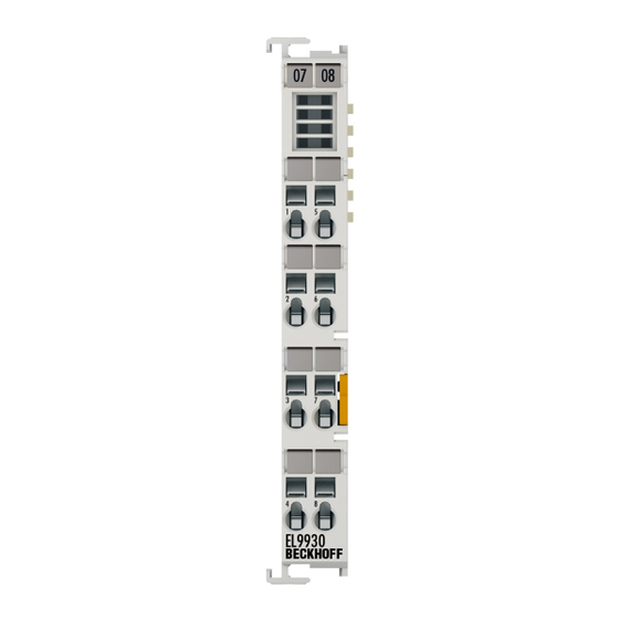
Fig. 1: EL9930 EtherCAT Terminal The EL9930 registers itself as two EtherCAT slaves when the I/O configuration is scanned. Once as EL9930-0000 and once as EL9930-0001. Hence, it is possible to set which PROFIsafe data need to be buffered for both data directions. -
Page 9: Fig. 2 El9930 - Ethercat Communication
Product description The block diagram shows the communication path of the EtherCAT telegram through the EL9930. Fig. 2: EL9930 – EtherCAT communication EL9930 Version: 1.2.0... -
Page 10: Technical Data
Product description Technical data Product designation EL9930 Number of inputs/outputs Supply voltage (SELV/PELV) 24 V (–15% / +20%) Current consumption via E-bus approx. 120 mA Power dissipation of the terminal typically 1 W Dimensions (W x H x D) 12 mm x 100 mm x 68 mm Weight app. 42 g Input process image Dynamic in accordance with the configuration in TwinCAT 3... -
Page 11: Dimensions
Product description Dimensions Fig. 3: EL9930 - Dimensions Width: 12 mm (side-by-side installation) Height: 100 mm Depth: 68 mm EL9930 Version: 1.2.0... -
Page 12: El6930 Connection
Power contact + - not used, no function Power contact - - not used, no function Version: 1.2.0 EL9930... -
Page 13: Operation
• Each bus station must be terminated on the right side with the EL9011 or EL9012 end cap to ensure the protection class and ESD protection. Fig. 5: Spring contacts of Beckhoff I/O components 3.1.3 Transport / storage Use the original packaging in which the components were delivered for transporting and storing the EL components. -
Page 14: Mechanical Installation
Bring the bus system into a safe, de-energized state before starting installation, disassembly or wiring of the devices! 3.1.4.1 Control cabinet / terminal box For operation the EL9930 terminals must be installed in a control cabinet or terminal box with a minimum protection class of IP54 according to IEC 60529. 3.1.4.2 Installation position and minimum distances For the prescribed installation position the mounting rail is installed horizontally and the mating surfaces of the EL/KL terminals point toward the front (see illustration below). -
Page 15: Fig. 7 Attaching On Mounting Rail
To mount the mounting rails with a height of 7.5 mm under the terminals and couplers, you should use flat mounting connections (e.g. countersunk screws or blind rivets). EL9930 Version: 1.2.0... -
Page 16: Electrical Installation
The electric connections between the Bus Coupler and the Bus Terminals are automatically realized by joining the components: Spring contacts (E-bus) The six spring contacts of the E-bus deal with the transfer of the data and the supply of the Bus Terminal electronics. Version: 1.2.0 EL9930... - Page 17 Terminal if the current consumption of your terminals exceeds the maximum current that your Bus Cou- pler can feed to the E-bus supply. The EL9930 has no further contacts such as power contacts or PE contacts. 3.1.5.2 Overvoltage protection If protection against overvoltage is necessary in your plant, provide a surge filter for the voltage supply to the Bus Terminal blocks and the TwinSAFE terminals.
-
Page 18: Configuration Of The Terminal In Twincat
Configuration of the terminal in TwinCAT 3.2.1 Configuration requirements Version 3.1 Build 4024 or higher of the TwinCAT automation software is required for configuring the EL9930. The current version is available for download from the Beckhoff website (www.beckhoff.de). TwinCAT support The EL9930 cannot be used under TwinCAT 2. -
Page 19: Settings In Twincat
PROFIsafe segment on account of the functional principle of EtherCAT. The representation EL9930-0001 (secondary) is a virtual node in the I/O configuration (no real component). Both instances must be placed correctly so that the PROFIsafe segment is limited in accordance with the PROFIsafe policy (see illustration below). -
Page 20: Fig. 11 Process Image - Custom Profisafe Connection
Creation of the IO image of the EL9930-000x The configuration of the IO image of the EL9930-000x is done via the configuration of the EL6910 in the I/O tree (underneath the EtherCAT node.) If a PROFIsafe connection has been configured for the EL6910, the device has an extra tab called PROFIsafe, where the support of the EL9930 components must be activated by checking the checkbox Enable EL9930 Support . -
Page 21: Diagnostic Leds
Fig. 13: Diagnostic LEDs of the EL9930 The EL9930 has two RUN LEDs. Description RUN1 The left RUN LED indicates the EtherCAT status of the EL9930-0000. RUN2 The right RUN LED indicates the EtherCAT status of the EL9930-0001. EL9930 Version: 1.2.0... -
Page 22: Maintenance
Disposal In order to dispose of the device, it must be removed. In accordance with the WEEE Directive 2012/19/EU, Beckhoff takes back old devices and accessories in Germany for proper disposal. Transport costs will be borne by the sender. Return the old devices with the note "for disposal" to: Beckhoff Automation GmbH &... - Page 23 Operation • Electronic parts such as circuit boards must be disposed of in accordance with national electronics scrap regulations. EL9930 Version: 1.2.0...
-
Page 24: Profisafe Configurations
- EP13172092.2 Method and system for detection of errors PROFIsafe configurations without EL9930 The use of the EL9930 is not necessary for the following configurations, because the PROFIsafe telegram leaves the E-bus only via PROFIBUS or PROFINET. The PROFIsafe policy is thus not violated. -
Page 25: Profisafe Configurations With El9930
Fig. 16: Valid PROFIsafe configuration - example 3 PROFIsafe configurations with EL9930 The use of the EL9930 is necessary for the following configurations, because the PROFIsafe telegram would also be transmitted via a fieldbus that is not PROFIBUS or PROFINET. Before leaving the E-bus on EtherCAT, the telegram must be filtered out and copied again into the telegram to the PROFIBUS/ PROFINET master. -
Page 26: Fig. 17: Valid Profisafe Configuration With El9930 - Example 1
TwinCAT IPC with PROFIBUS/PROFINET-EtherCAT Terminal Without the use of the EL9930, the transmission of the PROFIsafe data from the EL6910 to the TwinCAT PC would take place in the following example via the E-bus and EtherCAT. The TwinCAT PC would copy the data in the process image and then send them with the next I/O update via EtherCAT and E-bus to the PROFIBUS/PROFINET master. -
Page 27: Fig. 19: Valid Profisafe Configuration With El9930 - Example 3
If, in the case of a CX controller with a PROFIBUS/PROFINET interface, the E-bus employed is extended by an EK1100 coupler, an EL9930 must be used behind the EL6910 and in front of the EK1100, as otherwise the PROFIsafe telegram would leave the E-bus via EtherCAT. -
Page 28: Appendix
Beckhoff's branch offices and representatives Please contact your Beckhoff branch office or representative for local support and service on Beckhoff products! The addresses of Beckhoff's branch offices and representatives round the world can be found on her internet pages: http://www.beckhoff.com You will also find further documentation for Beckhoff components there. - Page 29 Valid PROFIsafe configuration - example 2................. Fig. 16 Valid PROFIsafe configuration - example 3................. Fig. 17 Valid PROFIsafe configuration with EL9930 - example 1............Fig. 18 Valid PROFIsafe configuration with EL9930 - example 2............Fig. 19 Valid PROFIsafe configuration with EL9930 - example 3............
Need help?
Do you have a question about the EL9930 and is the answer not in the manual?
Questions and answers