Sign In
Upload
Download
Table of Contents
Contents
Add to my manuals
Delete from my manuals
Share
URL of this page:
HTML Link:
Bookmark this page
Add
Manual will be automatically added to "My Manuals"
Print this page
×
Bookmark added
×
Added to my manuals
Manuals
Brands
Beckhoff Manuals
Touch terminals
EL1502
Documentation
Beckhoff EL1502 Documentation
Up/down counter 24 vdc
Hide thumbs
1
2
3
4
5
6
7
8
9
10
11
12
13
14
15
16
17
18
19
20
21
22
23
24
25
26
27
28
29
30
31
32
33
34
35
36
37
38
39
40
41
42
43
44
45
46
47
48
49
50
51
52
53
54
55
56
57
58
59
60
61
62
63
64
65
66
67
68
69
70
71
72
73
74
75
76
77
78
79
80
81
82
83
84
85
86
87
88
89
90
91
92
93
94
95
96
97
98
99
100
101
102
103
104
105
106
107
108
109
110
111
112
113
114
115
116
117
118
119
120
121
122
123
124
125
126
127
128
129
130
131
132
133
134
135
136
137
138
139
140
141
142
143
144
145
146
147
148
149
150
151
152
153
154
155
156
157
158
159
160
161
162
163
164
165
166
167
page
of
167
Go
/
167
Contents
Table of Contents
Bookmarks
Table of Contents
Table of Contents
Fig. 30 EL1502
1 Foreword
Product Overview Up/Down Counter 24 V DC
Notes on the Documentation
Safety Instructions
Documentation Issue Status
Version Identification of Ethercat Devices
Fig. 1 EL5021 el Terminal, Standard IP20 IO Device with Serial/ Batch Number and Revision ID (Since 2014/01)
Fig. 2 EK1100 Ethercat Coupler, Standard IP20 IO Device with Serial/ Batch Number
Fig. 3 CU2016 Switch with Serial/ Batch Number
Fig. 4 EL3202-0020 with Serial/ Batch Number 26131006 and Unique ID-Number 204418
Fig. 5 EP1258-00001 IP67 Ethercat Box with Batch Number/ Date Code 22090101 and Unique Se- Rial Number 158102
Fig. 6 EP1908-0002 IP67 Ethercat Safety Box with Batch Number/ Date Code 071201FF and Unique Serial Number 00346070
Fig. 7 EL2904 IP20 Safety Terminal with Batch Number/ Date Code 50110302 and Unique Serial Num- Ber 00331701
Fig. 8 ELM3604-0002 Terminal with Unique ID Number (QR Code) 100001051 and Serial/ Batch Num- Ber 44160201
2 Product Overview
Introduction
Technical Data
Introduction
El1512
Start
Technical Data
3 Basics Communication
Ethercat Basics
Ethercat Cabling - Wire-Bound
General Notes for Setting the Watchdog
Fig. 11 System Manager Current Calculation
Fig. 12 Ethercat Tab -> Advanced Settings -> Behavior -> Watchdog
Ethercat State Machine
Fig. 13 States of the Ethercat State Machine
Coe Interface
Fig. 14 "Coe Online " Tab
Fig. 15 Startup List in the Twincat System Manager
Fig. 16 Offline List
Fig. 17 Online List
Distributed Clock
4 Mounting and Wiring
Instructions for ESD Protection
Installation on Mounting Rails
Fig. 18 Spring Contacts of the Beckhoff I/O Components
Fig. 19 Attaching on Mounting Rail
Fig. 20 Disassembling of Terminal
Installation Instructions for Enhanced Mechanical Load Capacity
Fig. 21 Power Contact on Left Side
Connection
Connection System
Fig. 22 Standard Wiring
Fig. 23 Pluggable Wiring
Fig. 24 High Density Terminals
Wiring
Fig. 25 Connecting a Cable on a Terminal Point
Shielding
Installation Positions
Fig. 26 Recommended Distances for Standard Installation Position
Positioning of Passive Terminals
Fig. 27 Other Installation Positions
Fig. 28 Correct Positioning
ATEX - Special Conditions (Extended Temperature Range)
Fig. 29 Incorrect Positioning
UL Notice
Leds and Connection
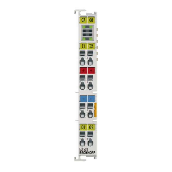
EL1502 - Leds and Connection
Fig. 9 EL1502
EL1512 - Leds and Connection
Fig. 10 EL1512
5 Commissioning
Twincat Quick Start
Fig. 32 Relationship between User Side (Commissioning) and Installation
Fig. 33 Control Configuration with Embedded PC, Input (EL1004) and Output (EL2008)
Fig. 34 Initial Twincat 2 User Interface
Fig. 35 Selection of the Target System
Fig. 36 Specify the PLC for Access by the Twincat System Manager: Selection of the Target System
Fig. 37 Select "Scan Devices
Fig. 38 Automatic Detection of I/O Devices: Selection the Devices to be Integrated
Fig. 39 Mapping of the Configuration in the Twincat 2 System Manager
Fig. 40 Reading of Individual Terminals Connected to a Device
Fig. 41 Twincat PLC Control after Startup
Twincat 2
Twincat 3
Twincat Development Environment
Installation of the Twincat Real-Time Driver
Notes Regarding ESI Device Description
Twincat ESI Updater
Distinction between Online and Offline
OFFLINE Configuration Creation
ONLINE Configuration Creation
Ethercat Subscriber Configuration
General Notes - Ethercat Slave Application
Basic Function Principles
Operating Modes
EL1502 Operating Modes
EL1512 Operating Modes
Fig. 31 EL1512
Process Data
Object Description and Parameterization
EL1502 - Object Description and Parameterization
EL1512 - Object Description and Parameterization
6 Appendix
Ethercat al Status Codes
Firmware Compatibility
Firmware Update El/Es/Em/Epxxxx
Device Description ESI File/Xml
Firmware Explanation
Updating Controller Firmware *.Efw
FPGA Firmware *.Rbf
Simultaneous Updating of Several Ethercat Devices
Restoring the Delivery State
Support and Service
List of Illustrations
Advertisement
Quick Links
1
Product Overview Up/Down Counter 24 V DC
2
El1502 Operating Modes
Download this manual
Documentation
EL1502, EL1512
Up/down Counter 24 VDC
Version:
Date:
3.5
2018-06-08
Table of
Contents
Previous
Page
Next
Page
1
2
3
4
5
Advertisement
Chapters
Table of Contents
3
List of Illustrations
164
Table of Contents
Need help?
Do you have a question about the EL1502 and is the answer not in the manual?
Ask a question
Questions and answers
Related Manuals for Beckhoff EL1502
Touch terminals Beckhoff EL1904 Operating Instructions Manual
Twinsafe terminal with 4 digital fail-safe inputs (46 pages)
Touch terminals Beckhoff EL1904 Operating Instructions Manual
Twinsafe terminal with 4 digital fail-safe inputs (57 pages)
Touch terminals Beckhoff TwinSAFE EL1904 Operating Instructions Manual
Terminal with 4 digital fail-safe inputs (67 pages)
Touch terminals Beckhoff EL1258 Documentation
8 channel digital input/output terminal with time stamp (311 pages)
Touch terminals Beckhoff EL1259 Documentation
8 channel digital input/output terminal with time stamp (311 pages)
Touch terminals beckhoff EL1512 Documentation
Up/down counter 24 vdc (167 pages)
Touch terminals Beckhoff TwinSAFE EL1918 Operating Instructions Manual
Terminal with 8 digital fail-safe inputs (69 pages)
Touch terminals Beckhoff EL1918 Operating Instructions Manual
Twinsafe terminal with 8 digital fail-safe inputs (55 pages)
Touch terminals Beckhoff EL1918 Operation Manual
Twinsafe terminal with 8 digital fail-safe inputs (63 pages)
Touch terminals Beckhoff EL1054 Documentation
Digital input terminals for namur sensors (97 pages)
Touch terminals Beckhoff EL1052 Documentation
Digital input terminals for namur sensors (97 pages)
Touch terminals Beckhoff EL10 Series Documentation
Digital input terminals (106 pages)
Touch terminals Beckhoff EL3773 Documentation
Power monitoring oversampling terminal (179 pages)
Touch terminals Beckhoff ELX1054 Operating Manual
Two- and four-channel digital input terminals for namur sensors, ex i (30 pages)
Touch terminals Beckhoff EL2904 Operating Instructions Manual
Twinsafe terminal with 4 digital fail-safe outputs (51 pages)
Touch terminals Beckhoff EL6631-0010 Manual
Profinet device supplement (82 pages)
Table of Contents
Print
Rename the bookmark
Delete bookmark?
Delete from my manuals?
Login
Sign In
OR
Sign in with Facebook
Sign in with Google
Upload manual
Upload from disk
Upload from URL


Need help?
Do you have a question about the EL1502 and is the answer not in the manual?
Questions and answers