
Related Manuals for Eurotech DynaGate 10-12 Series


Summary of Contents for Eurotech DynaGate 10-12 Series
- Page 1 User manual DynaGATE 10-12 Automotive IoT Edge Gateway TI AM335x, LTE Cat 1 Rev. 0-14 — 31 October 2018 — DYGATE-10-12_UserMan_ENG_0-14 — ENGLISH...
-
Page 2: Trademarks
Revision history Revision Description Date 0-14 Preliminary release 31 October 2018 © 2018 Eurotech SpA - Via Fratelli Solari 3/A - 33020 AMARO (UD) - Italy... -
Page 3: Table Of Contents
DynaGATE 10-12 User manual Rev. 0-14 Contents ONTENTS Trademarks Intended audience of this document Revision history Contents 1 Safety instructions 1.1 Safety messages 1.1.1 Safety messages for hazards with a high level of risk 1.1.2 Safety messages for hazards with a medium level of risk 1.1.3 Safety messages for hazards with a low level of risk 1.2 Other messages 1.2.1 Instructions on how to use the product effectively and avoid any damage... -
Page 4: Com Ports 0 And 1 For Dynagate 10-12-Xy With X
Contents DynaGATE 10-12 User manual Rev. 0-14 7 Interfaces overview 7.1 Front side overview 7.2 Rear side overview 7.2.1 Service Panel interfaces 7.3 Right side overview 7.4 Left side overview 7.5 LED indicators overview 8 Interfaces in detail 8.1 Wi-Fi and Bluetooth (only for versions: -X2, -X5, -X6, -X7) 8.1.1 Wi-Fi specifications 8.1.1.1 2.4 GHZ TX output power 8.1.1.2 5 GHZ TX output power... - Page 5 DynaGATE 10-12 User manual Rev. 0-14 Contents 8.10 Host USB ports 8.10.1 USB 0/1/2 connectors specifications 8.11 Expansion connector 8.11.1 Expansion connector specifications 8.12 TTL Serial console 8.12.1 TTL Serial console connector specifications 8.13 The MicroSD card receptacle 8.13.1 How to insert / remove the MicroSD card in the receptacle 8.14 RTC (Real Time Clock) 8.14.1 The RTC device "/dev/rtc1"...
- Page 6 13 How to compile custom software 13.1 How to set up the toolchain 13.2 How to use the toolchain to compile custom software 14 Eurotech Everyware IoT 14.1 Everyware Software Framework (ESF) 14.2 The ESF Web UI 14.3 The ESF Wires Application 14.4 Everyware Cloud (EC)
-
Page 7: Safety Instructions
Failure to comply with the instructions and warnings contained this document, violates the standards of safety, design, manufacture, and intended use of the product. Eurotech assume no liability for any damage caused by failure to observe the instructions and warnings contained this document. -
Page 8: Safety Messages For Hazards With A Medium Level Of Risk
1 Safety instructions DynaGATE 10-12 User manual Rev. 0-14 1.1.2 Safety messages for hazards with a medium level of risk To indicate a hazard with a medium level of risk which, if not avoided, could result in death or serious injury, the following safety message is used;... -
Page 9: Preventing Electrostatic Discharge
Do not overload the power-points and plugs Use a power supply that meets the requirements stated on the identification label of the product. In case of uncertainties about the required power supply, contact the Eurotech Technical Support Team (for more information see "Receiving technical assistance"... - Page 10 (This page has been intentionally left blank)
-
Page 11: Receiving Technical Assistance
5. Ship the product to Eurotech following the information received from the RMA Department. NOTICE Any product returned to Eurotech, that is found to be damaged due to inadequate packaging, will not be covered by the warranty. 11 / 94... - Page 12 (This page has been intentionally left blank)
-
Page 13: Conventions
Negative signal; Negative signal in differential pair 3.3 V signal level 5 V signal level No Connection Reserved Use is reserved to Eurotech Conventions for signal types Convention Description Signal is an input to the system Signal is an output from the system... - Page 14 (This page has been intentionally left blank)
-
Page 15: Getting Started
OEM application. For detailed instructions, and sample applications for developing device applications using ESF on Eurotech platforms, see: http://esf.eurotech.com/docs. 5. Install the DynaGATE 10-12. The DynaGATE 10-12 is lightweight, compact, and easy to install. - Page 16 (This page has been intentionally left blank)
-
Page 17: Product Overview
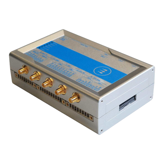
All interfaces are suitable for applications with a high level of shock and vibration: front panel USB ports feature high retention connectors and all other signals are delivered by locking connectors or screw-flange terminal blocks. For further details visit www.eurotech.com. Figure 5.1 - Example of DynaGATE 10-12, front side The features availability depends on the product versions... -
Page 18: Intended Use And Not Allowed Uses Of The Product
5 Product overview DynaGATE 10-12 User manual Rev. 0-14 Intended use and not allowed uses of the product NOTICE Install this product in a secured location, only accessible to authorized personnel (for example in a cabinet / technical compartment). This product is intended for professional use and must only be installed by qualified personnel. 5.2.1 Intended use The DynaGATE 10-12 is a family of IoT Edge Gateways designed to deliver LTE connectivity with 2G/3G... -
Page 19: Technical Specifications
DynaGATE 10-12 User manual Rev. 0-14 5 Product overview Technical specifications The DynaGATE 10-12 is available in several versions: from DynaGATE 10-12-X1 to DynaGATE 10-12-X7; for example DynaGATE 10-12-53. They have the following specifications, according to the respective versions: Specifications Description according to DynaGATE 10-12-XY versions Processor TI AM3352, 1 GHz, 1 Core... - Page 20 5 Product overview DynaGATE 10-12 User manual Rev. 0-14 Specifications Description according to DynaGATE 10-12-XY versions LEDs 1x Power, 1x Mobile Connectivity, 4x Programmable Buttons 1x Reset, 1x Programmable SIM slot 2x Micro-SIM (user accessible) Power Input Nominal: 12 or 24 VDC; Range: 9 to 36 VDC with transient protection and Vehicle Ignition Sense Consumption 2 W typical;...
-
Page 21: Product Labels
The following label is placed on the product: Label example Label type and content Label position Part Number and Serial Number Label On the underside of Eurotech logo the product Manufacturer name Manufacturer address (only for EU versions) Product number Model number (xx = product version) - Page 22 (This page has been intentionally left blank)
-
Page 23: Norms And Certifications
6.2.1 Modification statement Eurotech has not approved any changes or modifications to this product by the user. Any changes or modifications could void the user’s authority to operate the product. FCC marking Some versions of the product described in this document are FCC marked; for further information see "Technical specifications"... -
Page 24: Rf Radiation Exposure Statement
6 Norms and certifications DynaGATE 10-12 User manual Rev. 0-14 1. L’appareil ne doit pas produire de brouillage; 2. L’appareil doit accepter tout brouillage radioélectrique subi, même si le brouillage est susceptible d’en compromettre le fonctionnement. This radio transmitter 21442-MRG1012 has been approved by Innovation, Science and Economic Development Canada to operate with the antenna types listed below, with the maximum permissible gain indicated. -
Page 25: Fcc Class B Digital Device Notice
DynaGATE 10-12 User manual Rev. 0-14 6 Norms and certifications Cet appareil et son (ses) antenne(s) ne doivent pas être co-localisés ou utilisés en conjonction avec une autre antenne ou un autre émetteur, sauf en conformité avec les procédures du produit multi-émetteur de la FCC. -
Page 26: Restrictions On 5 Ghz Wi-Fi Usage
6 Norms and certifications DynaGATE 10-12 User manual Rev. 0-14 Restrictions on 5 GHz Wi-Fi usage Channel Number Frequency (MHz) Europe (ETSI) North America (FCC) 5180 Indoor Usage Only Indoor Usage Only 5200 Indoor Usage Only Indoor Usage Only 5220 Indoor Usage Only Indoor Usage Only 5240... -
Page 27: Antennas List
DynaGATE 10-12 User manual Rev. 0-14 6 Norms and certifications Antennas list The DynaGATE 10-12 has been certified with the following antennas: Antenna Types DynaGATE 10-12-XY Versions Manufacturer and Part Number Wi-Fi / Bluetooth -X2, -X5, -X6 Linx Technologies ANT-DB1-RAF-RPS Taoglas MA.950.W.A.LBICG.005 Mobile connectivity -X3, -X5, -X5, -X6 Taoglas GSA.8827.A101111... - Page 28 (This page has been intentionally left blank)
-
Page 29: Interfaces Overview
DynaGATE 10-12 User manual Rev. 0-14 7 Interfaces overview NTERFACES OVERVIEW Front side overview The front side layout is the following: Figure 7.1 - Front panel interfaces layout Ref# Description 2.4 GHz Wi-Fi / Bluetooth antenna connector (only for versions: -X2, -X5, -X6, -X7) Internal Main Mobile antenna connector (only for versions: -X3, -X4, -X5, -X6, -X7) Internal Global Navigation Satellite System (GNSS) antenna connector Internal Diversity Mobile antenna connector (only for versions: -X3, -X4, -X5, -X6, -X7) -
Page 30: Rear Side Overview
7 Interfaces overview DynaGATE 10-12 User manual Rev. 0-14 Rear side overview The rear side layout is the following: Figure 7.2 - Rear panel interfaces layout Ref# Description Ethernet ETH 1 connector Ethernet ETH 0 connector USB 0 connector USB 1 connector Service Panel Power IN connector Table 7.2 - Rear panel interfaces description... -
Page 31: Service Panel Interfaces
DynaGATE 10-12 User manual Rev. 0-14 7 Interfaces overview 7.2.1 Service Panel interfaces The interfaces available in the Service Panel are the following: Figure 7.3 - Service Panel interfaces layout Ref# Description Combo MicroSD + MicroSIM cards receptacle; pull-lever Boot selection jumper DIP-switch for serial ports configuration Programmable pushbutton TTL Serial console... -
Page 32: Right Side Overview
7 Interfaces overview DynaGATE 10-12 User manual Rev. 0-14 Right side overview The right side layout is the following: Figure 7.4 - Expansion connector Ref# Description Expansion Connector Table 7.4 - Expansion connector description For further details see: "Expansion connector" on page 53 32 / 94... -
Page 33: Left Side Overview
DynaGATE 10-12 User manual Rev. 0-14 7 Interfaces overview Left side overview The left side layout is the following: Figure 7.5 - Expansion USB connector layout Ref# Description 2.0 Host USB connector (ready to interface optional USB accessories, e.g.: ReliaCELL 10-20) Table 7.5 - Expansion USB connector description 33 / 94... -
Page 34: Led Indicators Overview
7 Interfaces overview DynaGATE 10-12 User manual Rev. 0-14 LED indicators overview The LED indicators are placed on the bottom side of the product. They are the following: Figure 7.6 - LED indicators layout Ref# Color USER1 (General purpose) Green USER2 (General purpose) Green USER3 (General purpose) -
Page 35: Interfaces In Detail
DynaGATE 10-12 User manual Rev. 0-14 8 Interfaces in detail NTERFACES IN DETAIL Wi-Fi and Bluetooth (only for versions: -X2, -X5, -X6, -X7) The DynaGATE 10-12 provides the following Wi-Fi / Bluetooth functionality: 2.5 GHz Wi-Fi 802.11a,b,g,n / BLE 4.2 BLE Bluetooth 5 GHz Wi-Fi 802.11a,b,g,n The internal circuitry allows for 2.5 GHz Wi-Fi and Bluetooth coexistence. -
Page 36: Bluetooth Specifications
8 Interfaces in detail DynaGATE 10-12 User manual Rev. 0-14 8.1.2 Bluetooth specifications Supports Bluetooth 4.2 Includes concurrent operation and built -in coexisting and prioritization handling of Bluetooth, BLE, audio processing and WLAN Dedicated Audio processor supporting on chip SBC encoding + A2DP: Assisted A2DP (A3DP) support - SBC encoding implemented internally Assisted WB-Speech (AWBS) support - modified SBC codec implemented internally 8.1.3... -
Page 37: Internal Mobile Connectivity (Only For Versions: -X3, -X4, -X5, -X6, -X7)
DynaGATE 10-12 User manual Rev. 0-14 8 Interfaces in detail Internal mobile connectivity (only for versions: -X3, -X4, - X5, -X6, -X7) The DynaGATE 10-12 supports the following TELIT LE910 V2 modem variants, according to product versions based on the geographic area of usage: DynaGATE 10-12-XY Version TELIT LE910 V2 variant Technology... -
Page 38: Main Antenna Requirements
8 Interfaces in detail DynaGATE 10-12 User manual Rev. 0-14 8.2.1.5 Main antenna requirements NA version Feature Value Frequency range Depending by the frequency band(s) provided by the network operator Bandwidth 140 MHz in LTE/WCDMA Band 2 445 MHz in LTE Band 4 70 MHz in LTE/WCDMA Band 5 47 MHz in LTE Band 12 41 MHz in LTE Band 13... -
Page 39: Second Antenna Requirements (For Antenna Diversity)
DynaGATE 10-12 User manual Rev. 0-14 8 Interfaces in detail 8.2.1.6 Second antenna requirements (for antenna diversity) NA version Feature Value Frequency range Depending by the frequency band(s) provided by the network operator Bandwidth 60 MHz in LTE/WCDMA Band 2 45 MHz in LTE Band 4 25 MHz in LTE/WCDMA Band 5 15 MHz in LTE Band 12... -
Page 40: Internal Mobile Antennas Connectors Specifications
8 Interfaces in detail DynaGATE 10-12 User manual Rev. 0-14 8.2.2 Internal mobile antennas connectors specifications Specifications are the same for both the following: Main Antenna Connector Diversity Antenna Connector Connector Layout: Connector Pinout: Pin # Description Female inner pin contact Female connector body (outer thread) Connector Specifications: SMA connector... -
Page 41: The Microsim Card Receptacles
DynaGATE 10-12 User manual Rev. 0-14 8 Interfaces in detail The MicroSIM card receptacles The DynaGATE 10-12 includes the following MicroSIM card receptacles in the Service Panel: 1st MicroSIM card receptacle: Integrated in a Combo MicroSD + MicroSIM cards receptacle (pull- lever) on the top side of the circuit board 2nd MicroSIM card receptacle: On the bottom side of the circuit board (push-pull) -
Page 42: If You Are Using The Receptacle On The Bottom Side Of The Circuit Board
8 Interfaces in detail DynaGATE 10-12 User manual Rev. 0-14 8.3.1.2 If you are using the receptacle on the bottom side of the circuit board To insert the MicroSIM card, push it in the holder with the contacts facing up, and the cut corner facing inwards. -
Page 43: Internal Gnss
DynaGATE 10-12 User manual Rev. 0-14 8 Interfaces in detail Internal GNSS The DynaGATE 10-12 provides the following GNSS functionality: DynaGATE 10-12-XY versions GNSS functionality X ≤ 3 Internal; 72 channels GPS, Galileo, GLONASS, BeiDou X ≥ 4 Internal Untethered Dead Reckoning; 72 channels GPS, Galileo, GLONASS, BeiDou The GNSS outputs NMEA data which can be read by applications directly. -
Page 44: Digital I/Os
8 Interfaces in detail DynaGATE 10-12 User manual Rev. 0-14 Digital I/Os The DynaGATE 10-12 provides the following Digital I/Os: 2x Digital Input: 36 V, 1 kV Optoinsulated 2x Digital Output: 40 V AC/DC, 1 kV Optoinsulated, 500 mA, 1 kHz Max Switching The Digital I/Os connector is available on the front side. -
Page 45: Insulated Digital Outputs
DynaGATE 10-12 User manual Rev. 0-14 8 Interfaces in detail 8.5.2 Insulated Digital Outputs 8.5.2.1 Electrical specifications The table below shows the electrical specifications of the digital outputs: Characteristic Value Maximum Voltage 40 V Maximum Current 500 mA Output ON Resistance Typical: 0.83 Ohm Maximum: 2.50 Ohm >Maximum switching frequency... -
Page 46: Com Ports 0 And 1 For Dynagate 10-12-Xy With X ≤ 3
8 Interfaces in detail DynaGATE 10-12 User manual Rev. 0-14 COM ports 0 and 1 for DynaGATE 10-12-XY with X ≤ 3 The DynaGATE 10-12 provides the following COM ports: 2x RS-232/485: COM 0/1; Surge protected, RS-485 termination and fail-safe resistors (Default: RS-232) COM ports specifications: The COM ports are surge protected... -
Page 47: Com Connector Specifications
DynaGATE 10-12 User manual Rev. 0-14 8 Interfaces in detail 8.6.3 COM connector specifications Connector Layout: Connector Pinout: Pin # Signal Type Description COM 0: TX/D- COM port 0: RS-232: Transmit Data RS-485: B (D- Line) Connector Specifications: COM 0: RX/D+ COM port 0: Base strip, Header RS-232: Receive Data... -
Page 48: Note For Termination Resistors (Only For Com 1 In Rs-485 Mode)
8 Interfaces in detail DynaGATE 10-12 User manual Rev. 0-14 COM ports 0 and 1 for DynaGATE 10-12-XY with X ≥ 4 The DynaGATE 10-12 provides the following COM ports: 1x RS-422/485: COM 0; Surge protected, Insulated, Full Duplex / Half Duplex (Default: RS-422 Full Duplex) 1x RS-232/485: COM 1;... -
Page 49: Com Connector Specifications
DynaGATE 10-12 User manual Rev. 0-14 8 Interfaces in detail 8.7.3 COM connector specifications Connector Layout: Connector Pinout: Pin # Signal Type Description COM 0: Y/D+ COM port 0: RS-422: Y (+OUT) RS-485: A (D+ Line) Connector Specifications: COM 0: Z/D- COM port 0: Base strip, Header RS-422: Z (-OUT) -
Page 50: Can Ports 0 And
8 Interfaces in detail DynaGATE 10-12 User manual Rev. 0-14 CAN ports 0 and 1 The DynaGATE 10-12 provides 2x CAN (Controller Area Network) ports compliant with the CAN Specification 2.0, Parts A and B: CAN 0 CAN 1 The CAN 0/1 connectors are available on the front side. Notes about CAN power supply: The DynaGATE 10-12 can supply power to the 2 CAN ports: 100 mA @ 5V (each port) CAN power can be enabled / disabled by software... -
Page 51: Ethernet Eth 0 And 1
DynaGATE 10-12 User manual Rev. 0-14 8 Interfaces in detail Ethernet ETH 0 and 1 The DynaGATE 10-12 provides 2x 10/100 Mbps Ethernet ports for wired network connectivity: ETH 0 ETH 1 The ETH 0/1 connectors are available on the rear side. 8.9.1 Ethernet specifications Feature... -
Page 52: Host Usb Ports
8 Interfaces in detail DynaGATE 10-12 User manual Rev. 0-14 8.10 Host USB ports The DynaGATE 10-12 provides 3x Host 2.0 USB ports (Noise and Surge Protected) for general purpose applications: USB 0 on the front side; max load: 500 mA (high retention connector) USB 1 on the front side;... -
Page 53: Expansion Connector
DynaGATE 10-12 User manual Rev. 0-14 8 Interfaces in detail 8.11 Expansion connector The DynaGATE 10-12 provides an expansion connector for the following: Additional USB OTG interface S Audio interface GPIO expansion interface C interface SPI interface The expansion connector is available on the right side. 8.11.1 Expansion connector specifications Connector Layout:... -
Page 54: Ttl Serial Console
8 Interfaces in detail DynaGATE 10-12 User manual Rev. 0-14 8.12 TTL Serial console The DynaGATE 10-12 provides a 3.3 V TTL compatible Serial console port in the Service Panel. The voltage levels are the following: Log 1 (Hi): 2.0 to 3.3 V Log 0 (Low): 0 to 0.8 V 8.12.1 TTL Serial console connector specifications... -
Page 55: The Microsd Card Receptacle
DynaGATE 10-12 User manual Rev. 0-14 8 Interfaces in detail 8.13 The MicroSD card receptacle The DynaGATE 10-12 includes a MicroSD card receptacle in the Service Panel. It is integrated in a Combo MicroSD + MicroSIM cards receptacle (pull-lever) on the top side of the circuit board. -
Page 56: Rtc (Real Time Clock)
8 Interfaces in detail DynaGATE 10-12 User manual Rev. 0-14 8.14 RTC (Real Time Clock) The DynaGATE 10-12 includes the following two RTC (Real Time Clocks) devices: RTC device Description /dev/rtc0 Internal (in the CPU SoC) Reserved /dev/rtc1 External (I2C-based RTC device) Wake up the DynaGATE 10-12 from a deep low power Default RTC used by Linux state... -
Page 57: How To Supply Power To The Product
DynaGATE 10-12 User manual Rev. 0-14 9 How to supply power to the product OW TO SUPPLY POWER TO THE PRODUCT NOTICE This product is not provided with any ON/OFF switch. The Power IN connector is the disconnecting means from the power supply network. Power supply specifications Power supply Nominal: 12 or 24 VDC;... -
Page 58: How To Supply Power And Turn On The Product
Only start the product with a power supply that meets the requirements stated on the voltage label. In case of uncertainties about the required power supply, contact the Eurotech Technical Support Team (see the back cover for full contact details) or the electricity authority. -
Page 59: How To Turn Off The Product
DynaGATE 10-12 User manual Rev. 0-14 9 How to supply power to the product How to turn OFF the product To turn the DynaGATE 10-12 OFF follow these steps: 1. Login the Administration console and run the shutdown command. The system turns itself OFF 2. - Page 60 (This page has been intentionally left blank)
-
Page 61: The Software
10 The Software OFTWARE 10.1 The Linux OS distribution Eurotech can provide a Linux operating systems based on Yocto framework (www.yoctoproject.org) as well as an SDK for application development. All the documentation for the developer is available from:www.yoctoproject.org/documentation. 10.2 The bootloader procedure The bootloader procedure is the following: 1. - Page 62 (This page has been intentionally left blank)
-
Page 63: How To Access Interfaces Under Linux
DynaGATE 10-12 User manual Rev. 0-14 11 How to access interfaces under Linux OW TO ACCESS INTERFACES UNDER INUX Interfaces availability depends on the product version. NOTICE If Everyware Software Framework (ESF) is installed, it will manage the network interfaces, mobile modem, Bluetooth adapter and GPIOs. -
Page 64: How To Determine The Operating System Version Installed
11 How to access interfaces under Linux DynaGATE 10-12 User manual Rev. 0-14 11.2 How to determine the Operating System version installed To determine the Operating System version installed, enter the following command: eurotech_versions Example output: eth_name_bsp: xxx eth_vers_bsp: Operating System version eth_partno_bsp: unknown eth_serial_number: xxx eth_model: xxx... -
Page 65: Cellular Modem
DynaGATE 10-12 User manual Rev. 0-14 11 How to access interfaces under Linux 11.6 Cellular modem The DynaGATE 10-12 supports the following TELIT LE910 V2 modem variants, according to product versions based on the geographic area of usage: DynaGATE 10-12-XY Version TELIT LE910 V2 variant Technology -X3, -X5... -
Page 66: How To Select The Verizon Firmware
11 How to access interfaces under Linux DynaGATE 10-12 User manual Rev. 0-14 11.6.2.2 How to select the Verizon firmware To select the Verizon firmware, use the following command: telit-he910 chat ‘AT#FWSWITCH=1,1’ 66 / 94... -
Page 67: Gnss
DynaGATE 10-12 User manual Rev. 0-14 11 How to access interfaces under Linux 11.7 GNSS The DynaGATE 10-12 exposes the GNSS as follows: /dev/ttyS5 You need to enable the GNSS before it will work. To enable the GNSS, enter the following command: gpio_utility gpio81 1 To prove that the positioning is working, dump the serial port output by entering the following commands:... -
Page 68: Can Ports
11 How to access interfaces under Linux DynaGATE 10-12 User manual Rev. 0-14 11.8 CAN ports The DynaGATE 10-12 exposes the CAN ports as follows: CAN 0 port: can0 CAN 1 port: can1 CAN ports are added through the SocketCAN kernel extension. For further information on SocketCAN refer to the Linux kernel documentation: www.kernel.org/doc/Documentation/networking/can.txt 11.8.1... -
Page 69: Com Ports 0 And 1, Console Port
DynaGATE 10-12 User manual Rev. 0-14 11 How to access interfaces under Linux 11.9 COM ports 0 and 1, Console port The DynaGATE 10-12 exposes the COM ports as follows: COM port 0: /dev/ttyS4 (available on the front panel) COM port 1: /dev/ttyS3 (available on the front panel) Console port /dev/ttyS0 (available in the Service Panel) -
Page 70: How To Implement The Ioctl In The Source Code To Configure The Com Ports
11 How to access interfaces under Linux DynaGATE 10-12 User manual Rev. 0-14 11.9.1.2 How to implement the ioctl in the source code to configure the COM ports To implement the ioctl in the source code, enter the following commands: /*Ioctl to read */ #define TIOCGRS485 0x542E... - Page 71 DynaGATE 10-12 User manual Rev. 0-14 11 How to access interfaces under Linux Example: Configuring a serial port in RS-232 mode ser_port_name can be either /dev/ttyO3 or /dev/ttyO4. struct serial_rs485 rs485conf; unsigned int rs_mode_mask=(SER_HIZ_ENABLED|SER_RS485_ENABLED|SER_RS485_ INVERT|SER_RS485_RTS_ON_SEND|SER_RS485_RTS_AFTER_SEND); unsigned int set_flags=0; unsigned int set_flags_mask=rs_mode_mask; int fd;...
-
Page 72: How To Test A Serial Port
11 How to access interfaces under Linux DynaGATE 10-12 User manual Rev. 0-14 Example: Configuring a serial port in RS-485 mode ser_port_name can be either /dev/ttyO3 or /dev/ttyO4. struct serial_rs485 rs485conf; unsigned int rs_mode_mask=(SER_HIZ_ENABLED|SER_RS485_ENABLED|SER_RS485_ INVERT|SER_RS485_RTS_ON_SEND|SER_RS485_RTS_AFTER_SEND); unsigned int set_flags=(SER_RS485_INVERT|SER_RS485_ENABLED|SER_RS485_RTS_ON_ SEND); unsigned int set_flags_mask=rs_mode_mask; int fd;... -
Page 73: 11.10 Digital I/Os
DynaGATE 10-12 User manual Rev. 0-14 11 How to access interfaces under Linux 11.10 Digital I/Os The DynaGATE 10-12 exposes the Digital I/Os (GPIOs) as follows: Digital Input 1: /sys/class/gpio/gpio26/value Digital Input 2: /sys/class/gpio/gpio27/value Digital Output 1: /sys/class/gpio/gpio87/value Digital Output 2: /sys/class/gpio/gpio89/value To manage these GPIOs, see "How to drive the GPIOs: the GPIO utility"... -
Page 74: How To Enable The 3.3V And 5V Power Supply On Expansion Connector
11 How to access interfaces under Linux DynaGATE 10-12 User manual Rev. 0-14 11.14 How to enable the 3.3V and 5V power supply on expansion connector 3.3V and 5V are OFF by default and are controlled driving specific GPIO’s. To control the 3.3V, enter the following commands: #turn on 3.3V gpio_utility gpio71 1 #turn off 3.3V... -
Page 75: 11.15 Rtc
DynaGATE 10-12 User manual Rev. 0-14 11 How to access interfaces under Linux 11.15 RTC The DynaGATE 10-12 exposes the RTC as follows: RTC: /dev/rtc1 /dev/rtc1 offers three read-only timestamp registers: Timestamp register What it contains sys/class/rtc/rtc1/device/timestamp1 Reserved data sys/class/rtc/rtc1/device/timestamp2 The timestamp that the system last lost power (only if a successful initialization has been achieved) sys/class/rtc/rtc1/device/timestamp3... -
Page 76: 11.16 Watchdog
11 How to access interfaces under Linux DynaGATE 10-12 User manual Rev. 0-14 11.16 Watchdog The DynaGATE 10-12 exposes the watchdog as follows: Watchdog: /dev/watchdog1 11.16.1 How to manage the watchdog using the C programming language To manage the watchdog using the C programming language enter the following commands: Int interval;... -
Page 77: For Further Information
DynaGATE 10-12 User manual Rev. 0-14 11 How to access interfaces under Linux 11.16.3 For further information For further information on Linux support for watchdog, see: www.kernel.org/doc/Documentation/watchdog/watchdog-api.txt 11.17 Accelerometer The DynaGATE 10-12 is provided with an accelerometer sensor. To print the information from the accelerometer, including an update every time movement is detected, use the following command: evtest /dev/input/event0 Example output:... -
Page 78: 11.18 Internal Temperature Sensor
11 How to access interfaces under Linux DynaGATE 10-12 User manual Rev. 0-14 11.18 Internal temperature sensor The DynaGATE 10-12 is provided with a sensor that measures the temperature inside the product. To read the internal temperature, enter the following command: cat /sys/class/hwmon/hwmon0/temp1_input 11.19 The Programmable pushbutton The programmable pushbutton is sensed by a Linux daemon which executes a shell script every time the... -
Page 79: How To Log In The Administration Console
To log in using eth0, complete the following steps: This cable adapter has an end provided with a Male USB connector type A, and the other end provided with a 3-pin, 1.25 pitch, female receptacle housing. Contact Eurotech for further information. 79 / 94... -
Page 80: How To Login Via The Eth1 Port
"The default credentials" on the previous page). 12.4 How to change your security settings For security reasons, Eurotech recommends you to change the Linux 'root' password after your initial setup. To change your Linux password, complete the following steps: 1. Login using the console port 2. -
Page 81: How To Compile Custom Software
1. Make sure you're using the correct toolchain version corresponding to the Yocto image installed on your gateway. The latest toolchain and Yocto image for your DynaGATE 10-12 are available here: https://eurotech.github.io/linux-releases/ 2. Download the binary file (x86_64 version tested) on a Virtual/physical machine running Ubuntu (14.04 tested), execute it and select appropriate installation options 3. - Page 82 (This page has been intentionally left blank)
-
Page 83: Eurotech Everyware Iot
ESF allows the connection and communication with field devices (close to data sources), thanks to already tested libraries for field protocol communication, the visual IoT Edge Computing applications development and the connection with leading IoT Cloud Services such as Everyware Cloud (Eurotech IoT Integration Platform) , Eclipse Kapua, AWS IoT and Microsoft Azure IoT. -
Page 84: The Esf Web Ui
14 Eurotech Everyware IoT DynaGATE 10-12 User manual Rev. 0-14 14.2 The ESF Web UI ESF provides a web-based user interface: ESF Web UI. The ESF Web UI provides several functionalities such as: Monitor the gateway status Manage the network configuration Oversee the installed application(s) and services. -
Page 85: The Esf Wires Application
DynaGATE 10-12 User manual Rev. 0-14 14 Eurotech Everyware IoT 14.3 The ESF Wires Application ESF provides also a dataflow programming model: Wires. Wires simplifies the development of Edge Computing Applications leveraging reusable configurable components. In the dataflow programming model, the application logic is expressed as a directed graph (flow) where each node can have inputs, outputs and independent processing units. -
Page 86: Everyware Cloud (Ec)
14.4 Everyware Cloud (EC) Eurotech’s Everyware™ Cloud (EC) is an IoT Integration Platform that simplifies system and data management by connecting distributed devices over secure and reliable cloud services. Everyware Cloud allows you to connect, configure and manage devices through all the lifecycle, from deployment through maintenance to retirement. -
Page 87: Mechanical Specifications
DynaGATE 10-12 User manual Rev. 0-14 15 Mechanical specifications ECHANICAL SPECIFICATIONS 15.1 Product mechanical dimensions The product electronics are housed in an aluminum alloy enclosure having the following dimensions: 139 (L) x 118 (W) x 52 (H); mm - Antennas Connectors and Mounting Bracket included. All dimensions are in millimeters. - Page 88 (This page has been intentionally left blank)
-
Page 89: How To Install The Product
DynaGATE 10-12 User manual Rev. 0-14 16 How to install the product OW TO INSTALL THE PRODUCT NOTICE This product must only be installed by qualified personnel. Install this product in a secured location, only accessible to authorized personnel (for example in a cabinet / technical compartment). - Page 90 (This page has been intentionally left blank)
-
Page 91: How To Maintain The Product
DynaGATE 10-12 User manual Rev. 0-14 17 How to maintain the product OW TO MAINTAIN THE PRODUCT Periodically inspect the product to verify its integrity and to ensure proper operation. To maintain the product, complete the following steps: 1. Carefully read and understand the instructions contained in the section "Safety instructions"... - Page 92 (This page has been intentionally left blank)
-
Page 93: Notes
DynaGATE 10-12 User manual Rev. 0-14 Notes OTES 93 / 94... - Page 94 Via Fratelli Solari, 3/a For your Eurotech local contact refer to: eurotech.com/contacts 33020 Amaro (UD) - Italy Tel: +39 0433.485.411 For the Eurotech Global Support Centre refer to: support.eurotech.com Fax: +39 0433.485.499 Email: welcome@eurotech.com For the Eurotech Download Area refer to: eurotech.com/download...
Need help?
Do you have a question about the DynaGate 10-12 Series and is the answer not in the manual?
Questions and answers