
Related Manuals for Eurotech ReliaGATE 10-14 Series


Summary of Contents for Eurotech ReliaGATE 10-14 Series
- Page 1 User manual ReliaGATE 10-14 Multi-service IoT Edge Gateway - NXP i.MX8, LTE Cat 1 Rev. 0-10 — 20 October 2020 — REGATE-10-14_Man_ENG_0-10 — ENGLISH...
-
Page 2: Trademarks
6.2 "Intended use and not allowed uses of the product" 6.3 "Technical specifications" 11.1 "Default credentials" 12.7.1 "How to select the MicroSIM card holder to use" © 2020 Eurotech SpA - Via Fratelli Solari 3/A - 33020 AMARO (UD) - Italy... -
Page 3: How To Get Started
For more information see: "Safety instructions" on page 9. Whenever in doubt regarding the correct understanding of this document, contact the Eurotech Technical Support. For more information see: "How to receive technical assistance" on page 17 2. - Page 4 (This page has been intentionally left blank)
-
Page 5: Table Of Contents
ReliaGATE 10-14 User manual Rev. 0-10 Contents ONTENTS Trademarks Intended audience of this document Revision history How to get started Contents 1 Safety instructions 1.1 Warning messages 1.1.1 Warning messages for harm to persons 1.1.2 Warning messages for damage to property 1.2 Warning: power supply safety 1.3 Caution: wireless safety 1.4 Caution: product's surfaces may become hot... - Page 6 Contents ReliaGATE 10-14 User manual Rev. 0-10 7.2.2 FCC Class B Digital Device Notice 7.2.3 FCC restrictions on 5 GHz Wi-Fi usage 7.2.4 ISED Canada Regulatory Notices 7.2.5 ISED Class B Digital Device Notice 7.2.6 Responsible parties: Canadian Representative contact information 7.2.7 RF Radiation Exposure Statement 7.2.8 Labeling Information 7.3 Antennas list...
- Page 7 ReliaGATE 10-14 User manual Rev. 0-10 Contents 9.11.2 The RTC backup supercap 9.12 Case Intrusion 9.13 TPM 9.14 Watchdog 10 The Software 10.1 The Linux OS Distribution 10.2 Ensure power supply during installation and update 10.3 Docker 10.4 Microsoft IoT Edge 10.5 System Firewall 10.6 Partition layout 11 How to access the Administration Console...
- Page 8 Contents ReliaGATE 10-14 User manual Rev. 0-10 15 Power supply. How to turn ON/OFF and reset the product 15.1 Power supply specifications 15.2 Power IN connector specifications 15.3 How to supply power and turn ON the product 15.4 How to turn OFF the product 15.5 How to reduce the power consumption of the product 15.6 How to hardware reset the product 16 How to maintain the product...
-
Page 9: Safety Instructions
Failure to comply with the instructions and warnings contained in this document, violates the standards of safety, design, manufacture, and intended use of the product. Eurotech assume no liability for any damage caused by failure to observe the instructions and warnings contained in this document. -
Page 10: Warning Messages For Damage To Property
"Earth connection terminal" on page 57 8. Use a power supply that meets the product requirements and complies with the relevant standards and regulations. In case of uncertainties, contact the Eurotech Technical Support Team (for more information see "How to receive technical assistance" on page 17) -
Page 11: Caution: Product's Surfaces May Become Hot
ReliaGATE 10-14 User manual Rev. 0-10 1 Safety instructions Caution: product's surfaces may become hot Depending on the operating environment temperature, product's surfaces may become hot, creating a burn hazard. Always allow the product's surfaces to cool before touching them. 11 / 90... - Page 12 (This page has been intentionally left blank)
-
Page 13: Consignes De Securite
Eurotech rejette toute responsabilité pour les dommages causés en cas de non-respect des instructions et des avertissements contenus dans ce document. En cas de doute sur la compréhension de ce document, contacter le Support Technique d’ Eurotech (pour plus d’informations voir "Comment obtenir une assistance technique"... -
Page 14: Messages D'avertissement Relatifs Aux Dommages Matériels
"Earth connection terminal" page 57 8. Utiliser une alimentation électrique conforme aux exigences du produit et conforme aux normes et réglementations en vigueur. En cas d'incertitude, contacter l'équipe d'assistance technique d'Eurotech (pour plus d'informations, voir "Comment obtenir une assistance technique" page 9. -
Page 15: Attention: Les Surfaces Du Produit Peuvent Devenir Chaudes
ReliaGATE 10-14 User manual Rev. 0-10 2 Consignes de securite Attention: les surfaces du produit peuvent devenir chaudes Selon la température ambiante lors de l’utilisation, les surfaces du produit peuvent devenir brûlantes, engendrant un risque de brûlure. Laisser toujours les surfaces du produit refroidir avant de les toucher. - Page 16 (This page has been intentionally left blank)
-
Page 17: How To Receive Technical Assistance
3. Wait for the reply from the Eurotech Technical Support with the information you required How to send a product for repair Any product returned to Eurotech, that is found to be damaged due to inadequate packaging, will not be covered by the warranty. - Page 18 (This page has been intentionally left blank)
-
Page 19: Comment Obtenir Une Assistance Technique
3. Attendre la réponse de l'équipe de support avec les informations requises Comment retourner un produit en service après vente Tout produit renvoyé à Eurotech, qui se trouve endommagé en raison d'un emballage inadéquat, ne sera pas couvert par la garantie. - Page 20 (This page has been intentionally left blank)
-
Page 21: Conventions Used
Negative signal; Negative signal in differential pair 3.3 V signal level 5 V signal level No Connection Reserved Use is reserved to Eurotech Conventions for signal types Convention Description Signal is an input to the system Signal is an output from the system... - Page 22 (This page has been intentionally left blank)
-
Page 23: Product Overview
Eclipse Kura, the open source Java/OSGi middleware for IoT Edge Gateways. Distributed and supported by Eurotech, ESF supports ready-to-use field protocols (including Modbus, OPC-UA, S7), MQTT connectivity, web-based visual data flow programming and deep configuration. ESF is also integrated with Everyware Cloud (EC), Eurotech IoT Integration Platform (separately available), enabling advanced diagnostics, provisioning, and full remote device access and management. -
Page 24: Intended Use And Not Allowed Uses Of The Product
6 Product overview ReliaGATE 10-14 User manual Rev. 0-10 Intended use and not allowed uses of the product The product is intended for professional use and must be installed by qualified personnel only. The product must be installed in a secured location, accessible to authorized personnel only (for example in a cabinet / technical compartment). -
Page 25: Technical Specifications
ReliaGATE 10-14 User manual Rev. 0-10 6 Product overview Technical specifications The ReliaGATE 10-14 family is available in several -XY versions, for example: ReliaGATE 10-14-35 (where: X = 3, Y = 5). The technical specifications are the following, according to the respective versions: Specifications Description according to -XY versions Processor... -
Page 26: Optional Accessories
330g (without DIN Rail Mounting Clip/Bracket) Enclosure Material: Aluminum/Magnesium Alloy Software Eurotech Everyware Linux Yocto-based Eclipse Tooling, Azul Java IoT Framework Everyware Software Framework (Java/OSGi) The product will protect itself above 70°C by reducing performance, turning off the cellular connection, and ultimately shutting down. -
Page 27: Labels On The Product
Labels on the product The following labels are placed on the product: Label example Label type and content Label position Product Label Rear side of the Eurotech logo produc, see "Rear Manufacturer address Side overview" on Product number page 46 Model number (example) - Page 28 (This page has been intentionally left blank)
-
Page 29: Regulatory Information (Preliminary Information)
They comply with the regulatory information reported in the following sections. Eurotech is not responsible for the use of this product together with equipment (for example: power supplies, personal computers, etc.) that are not CE marked and not compliant with the requirements specified in this document. -
Page 30: Rohs 3 Compliance
For more information see "Technical specifications" on page 25). Modification statement Eurotech has not approved any changes or modifications to this product by the user. Any changes or modifications could void the user’s authority to operate this product. 7.1.6.1 Class II product... - Page 31 ReliaGATE 10-14 User manual Rev. 0-10 7 Regulatory information (preliminary information) 7.1.6.2 EU restrictions on 5 GHz Wi-Fi usage Channel Number Frequency (MHz) Europe (ETSI) 5180 Indoor Usage Only 5200 Indoor Usage Only 5220 Indoor Usage Only 5240 Indoor Usage Only 5260 Not Supported 5280...
-
Page 32: Fcc/Ised Regulatory Notices
They comply with the regulatory information reported in the following sections. Eurotech is not responsible for the use of the product together with equipment (for example: power supplies, personal computers, etc.) that are not FCC marked and not compliant with the requirements specified in this document. -
Page 33: Fcc Restrictions On 5 Ghz Wi-Fi Usage
ReliaGATE 10-14 User manual Rev. 0-10 7 Regulatory information (preliminary information) Réorienter ou déplacer l'antenne de réception Augmenter la distance entre le produit et le récepteur Brancher l'appareil sur une prise de courant différente de celle à laquelle le récepteur est raccordé Consulter le revendeur ou un technicien radio/TV expérimenté... -
Page 34: Ised Canada Regulatory Notices
7 Regulatory information (preliminary information) ReliaGATE 10-14 User manual Rev. 0-10 7.2.4 ISED Canada Regulatory Notices This device contains licence-exempt transmitter(s)/receiver(s) that comply with Innovation, Science and Economic Development Canada’s licence-exempt RSS(s). Operation is subject to the following two conditions: (1) this device may not cause harmful interference, and (2) this device must accept any interference received, including interference that may cause undesired operation. -
Page 35: Labeling Information
This product has been assessed to be compliant with the regulation (EC) No. 1907/2006 (REACH) (with the exceptions allowed by the EU Technical Committee). Eurotech has set in place a monitoring process to assess compliance to REACH regulation. For details and more information contact the Eurotech Technical Support (see "How to receive technical... - Page 36 (This page has been intentionally left blank)
-
Page 37: Interfaces Overview
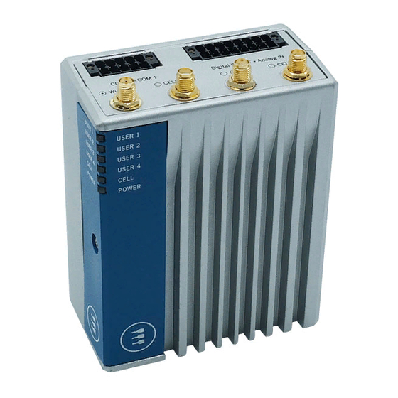
ReliaGATE 10-14 User manual Rev. 0-10 8 Interfaces overview NTERFACES OVERVIEW LED Indicators overview The LED Indicators are as follows: Figure 8.1 - LED Indicators layout Ref# Color USER1 (General Purpose) Green USER2 (General Purpose) Green USER3 (General Purpose) Amber USER4 (General Purpose) Amber CELL (Internal Cellular Modem activity;... -
Page 38: Top Side Interfaces Overview
8 Interfaces overview ReliaGATE 10-14 User manual Rev. 0-10 Top Side Interfaces overview The Top Side Interfaces are as follows: Figure 8.2 - Top Side Interfaces layout Ref# Description COM 0/1 connector Digital IN/OUT, Analog IN connector Antenna connector for 2.4 GHz/ 5 GHz Wi-Fi/ Bluetooth Main antenna connector for the Internal Cellular Modem (only for versions: -35, -36, -37) Antenna connector for the Internal GNSS (only for versions: -35, -36, -37) Diversity antenna connector for the Internal Cellular Modem (only for versions: -35, -36, -37) -
Page 39: Bottom Side Interfaces Overview
ReliaGATE 10-14 User manual Rev. 0-10 8 Interfaces overview Bottom Side Interfaces overview The Bottom Side Interfaces are as follows: Figure 8.3 - Bottom Side Interfaces layout Ref# Description Power IN connector DisplayPort USB0 connector USB1 connector Ethernet ETH0 connector Ethernet ETH1 connector Table 8.3 - Bottom Side Interfaces description 39 / 90... -
Page 40: Right Side Interfaces Overview
8 Interfaces overview ReliaGATE 10-14 User manual Rev. 0-10 Right Side Interfaces overview The Right Side Interface is as follows: Figure 8.4 - Right Side Interfaces layout Ref# Description Expansion connector Table 8.4 - Right Side Interfaces description For more information see: "Expansion"... -
Page 41: Service Panel Overview (Left Side)
ReliaGATE 10-14 User manual Rev. 0-10 8 Interfaces overview Service Panel overview (Left Side) The Service Panel is placed on the Left Side and includes the Service Interfaces. Ref# Description Service Panel: includes the Service Interfaces 8.5.1 Anti-Tamper Function The ReliaGATE 10-14 is equipped with anti-tamper detection: when the Service Panel (or the case) is opened, the intrusion event is timestamped and recorded by the RTC. -
Page 42: How To Remove The Service Panel Cover
8 Interfaces overview ReliaGATE 10-14 User manual Rev. 0-10 8.5.2 How to remove the Service Panel cover NOTICE The IP grade is not maintained when the Service Panel cover is removed. Do not use the product for extended periods of time with the Service Panel cover removed, otherwise dust and other particulates may enter the system. -
Page 43: Service Interfaces Overview
ReliaGATE 10-14 User manual Rev. 0-10 8 Interfaces overview 8.5.3 Service Interfaces overview The Interfaces available in the Service Panel are as follows: Figure 8.5 - Service Interfaces layout Ref# Description MicroSD push-push card holder DIP-switch for the Ignition Key control functionality DIP-switch for SD card/internal eMMC BOOT MiniSIM push-pull card holder 1 (top) MiniSIM push-pull card holder 2 (bottom) - Page 44 8 Interfaces overview ReliaGATE 10-14 User manual Rev. 0-10 8.5.3.1 DIP-switches meaning Default DIP switch configuration is OFF; this means no resistors inserted. The DIP-switches allow you to control the following functions: Function Description Ignition Key control functionality ON: Ignition Key control enabled OFF: Ignition Key monitoring only SD card/Internal eMMC BOOT ON: Boot enabled from SD card...
-
Page 45: Microsd And Minisim Card Holders
ReliaGATE 10-14 User manual Rev. 0-10 8 Interfaces overview 8.5.4 MicroSD and MiniSIM card holders Both the MicroSD card holder and the dual MiniSIM cards holder are placed on the top side of the circuit board in the Service Panel: The MicroSD card holder is a push-push type. -
Page 46: Rear Side Overview
8 Interfaces overview ReliaGATE 10-14 User manual Rev. 0-10 Rear Side overview The Rear Side is as follows: Figure 8.7 - Rear Side layout Ref# Description Product Label position DIN Rail Mounting Clip Earth connection terminal Table 8.6 - Rear Side description 46 / 90... -
Page 47: Interfaces In Detail
ReliaGATE 10-14 User manual Rev. 0-10 9 Interfaces in detail NTERFACES IN DETAIL Wi-Fi and Bluetooth The ReliaGATE 10-14 integrates a dual-band (2.4 & 5GHz), 1-stream (1x1) 802.11ac Wi-Fi and Bluetooth (BT/BLE4.2) module. The antenna connector is placed on the top side. 9.1.1 Wi-Fi and Bluetooth specifications Feature... -
Page 48: Internal Cellular Modem And Gnss (Vers: -35, -36, -37)
9 Interfaces in detail ReliaGATE 10-14 User manual Rev. 0-10 Internal Cellular Modem and GNSS (vers: -35, -36, -37) According to the product version, the ReliaGATE 10-14 can integrate the following cellular modem variants, with GNSS functionality: Product version Modem variant Technology Telit LE910C1-NF - North America LTE Cat 1 3G Fallback... -
Page 49: Second Cellular Antenna Requirements (For Antenna Diversity)
Single LTE antenna operation can be supported; however, typically, wireless carriers (Mobile Network Operators) impose restrictions. Please consult with your carrier before considering single LTE antenna usage. For optimum performance of the cellular interface, Eurotech recommends the use of both CELL MAIN and CELL DIV antenna connectors. 9.2.6... -
Page 50: Gnss Antenna - Installation Guidelines
9 Interfaces in detail ReliaGATE 10-14 User manual Rev. 0-10 9.2.7 GNSS antenna - Installation guidelines The antenna must not be co-located or operating in conjunction with any other antenna or transmitter. The antenna must not be installed inside metal cases. 9.2.8 GNSS antenna requirements The ReliaGATE 10-14 supports an active antenna. -
Page 51: Digital In/Out And Analog In
ReliaGATE 10-14 User manual Rev. 0-10 9 Interfaces in detail Digital IN/OUT and Analog IN The ReliaGATE 10-14 provides the following interfaces on the top side: 4x Digital Inputs Optoisolated, 2x Digital Outputs Optoisolated, 2x 11-bit Analog Inputs Isolated 9.3.1 Digital IN/OUT and Analog IN specifications Digital inputs specifications: Optoisolation 1.5kV... -
Page 52: Com0 And Com
9 Interfaces in detail ReliaGATE 10-14 User manual Rev. 0-10 COM0 and COM 1 The ReliaGATE 10-14 provides 2x RS-232/422/485 protected and isolated serial ports on the top side. 9.4.1 COM0 and COM 1 connector specifications Connector Layout: Connector Pinout in RS-232 mode: Pin # Port Signal... -
Page 53: Displayport
ReliaGATE 10-14 User manual Rev. 0-10 9 Interfaces in detail DisplayPort The ReliaGATE 10-14 provides a DisplayPort on the bottom side. 9.5.1 DisplayPort connector specifications Connector Layout: Connector Pinout: Pin # Signal Type Description Lane0P Lane 0 (positive) Ground Lane 0N Lane 0 (negative) Connector Specifications: Lane1P... -
Page 54: Usb 0 And Usb 1
9 Interfaces in detail ReliaGATE 10-14 User manual Rev. 0-10 USB 0 and USB 1 The ReliaGATE 10-14 provides 2x Host 2.0 USB ports (Noise and Surge Protected) for general purpose applications on the bottom side: USB 0; max load: 500 mA USB 1;... -
Page 55: Eth 0 And Eth
ReliaGATE 10-14 User manual Rev. 0-10 9 Interfaces in detail ETH 0 and ETH 1 The ReliaGATE 10-14 provides 2x 10/100/1000 Mbps Ethernet ports: ETH 0 ETH 1 The Ethernet connectors are available on the bottom side. 9.7.1 Ethernet specifications Feature Description Network Standard... -
Page 56: Expansion
9 Interfaces in detail ReliaGATE 10-14 User manual Rev. 0-10 Expansion The ReliaGATE 10-14 provides, on the right side, an expansion connector with the following interfaces: USB interface S Audio interface SPI interface Additional GPIO signals C interface For more information see: "Right Side Interfaces overview"... -
Page 57: Ttl Serial Console
ReliaGATE 10-14 User manual Rev. 0-10 9 Interfaces in detail TTL Serial Console The ReliaGATE 10-14 provides a 3.3 V TTL compatible Serial console in the Service Panel. The voltage levels are as follows: Logic 1 (Hi): 2.0 to 3.3 V Logic 0 (Low): 0 to 0.8 V 9.9.1 TTL Serial Console connector specifications... -
Page 58: Rtc (Real Time Clock)
9 Interfaces in detail ReliaGATE 10-14 User manual Rev. 0-10 9.11 RTC (Real Time Clock) The ReliaGATE 10-14 includes the following two RTC (Real Time Clocks) devices: RTC device Description /dev/rtc0 External (I2C-based RTC device) User available Default RTC used by Linux Accuracy: 25 minutes per year (at 25 °C) /dev/rtc1 Internal (in the CPU SoC) -
Page 59: The Software
10 The Software OFTWARE 10.1 The Linux OS Distribution Eurotech provides a Linux distribution based on a Yocto framework, www.yoctoproject.org, as well as an SDK for application development. For more information see: www.yoctoproject.org/documentation. 10.2 Ensure power supply during installation and update If the system only runs Linux: During installation and update, ensure a reliable source of power for the duration of the install process and for a period of 30 seconds after the first boot. -
Page 60: Partition Layout
10 The Software ReliaGATE 10-14 User manual Rev. 0-10 To disable the system firewall service, complete the following steps: 1. Enter the command systemctl disable iptables 2. Reboot the ReliaGATE 10-14 for the setting to take effect. NOTICE Running a system without a firewall is not recommended for production systems. 10.6 Partition layout The partition layout is as follows:... -
Page 61: How To Access The Administration Console
Default credentials By default the system provides two users: guest root The guest password is Eurotech and it provides non root privileges. The root password is set by default to the serial number of the device 11.2 Login Messages Messages can be displayed before and after attempts to access the ReliaGATE 10-14, either via the serial console or using ssh. -
Page 62: How To Login Via Secure Shell (Ssh)
"Default credentials" on the previous page). 11.5 How to change the password For security reasons, Eurotech recommends you change the password of the "root" account after your initial setup. To change the password, complete the following steps: 1. Login to the Administration Console 2. -
Page 63: How To Use The Interfaces In Linux
ReliaGATE 10-14 User manual Rev. 0-10 12 How to use the interfaces in Linux OW TO USE THE INTERFACES IN INUX Interface availability depends on product version. 12.1 General Purpose IO The ReliaGATE 10-14 offers a number of general purpose IO lines (GPIOs): some provide additional support for other interfaces such as expansion connector power supply control etc, while others provide functionality such as the opto-isolated IO channels, and user LEDs etc which are available for use in application programs. -
Page 64: How To Use The Gpios: The Gpio Utility
12 How to use the interfaces in Linux ReliaGATE 10-14 User manual Rev. 0-10 12.2 How to use the GPIOs: the GPIO Utility The ReliaGATE 10-14 includes the gpio_utility which provides a more convenient way to drive many of the GPIO functions from the command line: gpio_utility pin_name function pin_name It is the required GPIO line in the format gpioN or gpioBank_Pin. -
Page 65: How To Use The Digital I/Os
ReliaGATE 10-14 User manual Rev. 0-10 12 How to use the interfaces in Linux 12.4 How to use the Digital I/Os The ReliaGATE 10-14 includes 4 opto-isolated inputs and 2 opto-isolated outputs. These IOs are provided by GPIO lines which are available through the sysfs interface. The table below shows the GPIO line associated with each IO: IO Line # GPIO... -
Page 66: Analog Inputs
12 How to use the interfaces in Linux ReliaGATE 10-14 User manual Rev. 0-10 12.5 Analog Inputs The ReliaGATE 10-14 includes two analog-to-digital converters (ADCs) which are available for use in application programs. The two ADC inputs are isolated from the ReliaGATE 10-14 power supply but share a common ground with each other and with the serial ports. -
Page 67: How To Use The Serial Ports
How to configure the COM port mode The COM port mode can be configured in the following ways: From the command line (using the Eurotech ethsetserial utility) From an application program (using the Eurotech set serial mode API). 67 / 90... - Page 68 12 How to use the interfaces in Linux ReliaGATE 10-14 User manual Rev. 0-10 12.6.2.1 Configuring the COM port mode from the command line (using the Eurotech ethsetserial utility) The ethsetserial utility provides a simple was to configure a COM port mode from the command line or...
- Page 69 12 How to use the interfaces in Linux 12.6.2.2 Configuring the COM port mode from an application program (using the Eurotech set serial mode API) The SDK for the REGATE-10-14 includes a library that allows the mode of the serial port to be controlled directly from a C or C++ application.
- Page 70 12 How to use the interfaces in Linux ReliaGATE 10-14 User manual Rev. 0-10 const char * _eth_SerialModeName(int mode) mode: Integer representing the mode Returns a zero terminated string describing the given mode The example below set COM1 to RS-422 with terminators off then transmits ‘hello’: #include <stdio.h>...
-
Page 71: How To Use The Internal Cellular Modem
ReliaGATE 10-14 User manual Rev. 0-10 12 How to use the interfaces in Linux 12.7 How to use the Internal Cellular Modem The ReliaGATE 10-14 supports the Telit LE910C1family of LTE cellular modems: Product version Modem variant Technology Telit LE910C1-NF - North America LTE Cat 1 3G Fallback Telit LE910C1-EU - Europe LTE Cat 1 2G/3G Fallback... -
Page 72: How To Disable/Enable The Diversity (Cell Div) Function
12 How to use the interfaces in Linux ReliaGATE 10-14 User manual Rev. 0-10 12.7.2.1 How to select the AT&T firmware To select the AT&T firmware, use the following command: telit-he910 chat ‘AT#FWSWITCH=0,1’ 12.7.2.2 How to select the Verizon firmware To select the Verizon firmware, use the following command: telit-he910 chat ‘AT#FWSWITCH=1,1’... -
Page 73: 12.10 The Ignition Key
ReliaGATE 10-14 User manual Rev. 0-10 12 How to use the interfaces in Linux 12.10 The Ignition Key The ReliaGATE 10-14 includes an ignition monitoring circuit which can be used in battery-operated applications. Whilst the ignition input is low, the ReliaGATE 10-14 is powered OFF and will not drain the battery. The Ignition Key is a digital input that enables the product to be turned ON/OFF according to the following operating principle: A DIP-switch (SW# 1) in the Service Panel allows control the Ignition Key control functionality:... -
Page 74: Ignition Monitoring Service
12 How to use the interfaces in Linux ReliaGATE 10-14 User manual Rev. 0-10 12.10.1 Ignition monitoring service The ignition monitoring service calls a script when a change is detected. The default script, located in /usr/bin/ignition_script.sh, initiates a controlled shutdown but this can be changed as required. - Page 75 ReliaGATE 10-14 User manual Rev. 0-10 12 How to use the interfaces in Linux To disable the system service, enter the following commands: systemctl disable tampermon systemctl stop tampermon The service monitors the tamper detect and calls an action script each time a new event is detected. The action script is located in /usr/bin/tamper_script.sh The default script issues a warning message to all users but that can be modified to suite different situations.
-
Page 76: 12.12 How To Output Accelerometer And Gyroscope Values
12 How to use the interfaces in Linux ReliaGATE 10-14 User manual Rev. 0-10 12.12 How to output Accelerometer and Gyroscope values The ReliaGATE 10-14 includes a 3D digital accelerometer / 3D digital gyroscope: The accelerometer is exposed as cat/sys/bus/iio/devices/iio\:device2 The gyroscope is exposed as cat /sys/bus/iio/devices/iio\:device3 To output the three-dimensional values for the accelerometer, use the following commands: watch –n 1 cat /sys/bus/iio/devices/iio\:device2/in_accel_x_raw... -
Page 77: 12.15 How To Use The Watchdog
ReliaGATE 10-14 User manual Rev. 0-10 12 How to use the interfaces in Linux 12.15 How to use the Watchdog The ReliaGATE 10-14 uses the processor’s internal watchdog to reset the system if the software stops responding. Once triggered, the watchdog must be written to within a configurable timeout period to prevent the system reset. -
Page 78: 12.17 User-Programmable Pushbutton: Factory Restore
To view and set a specific restore mode, use the following command: eurotech_restore_mode To disable the factory restore functionality, use the following commands: eurotech_restore_mode 1 systemctl disable eurotech-restore 12.17.2 How to use the user-programmable pushbutton for other applications To use the user-programmable pushbutton for other applications, disable the factory restore functionality. -
Page 79: Mechanical Specifications
ReliaGATE 10-14 User manual Rev. 0-10 13 Mechanical specifications ECHANICAL SPECIFICATIONS 13.1 Product mechanical dimensions The product electronics are housed in an aluminum alloy enclosure having the following dimensions: 107 (L) x 85 (W) x 46 (H); mm - Antennas Connectors and Mounting Bracket excluded. All dimensions are in millimeters. - Page 80 (This page has been intentionally left blank)
-
Page 81: How To Install The Product
ReliaGATE 10-14 User manual Rev. 0-10 14 How to install the product OW TO INSTALL THE PRODUCT The product is intended for professional use and must be installed by qualified personnel only. The product must be installed in a secured location, accessible to authorized personnel only (for example in a cabinet / technical compartment). -
Page 82: How To Install The Product On A Din Rail
14 How to install the product ReliaGATE 10-14 User manual Rev. 0-10 14.1 How to install the product on a DIN Rail Prerequisite: Make sure that the DIN rail is placed horizontally. To install the product on a horizontal DIN rail, complete the following steps: 1. -
Page 83: 15 Power Supply. How To Turn On/Off And Reset The Product
ReliaGATE 10-14 User manual Rev. 0-10 15 Power supply. How to turn ON/OFF and reset the product ON/OFF OWER SUPPLY OW TO TURN AND RESET THE PRODUCT This product is not provided with any ON/OFF switch. The Power IN connector is the disconnecting means from the power supply network. 15.1 Power supply specifications Power Supply... -
Page 84: How To Supply Power And Turn On The Product
"Earth connection terminal" on page 57 8. Use a power supply that meets the product requirements and complies with the relevant standards and regulations. In case of uncertainties, contact the Eurotech Technical Support Team (for more information see "How to receive technical assistance" on page 17) -
Page 85: How To Turn Off The Product
ReliaGATE 10-14 User manual Rev. 0-10 15 Power supply. How to turn ON/OFF and reset the product 7. Connect Pin 3 (Key Signal) to "Power IN +". The ReliaGATE 10-14 automatically turns ON and the LED 6 (POWER) turns ON NOTICE When connecting Pin 3 to "Power IN +", keep it connected for at least 10 seconds. - Page 86 (This page has been intentionally left blank)
-
Page 87: How To Maintain The Product
ReliaGATE 10-14 User manual Rev. 0-10 16 How to maintain the product OW TO MAINTAIN THE PRODUCT Periodically inspect the product to verify its integrity and to ensure proper operation. To maintain the product, complete the following steps: 1. Carefully read and understand the instructions contained in the section "Safety instructions"... - Page 88 (This page has been intentionally left blank)
-
Page 89: Notes
ReliaGATE 10-14 User manual Rev. 0-10 Notes OTES 89 / 90... - Page 90 Via Fratelli Solari, 3/a For your Eurotech local contact refer to: eurotech.com/contacts 33020 Amaro (UD) - Italy Tel: +39 0433.485.411 For the Eurotech Global Support Centre refer to: support.eurotech.com Fax: +39 0433.485.499 Email: welcome@eurotech.com For the Eurotech Download Area refer to: eurotech.com/download...
Need help?
Do you have a question about the ReliaGATE 10-14 Series and is the answer not in the manual?
Questions and answers