
Related Manuals for Eurotech ReliaGATE 10-12-6 Series


Summary of Contents for Eurotech ReliaGATE 10-12-6 Series
- Page 1 User manual ReliaGATE 10-12-6x IoT Edge Gateway TI AM335x, LTE Cat 1 Rev. 2-1 — 16 October 2020 — REGATE-10-12-6x_Man_ENG_2-1 — ENGLISH...
-
Page 2: Trademarks
16 October 2020 9.8 "USB 0, USB 1, USB 2" 10 "The software" 11.1 "Default credentials" Added section: "Canadian Representative contact information" in chapter 7.4 © 2020 Eurotech SpA - Via Fratelli Solari 3/A - 33020 AMARO (UD) - Italy... -
Page 3: How To Get Started
For more information see: "Safety instructions" on page 9. Whenever in doubt regarding the correct understanding of this document, contact the Eurotech Technical Support. For more information see: "How to receive technical assistance" on page 17 2. - Page 4 (This page has been intentionally left blank)
-
Page 5: Table Of Contents
ReliaGATE 10-12 User manual Rev. 2-1 Contents ONTENTS Trademarks Intended audience of this document Revision history How to get started Contents 1 Safety instructions 1.1 Warning messages 1.1.1 Warning messages for harm to persons 1.1.2 Warning messages for damage to property 1.2 Warning: power supply safety 1.3 Caution: wireless safety 1.4 Warning: battery safety... - Page 6 Contents ReliaGATE 10-12 User manual Rev. 2-1 7.4 FCC/ISED Regulatory Notices 7.4.1 FCC marking 7.4.2 FCC Class B Digital Device Notice 7.4.3 FCC restrictions on 5 GHz Wi-Fi usage 7.4.4 ISED Canada Regulatory Notices 7.4.5 ISED Class B Digital Device Notice 7.4.6 Responsible parties: Canadian Representative contact information 7.4.7 RF Radiation Exposure Statement 7.4.8 Labeling Information...
- Page 7 ReliaGATE 10-12 User manual Rev. 2-1 Contents 9.10.1 TTL Serial Console connector specifications 9.11 MicroSD card holder 9.11.1 How to insert / remove the MicroSD card in the holder 9.12 RTC (Real Time Clock) 9.12.1 The RTC Device "/dev/rtc1" 9.12.2 The RTC backup battery 9.13 Watchdog 9.14 Accelerometer and Gyroscope 9.15 Programmable pushbutton...
- Page 8 13 How to compile custom software 13.1 How to setup the toolchain 13.2 How to use the toolchain to compile custom software 14 Eurotech Everyware IoT 14.1 Everyware Software Framework (ESF) 14.2 The ESF Web UI 14.3 The ESF Wires application 14.4 Everyware Cloud (EC)
-
Page 9: Safety Instructions
Failure to comply with the instructions and warnings contained in this document, violates the standards of safety, design, manufacture, and intended use of the product. Eurotech assume no liability for any damage caused by failure to observe the instructions and warnings contained in this document. -
Page 10: Warning Messages For Damage To Property
7. Make sure that the product maintains a proper grounding connection 8. Use a power supply that meets the product requirements and complies with the relevant standards and regulations. In case of uncertainties, contact the Eurotech Technical Support (for more information see "How to receive technical assistance"... -
Page 11: Warning: Battery Safety
ReliaGATE 10-12 User manual Rev. 2-1 1 Safety instructions Warning: battery safety WARNING SERIOUS HARM IF BATTERY IS USED INCORRECTLY Before using the battery always refer to battery manufacturer's instructions for safety. CAUTION RISK OF EXPLOSION IF BATTERY IS REPLACED BY AN INCORRECT TYPE Use and replace only with correct size and type. - Page 12 (This page has been intentionally left blank)
-
Page 13: Consignes De Securite
Eurotech rejette toute responsabilité pour les dommages causés en cas de non-respect des instructions et des avertissements contenus dans ce document. En cas de doute sur la compréhension de ce document, contacter le Support Technique d’ Eurotech (pour plus d’informations voir "Comment obtenir une assistance technique"... -
Page 14: Messages D'avertissement Relatifs Aux Dommages Matériels
7. S'assurer que le produit est correctement relié à la terre 8. Utiliser une alimentation électrique conforme aux exigences du produit et conforme aux normes et réglementations en vigueur. En cas d'incertitude, contacter l'équipe d'assistance technique d'Eurotech (pour plus d'informations, voir "Comment obtenir une assistance technique" page 9. -
Page 15: Avertissement: Sécurité De La Batterie
ReliaGATE 10-12 User manual Rev. 2-1 2 Consignes de securite Avertissement: Sécurité de la Batterie AVERTISSEMENT BLESSURES GRAVES SI LA BATTERIE EST UTILISÉE DE MANIÈRE INCORRECTE Avant d’utiliser la batterie, reportez-vous toujours aux instructions du fabricant de la batterie pour plus de sécurité. ATTENTION RISQUE D’EXPLOSION SI LA BATTERIE DE REMPLACEMENT NE RESPECTE PAS LES CARACTÉRISTIQUES DE LA BATTERIE INITIALE. - Page 16 (This page has been intentionally left blank)
-
Page 17: How To Receive Technical Assistance
3. Wait for the reply from the Eurotech Technical Support with the information you required How to send a product for repair Any product returned to Eurotech, that is found to be damaged due to inadequate packaging, will not be covered by the warranty. - Page 18 (This page has been intentionally left blank)
-
Page 19: Comment Obtenir Une Assistance Technique
3. Attendre la réponse de l'équipe de support avec les informations requises Comment retourner un produit en service après vente Tout produit renvoyé à Eurotech, qui se trouve endommagé en raison d'un emballage inadéquat, ne sera pas couvert par la garantie. - Page 20 (This page has been intentionally left blank)
-
Page 21: Conventions Used
Negative signal; Negative signal in differential pair 3.3 V signal level 5 V signal level No Connection Reserved Use is reserved to Eurotech Conventions for signal types Convention Description Signal is an input to the system Signal is an output from the system... - Page 22 (This page has been intentionally left blank)
-
Page 23: Product Overview
Distributed and supported by Eurotech, ESF supports ready-to-use field protocols (including Modbus, OPC-UA, S7), MQTT connectivity, web-based visual data flow programming and deep configuration. ESF is also integrated with Everyware Cloud (EC), Eurotech IoT Integration Platform (separately available), enabling advanced diagnostics, provisioning, and full remote device access and management. -
Page 24: Intended Use And Not Allowed Uses Of The Product
6 Product overview ReliaGATE 10-12 User manual Rev. 2-1 Intended use and not allowed uses of the product The product is intended for professional use and must be installed by qualified personnel only. The product must be installed in a secured location, accessible to authorized personnel only (for example in a cabinet / technical compartment). -
Page 25: Technical Specifications
ReliaGATE 10-12 User manual Rev. 2-1 6 Product overview Technical specifications The ReliaGATE 10-12 family is available in several -XY versions, for example: ReliaGATE 10-12-63 (where: X = 6, Y = 3). The specifications are the following, according to the respective versions: Specifications Description according to -XY versions -65/ -65G... - Page 26 6 Product overview ReliaGATE 10-12 User manual Rev. 2-1 Specifications Description according to -XY versions -65/ -65G -66/ -66G -67/ -67G Power Input Nominal: 12 or 24 VDC; Range: 9 to 30 VDC with transient protection Consumption 2 W idle; 15 W maximum Environment Operating -40 to +70°C...
-
Page 27: Optional Accessories
ReliaGATE 10-12 User manual Rev. 2-1 6 Product overview Optional accessories To simplify the development of applications, you can request the following optional accessories: Accessory Order Code Accessory Description MEC-40200-00 DIN Rail Mounting Kit, composed of: 1x DIN Rail Mounting Clip 3x Phillips Countersunk Screws E16-50-11-00 Power Supply 24W;... - Page 28 6 Product overview ReliaGATE 10-12 User manual Rev. 2-1 Notes about the antennas Depending to in-field applications, Eurotech recommends the following antennas: Wi-Fi/BT Mounting type Order Code Example Telematic-mount E29-10-11-00 Magnetic/Adhesive-mount 99ACC-60750-C0007 Cellular: Mounting type Order Code Example Telematic-mount 99ACC-60750-C0004...
-
Page 29: Product Labels
The following labels are placed on the product: Label example Label type and content Label position Part Number Label On the underside of Eurotech logo the product Manufacturer name Manufacturer address (EU versions only) Product number Model number (xx = product version) - Page 30 (This page has been intentionally left blank)
-
Page 31: Regulatory Information
They comply with the regulatory information reported in the following sections. Eurotech is not responsible for the use of this product together with equipment (for example: power supplies, personal computers, etc.) that are not CE marked and not compliant with the requirements specified in this document. -
Page 32: Rohs 3 Compliance
"Technical specifications" on page 25. Modification statement Eurotech has not approved any changes or modifications to this product by the user. Any changes or modifications could void the user’s authority to operate this product. 7.1.6.1 EU restrictions on 5 GHz Wi-Fi usage... -
Page 33: Statement For Class A Equipment (Vers.: -61)
ReliaGATE 10-12 User manual Rev. 2-1 7 Regulatory information 7.1.6.2 Class II product According to Commission Decision 2000/299/EC of 6 April 2000, establishing the initial classification of radio equipment and telecommunications terminal equipment and associated identifiers, the product falls within the scope of Class II. Due to EU restrictions on 5 GHz Wi-Fi bands the product is limited to indoor operation and should only be operated in the frequency band 5150 MHz –... -
Page 34: Fcc/Ised Regulatory Notices
They comply with the regulatory information reported in the following sections. Eurotech is not responsible for the use of the product together with equipment (for example: power supplies, personal computers, etc.) that are not FCC marked and not compliant with the requirements specified in this document. -
Page 35: Fcc Restrictions On 5 Ghz Wi-Fi Usage
ReliaGATE 10-12 User manual Rev. 2-1 7 Regulatory information Réorienter ou déplacer l'antenne de réception Augmenter la distance entre le produit et le récepteur Brancher l'appareil sur une prise de courant différente de celle à laquelle le récepteur est raccordé Consulter le revendeur ou un technicien radio/TV expérimenté... -
Page 36: Ised Canada Regulatory Notices
7 Regulatory information ReliaGATE 10-12 User manual Rev. 2-1 7.4.4 ISED Canada Regulatory Notices This device contains licence-exempt transmitter(s)/receiver(s) that comply with Innovation, Science and Economic Development Canada’s licence-exempt RSS(s). Operation is subject to the following two conditions: (1) this device may not cause harmful interference, and (2) this device must accept any interference received, including interference that may cause undesired operation. -
Page 37: Rf Radiation Exposure Statement
ReliaGATE 10-12 User manual Rev. 2-1 7 Regulatory information 7.4.7 RF Radiation Exposure Statement This product complies with FCC and ISED radiation exposure limits set forth for an uncontrolled environment. The antenna should be installed and operated with minimum distance of 20 cm between the radiator and your body. -
Page 38: Reach Compliance
This product has been assessed to be compliant with the regulation (EC) No. 1907/2006 (REACH) (with the exceptions allowed by the EU Technical Committee). Eurotech has set in place a monitoring process to assess compliance to REACH regulation. For details and more information contact the Eurotech Technical Support (see "How to receive technical... -
Page 39: Interfaces Overview
ReliaGATE 10-12 User manual Rev. 2-1 8 Interfaces overview NTERFACES OVERVIEW Front Side Interfaces overview The Front Side Interfaces are as follows: Figure 8.1 - Front Side Interfaces layout Ref# Description Antenna connector for 2.4 GHz Wi-Fi / Bluetooth (all vers. except: -61, -63, -64) Main antenna connector for Internal Cellular Modem: CELL MAIN (all vers. -
Page 40: Rear Side Interfaces Overview
8 Interfaces overview ReliaGATE 10-12 User manual Rev. 2-1 Rear Side Interfaces overview The Rear Side Interfaces are as follows: Figure 8.2 - Rear Side Interfaces layout Ref# Description Ethernet ETH 1 connector Ethernet ETH 0 connector USB 0 connector USB 1 connector Service Panel Power IN connector... -
Page 41: Service Panel Interfaces
ReliaGATE 10-12 User manual Rev. 2-1 8 Interfaces overview 8.2.1 Service Panel Interfaces The Interfaces available in the Service Panel are as follows: Figure 8.3 - Service Interfaces layout Ref# Description Combo MicroSD (push-pull) + MicroSIM (pull-lever) cards holder RTC battery connection jumper Boot selection jumper DIP-switch for serial ports configuration Programmable pushbutton... -
Page 42: Right Side Interface Overview
8 Interfaces overview ReliaGATE 10-12 User manual Rev. 2-1 Right Side Interface overview The Right Side Interface is as follows: Figure 8.4 - Right Side Interfaces layout Ref# Description Expansion connector Table 8.4 - Right Side Interfaces description For more information see: "Expansion connector"... -
Page 43: Left Side Interface Overview
ReliaGATE 10-12 User manual Rev. 2-1 8 Interfaces overview Left Side Interface overview The Left Side Interface is as follows: Figure 8.5 - Left Side Interface layout Ref# Description 2.0 Host USB connector (ready to interface optional USB accessories, e.g.: ReliaCELL 10-20) Table 8.5 - Left Side Interface description 43 / 118... -
Page 44: Led Indicators Overview
8 Interfaces overview ReliaGATE 10-12 User manual Rev. 2-1 LED Indicators overview The LED Indicators are as follows: Figure 8.6 - LED Indicators layout Ref# Color USER1 (General Purpose) Green USER2 (General Purpose) Green USER3 (General Purpose) Amber USER4 (General Purpose) Amber CELLULAR (Internal Cellular Modem activity;... -
Page 45: Interfaces In Detail
ReliaGATE 10-12 User manual Rev. 2-1 9 Interfaces in detail NTERFACES IN DETAIL Wi-Fi and Bluetooth (all vers. except: -61, -63, -64) The ReliaGATE 10-12 provides the following Wi-Fi / Bluetooth function: 2.4 GHz Wi-Fi 802.11a,b,g,n / BLE 4.2 BLE Bluetooth 5 GHz Wi-Fi 802.11a,b,g,n The internal circuitry allows for 2.4 GHz Wi-Fi and Bluetooth coexistence. -
Page 46: Bluetooth Specifications
9 Interfaces in detail ReliaGATE 10-12 User manual Rev. 2-1 9.1.2 Bluetooth specifications Supports Bluetooth 4.2 Includes concurrent operation and built -in coexisting and prioritization handling of Bluetooth, BLE, audio processing and WLAN Dedicated Audio processor supporting on chip SBC encoding + A2DP: Assisted A2DP (A3DP) support - SBC encoding implemented internally Assisted WB-Speech (AWBS) support - modified SBC codec implemented internally 9.1.3... -
Page 47: Internal Cellular Modem (All Vers. Except: -61, -62)
Operators) impose restrictions. Please consult with your carrier before considering single LTE antenna usage. For optimum performance of the cellular interface, Eurotech recommends the use of both CELL MAIN and CELL DIV antenna connectors. If CELL DIV antenna is not used/connected, Eurotech recommends to disable the diversity function: see "How to disable/enable the diversity (CELL DIV) function"... - Page 48 9 Interfaces in detail ReliaGATE 10-12 User manual Rev. 2-1 9.2.2.1 Main antenna requirements Telit LE910-NA1 - North America version Feature Value Frequency range Depending by the frequency band(s) provided by the network operator Bands "Supported RF bands" on the previous page Impedance 50 Ohm Input power...
- Page 49 ReliaGATE 10-12 User manual Rev. 2-1 9 Interfaces in detail 9.2.2.2 Second antenna requirements (for antenna diversity) Telit LE910-NA1 - North America version Feature Value Frequency range Depending by the frequency band(s) provided by the network operator Impedance 50 Ohm VSWR recommended ≤...
-
Page 50: Antennas Connectors Specifications
9 Interfaces in detail ReliaGATE 10-12 User manual Rev. 2-1 9.2.3 Antennas connectors specifications Specifications are the same for both the following connectors: Main Antenna Connector Diversity Antenna Connector Connector Layout: Connector Pinout: Pin # Description Female inner pin contact Female connector body (outer thread) Connector Specifications: SMA connector... -
Page 51: The Microsim Card Holders
ReliaGATE 10-12 User manual Rev. 2-1 9 Interfaces in detail 9.2.4 The MicroSIM card holders The ReliaGATE 10-12 includes the following MicroSIM card holders: 1st MicroSIM card holder: Integrated in a Combo MicroSD (push-pull) + MicroSIM (pull-lever) cards holder Placed on the top side of the circuit board in the Service Panel 2nd MicroSIM card holder: Push-pull card holder... - Page 52 9 Interfaces in detail ReliaGATE 10-12 User manual Rev. 2-1 If you are using the holder on the bottom side of the circuit board To insert the MicroSIM card, complete the following steps: 1. Orient the MicroSIM card with the contacts facing the circuit board and the cut corner - highlighted with the letter - facing the holder 2.
-
Page 53: Internal Gnss (Vers.: -65G, -66G, -67G)
ReliaGATE 10-12 User manual Rev. 2-1 9 Interfaces in detail Internal GNSS (vers.: -65G, -66G, -67G) The ReliaGATE 10-12 provides the following GNSS function: Internal Untethered Dead Reckoning; 72 channels GPS, Galileo, GLONASS, BeiDou. The GNSS outputs NMEA data; this data can be read by applications directly. The antenna connector is placed on the front side. -
Page 54: Digital I/Os
9 Interfaces in detail ReliaGATE 10-12 User manual Rev. 2-1 Digital I/Os The ReliaGATE 10-12 provides the following Digital I/Os: 2x Digital Input: 36 V, 1 kV Optoinsulated 2x Digital Output: 40 V AC/DC, 1 kV Optoinsulated, 500 mA, 1 kHz Max Switching The Digital I/Os connector is available on the front side. -
Page 55: Insulated Digital Outputs
ReliaGATE 10-12 User manual Rev. 2-1 9 Interfaces in detail 9.4.2 Insulated Digital Outputs 9.4.2.1 Electrical specifications The table below shows the electrical specifications of the digital outputs: Characteristic Value Maximum Voltage 40 V Maximum Current 500 mA Output ON Resistance Typical: 0.83 Ohm Maximum: 2.50 Ohm Maximum switching frequency... -
Page 56: Com 0 And Com 1
9 Interfaces in detail ReliaGATE 10-12 User manual Rev. 2-1 COM 0 and COM 1 The ReliaGATE 10-12 provides the following COM ports: 1x RS-422/485: COM 0; Surge protected, Insulated, Full Duplex/Half Duplex (Default: RS-485 Full Duplex) 1x RS-232/485: COM 1; Surge protected, RS-485 termination and fail-safe resistors (Default: RS-232) COM ports specifications: The COM ports are surge protected... -
Page 57: Note For Fail-Safe Resistors For Com 1 In Rs-485 Mode
ReliaGATE 10-12 User manual Rev. 2-1 9 Interfaces in detail 9.5.4 Note for fail-safe resistors for COM 1 in RS-485 mode To insert the RS-485 fail-safe resistors, use the DIP switch available in the Service Panel. 9.5.4.1 Switches meaning Default DIP switch configuration is OFF; this means no resistors inserted. SW # Signal Description... -
Page 58: Com 0 And Com 1 Connector Specifications
9 Interfaces in detail ReliaGATE 10-12 User manual Rev. 2-1 9.5.6 COM 0 and COM 1 connector specifications Connector Layout: Connector Pinout: Pin # Signal Type Description COM 0: Y/D+ COM port 0: RS-422: TX+ (Y) RS-485: A (D+ Line) Connector Specifications: COM 0: Z/D- COM port 0:... -
Page 59: Can 0 And Can
ReliaGATE 10-12 User manual Rev. 2-1 9 Interfaces in detail CAN 0 and CAN 1 The ReliaGATE 10-12 provides 2x CAN (Controller Area Network) ports compliant with the CAN Specification 2.0, Parts A and B: CAN 0 CAN 1 The CAN connectors are available on the front side. For more information see: "How to manage the CAN ports"... -
Page 60: Eth 0 And Eth
9 Interfaces in detail ReliaGATE 10-12 User manual Rev. 2-1 ETH 0 and ETH 1 The ReliaGATE 10-12 provides 2x 10/100 Mbps Ethernet ports: ETH 0 ETH 1 The Ethernet connectors are available on the rear side. For more information see: "How the Ethernet ports are exposed"... -
Page 61: Usb 0 And Usb 1 Connectors Specifications
ReliaGATE 10-12 User manual Rev. 2-1 9 Interfaces in detail USB 0, USB 1, USB 2 The ReliaGATE 10-12 provides 3x Host 2.0 USB ports (Noise and Surge Protected) for general purpose applications: USB 0 on the rear side USB 1 on the rear side USB 2 on the left side (ready to interface optional USB accessories, e.g.: ReliaCELL 10-20). -
Page 62: Expansion Connector
9 Interfaces in detail ReliaGATE 10-12 User manual Rev. 2-1 Expansion connector The ReliaGATE 10-12 provides, on the right side, an expansion connector with the following interfaces: Additional USB OTG interface S Audio interface GPIO expansion interface C interface SPI interface For more information see: "Right Side Interface overview"... -
Page 63: Ttl Serial Console
ReliaGATE 10-12 User manual Rev. 2-1 9 Interfaces in detail 9.10 TTL Serial Console The ReliaGATE 10-12 provides a 3.3 V TTL compatible Serial console in the Service Panel. The voltage levels are as follows: Log 1 (Hi): 2.0 to 3.3 V Log 0 (Low): 0 to 0.8 V For more information see: "How the TTL Serial Console is exposed"... -
Page 64: Microsd Card Holder
9 Interfaces in detail ReliaGATE 10-12 User manual Rev. 2-1 9.11 MicroSD card holder The MicroSD card holder is integrated in a Combo MicroSD (push-pull) + MicroSIM (pull-lever) cards holder, placed on the top side of the circuit board in the Service Panel. The holder allows you to insert a MicroSD card (up to 32 GB) for additional data storage. -
Page 65: Rtc (Real Time Clock)
ReliaGATE 10-12 User manual Rev. 2-1 9 Interfaces in detail 9.12 RTC (Real Time Clock) The ReliaGATE 10-12 includes the following two RTC (Real Time Clocks) devices: RTC device Description /dev/rtc0 Internal (in the CPU SoC) Reserved /dev/rtc1 External (I2C-based RTC device) User available Default RTC used by Linux Accuracy: 25 minutes per year (at 25 °C) -
Page 66: Watchdog
9 Interfaces in detail ReliaGATE 10-12 User manual Rev. 2-1 9.12.2.2 How to enable/disable the battery To enable/disable the battery, use the RTC battery jumper: Jumper inserted = Battery connected Jumper removed = Battery not connected 9.13 Watchdog The ReliaGATE 10-12 includes a watchdog / supervisor IC, external to the CPU. For more information see: "How the Watchdog is exposed"... -
Page 67: The Software
10 The Software OFTWARE 10.1 The Linux OS distribution Eurotech provides a Linux distribution based on a Yocto framework, www.yoctoproject.org, as well as an SDK for application development. All the documentation for the developer is available from:www.yoctoproject.org/documentation. 10.2 The bootloader procedure... -
Page 68: The Tpm
10 The Software ReliaGATE 10-12 User manual Rev. 2-1 10.5 The TPM The ReliaGATE 10-12 includes a TPM 2.0 hardware module: Infineon SLB9670. This is connected to the CPU via an SPI interface. By default, the ReliaGATE 10-12 does not utilise the TPM device. It is therefore fully available for customer use. -
Page 69: How To Login The Administration Console
By default the system provides two users: guest root The guest password is Eurotech and it provides non root privileges. The root password is set by default to the serial number of the device 11.2 How to login using the Serial Console To login using the Serial Console, complete the following steps: 1. -
Page 70: How To Login Via Eth0
"Default credentials" on the previous page). 11.4 How to change the password For security reasons, Eurotech recommends you to change the password of the "root" account after your initial setup. To change the password, complete the following steps: 1. Login the Administration Console 2. -
Page 71: How To Manage Interfaces In Linux
ReliaGATE 10-12 User manual Rev. 2-1 12 How to manage interfaces in Linux OW TO MANAGE INTERFACES IN INUX Interfaces availability depends on product version. If Everyware Software Framework (ESF) is installed, it will manage the network interfaces, cellular modem, Bluetooth adapter and GPIOs. Any changes you make to the Linux configuration files may be overwritten if the related service is managed by ESF. -
Page 72: How To Determine The Version Of Linux Installed
12 How to manage interfaces in Linux ReliaGATE 10-12 User manual Rev. 2-1 12.2 How to determine the version of Linux installed To determine the version of Linux installed, enter the following command: eurotech_versions Example output: eth_name_bsp: xxx eth_vers_bsp: Operating System version eth_partno_bsp: unknown eth_serial_number: xxx eth_model: xxx... -
Page 73: How To Manage The Internal Cellular Modem
ReliaGATE 10-12 User manual Rev. 2-1 12 How to manage interfaces in Linux 12.5 How to manage the Internal Cellular Modem The ReliaGATE 10-12 supports the following Telit LE910 modem variants, according to product versions based on the geographic area of usage: Product version Modem variant Technology... -
Page 74: How To Disable/Enable The Diversity (Cell Div) Function
12 How to manage interfaces in Linux ReliaGATE 10-12 User manual Rev. 2-1 12.5.2.1 How to select the AT&T firmware To select the AT&T firmware, use the following command: telit-he910 chat ‘AT#FWSWITCH=0,1’ 12.5.2.2 How to select the Verizon firmware To select the Verizon firmware, use the following command: telit-he910 chat ‘AT#FWSWITCH=1,1’... -
Page 75: How To Manage The Internal Gnss
ReliaGATE 10-12 User manual Rev. 2-1 12 How to manage interfaces in Linux 12.6 How to manage the Internal GNSS The ReliaGATE 10-12 exposes the GNSS as follows: /dev/ttyS5 You need to enable the GNSS before it will work. To enable the GNSS, enter the following command: gpio_utility gpio81 1 To prove that the positioning is working, dump the serial port output by entering the following commands:... -
Page 76: How To Manage The Can Ports
12 How to manage interfaces in Linux ReliaGATE 10-12 User manual Rev. 2-1 12.7 How to manage the CAN ports The ReliaGATE 10-12 exposes the CAN ports as follows: CAN 0 port: can0 CAN 1 port: can1 CAN ports are added through the SocketCAN kernel extension. For more information on SocketCAN refer to the Linux kernel documentation: www.kernel.org/doc/Documentation/networking/can.txt 12.7.1... -
Page 77: How To Manage The Com Ports
ReliaGATE 10-12 User manual Rev. 2-1 12 How to manage interfaces in Linux 12.9 How to manage the COM ports The ReliaGATE 10-12 exposes the COM ports as follows: COM port 0 (RS-422/485): /dev/ttyO4 (available on the front side) COM port 1 (RS-232/485): /dev/ttyO3 (available on the front side) You need to configure the serial ports mode before they will work. - Page 78 12 How to manage interfaces in Linux ReliaGATE 10-12 User manual Rev. 2-1 12.9.2.2 How to implement the ioctl in the source code to configure the COM ports To implement the ioctl in the source code, enter the following commands: /*Ioctl to read */ #define TIOCGRS485 0x542E...
- Page 79 ReliaGATE 10-12 User manual Rev. 2-1 12 How to manage interfaces in Linux Example: Configuring COM 0 in RS-422 mode ser_port_name has to be /dev/ttyO4 struct serial_rs485 rs485conf; unsigned int rs_mode_mask=(SER_HIZ_ENABLED|SER_RS485_ENABLED|SER_RS485_ INVERT|SER_RS485_RTS_ON_SEND|SER_RS485_RTS_AFTER_SEND); unsigned int set_flags=0; unsigned int set_flags_mask=rs_mode_mask; int fd; fd=open(ser_port_name,O_RDWR);...
- Page 80 12 How to manage interfaces in Linux ReliaGATE 10-12 User manual Rev. 2-1 Example: Configuring COM 0 in RS-485 mode ser_port_name has to be /dev/ttyO4 struct serial_rs485 rs485conf; unsigned int rs_mode_mask=(SER_HIZ_ENABLED|SER_RS485_ENABLED|SER_RS485_ INVERT|SER_RS485_RTS_ON_SEND|SER_RS485_RTS_AFTER_SEND); unsigned int set_flags=(SER_RS485_INVERT|SER_RS485_ENABLED|SER_RS485_RTS_ON_ SEND); unsigned int set_flags_mask=rs_mode_mask; int fd; fd=open(ser_port_name,O_RDWR);...
-
Page 81: How To Set The Rs-232/485 Modes For Com 1
ReliaGATE 10-12 User manual Rev. 2-1 12 How to manage interfaces in Linux 12.9.3 How to set the RS-232/485 modes for COM 1 You can configure the serial port mode in the following ways, A or B: A. Using the ethsetserial utility B. - Page 82 12 How to manage interfaces in Linux ReliaGATE 10-12 User manual Rev. 2-1 12.9.3.2 How to implement the ioctl in the source code to configure the COM ports To implement the ioctl in the source code, enter the following commands: /*Ioctl to read */ #define TIOCGRS485 0x542E...
- Page 83 ReliaGATE 10-12 User manual Rev. 2-1 12 How to manage interfaces in Linux Example: Configuring COM 1 in RS-232 mode ser_port_name has to be /dev/ttyO3 struct serial_rs485 rs485conf; unsigned int rs_mode_mask=(SER_HIZ_ENABLED|SER_RS485_ENABLED|SER_RS485_ INVERT|SER_RS485_RTS_ON_SEND|SER_RS485_RTS_AFTER_SEND); unsigned int set_flags=0; unsigned int set_flags_mask=rs_mode_mask; int fd; fd=open(ser_port_name,O_RDWR);...
-
Page 84: How To Test A Serial Port
12 How to manage interfaces in Linux ReliaGATE 10-12 User manual Rev. 2-1 Example: Configuring COM 1 in RS-485 mode ser_port_name has to be /dev/ttyO3 struct serial_rs485 rs485conf; unsigned int rs_mode_mask=(SER_HIZ_ENABLED|SER_RS485_ENABLED|SER_RS485_ INVERT|SER_RS485_RTS_ON_SEND|SER_RS485_RTS_AFTER_SEND); unsigned int set_flags=(SER_RS485_INVERT|SER_RS485_ENABLED|SER_RS485_RTS_ON_ SEND); unsigned int set_flags_mask=rs_mode_mask; int fd; fd=open(ser_port_name,O_RDWR);... -
Page 85: 12.10 How To Manage The Digital I/Os
ReliaGATE 10-12 User manual Rev. 2-1 12 How to manage interfaces in Linux 12.10 How to manage the Digital I/Os The ReliaGATE 10-12 exposes the Digital I/Os (GPIOs) as follows: Digital Input 1: /sys/class/gpio/gpio26/value Digital Input 2: /sys/class/gpio/gpio27/value Digital Output 1: /sys/class/gpio/gpio87/value Digital Output 2: /sys/class/gpio/gpio89/value... -
Page 86: How To Enable The 3.3V And 5V Power Supply On The Expansion Connector
12 How to manage interfaces in Linux ReliaGATE 10-12 User manual Rev. 2-1 12.13 How to enable the 3.3V and 5V power supply on the Expansion connector 3.3V and 5V are OFF by default and are controlled driving specific GPIO’s. To control the 3.3V, enter the following commands: #turn on 3.3V gpio_utility gpio71 1... -
Page 87: 12.14 How The Rtc Is Exposed
ReliaGATE 10-12 User manual Rev. 2-1 12 How to manage interfaces in Linux 12.14 How the RTC is exposed The ReliaGATE 10-12 exposes the RTC as follows: RTC: /dev/rtc1 /dev/rtc1 offers three read-only timestamp registers: Timestamp register What it contains sys/class/rtc/rtc1/device/timestamp1 Reserved data sys/class/rtc/rtc1/device/timestamp2... -
Page 88: 12.15 How The Watchdog Is Exposed
12 How to manage interfaces in Linux ReliaGATE 10-12 User manual Rev. 2-1 12.15 How the Watchdog is exposed The ReliaGATE 10-12 exposes the watchdog as follows: Watchdog: /dev/watchdog1 12.15.1 How to manage the Watchdog using the C programming language To manage the watchdog using the C programming language enter the following commands: Int interval;... -
Page 89: 12.16 How To Output Accelerometer And Gyroscope Values
ReliaGATE 10-12 User manual Rev. 2-1 12 How to manage interfaces in Linux 12.16 How to output Accelerometer and Gyroscope values The ReliaGATE 10-12 includes a 3D digital accelerometer / 3D digital gyroscope: The accelerometer is exposed as cat /sys/bus/iio/devices/iio\:device1 The gyroscope is exposed as cat /sys/bus/iio/devices/iio\:device0 To output the three-dimensional values for the accelerometer, use the following commands: watch -n 1 cat /sys/bus/iio/devices/iio\:device1/in_anglvel_x_raw... -
Page 90: 12.17 How To Read The Internal Temperature Sensor
12 How to manage interfaces in Linux ReliaGATE 10-12 User manual Rev. 2-1 12.17 How to read the Internal Temperature Sensor The ReliaGATE 10-12 is provided with a sensor that measures the temperature inside the product. To read the internal temperature, enter the following command: cat /sys/class/hwmon/hwmon0/temp1_input 12.18 How to know the programmable pushbutton status The programmable pushbutton can be programmed to execute a shell script every time the button is... -
Page 91: How To Compile Custom Software
1. Make sure you're using the correct toolchain version corresponding to the Yocto image installed on your gateway. The latest toolchain and Yocto image for your ReliaGATE 10-12 are available here: https://eurotech.github.io/linux-releases/ 2. Download the binary file (x86_64 version tested) on a Virtual/physical machine running Ubuntu (14.04 tested), execute it and select appropriate installation options 3. - Page 92 (This page has been intentionally left blank)
-
Page 93: Eurotech Everyware Iot
ESF allows the connection and communication with field devices (close to data sources), thanks to already tested libraries for field protocol communication, the visual IoT Edge Computing applications development and the connection with leading IoT Cloud Services such as Everyware Cloud (Eurotech IoT Integration Platform) , Eclipse Kapua, AWS IoT and Microsoft Azure IoT. -
Page 94: The Esf Web Ui
14 Eurotech Everyware IoT ReliaGATE 10-12 User manual Rev. 2-1 14.2 The ESF Web UI ESF provides a web-based user interface: ESF Web UI. The ESF Web UI provides several functions such as: Monitor the gateway status Manage the network configuration Oversee the installed application(s) and services. -
Page 95: The Esf Wires Application
ReliaGATE 10-12 User manual Rev. 2-1 14 Eurotech Everyware IoT 14.3 The ESF Wires application ESF provides also a dataflow programming model: Wires. Wires simplifies the development of Edge Computing Applications leveraging reusable configurable components. In the dataflow programming model, the application logic is expressed as a directed graph (flow) where each node can have inputs, outputs and independent processing units. -
Page 96: Everyware Cloud (Ec)
14.4 Everyware Cloud (EC) Eurotech’s Everyware™ Cloud (EC) is an IoT Integration Platform that simplifies system and data management by connecting distributed devices over secure and reliable cloud services. Everyware Cloud allows you to connect, configure and manage devices through all the lifecycle, from deployment through maintenance to retirement. -
Page 97: Mechanical Specifications
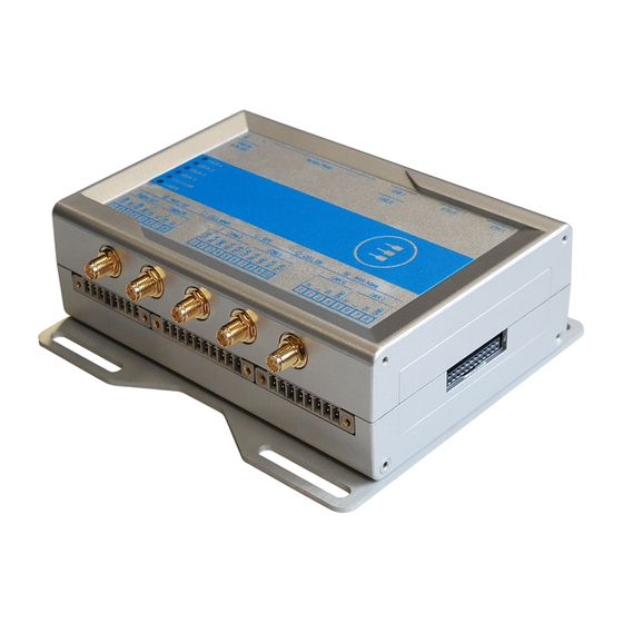
ReliaGATE 10-12 User manual Rev. 2-1 15 Mechanical specifications ECHANICAL SPECIFICATIONS 15.1 Product mechanical dimensions The product electronics are housed in an ABS enclosure having the following dimensions: 139 (L) x 115 (W) x 46 (H); mm - Antennas Connectors and Mounting Bracket included. All dimensions are in millimeters. -
Page 98: Mounting Bracket Mechanical Dimensions
15 Mechanical specifications ReliaGATE 10-12 User manual Rev. 2-1 15.2 Mounting bracket mechanical dimensions The Mounting Bracket fastened on the bottom side of the ReliaGATE 10-12 has the following dimensions. All dimensions are in millimeters. 98 / 118... -
Page 99: How To Install The Product
To simplify the installation, the ReliaGATE 10-12 is already provided with a Mounting Bracket. The Mounting Bracket is made of 2 mm aluminum alloy 6061 T6. In case of uncertainties contact the Eurotech Technical Support Team (see "How to receive technical assistance"... -
Page 100: How To Replace The Mounting Bracket With The Din Rail Mounting Clip Or Vice Versa
16 How to install the product ReliaGATE 10-12 User manual Rev. 2-1 16.2 How to replace the Mounting Bracket with the DIN Rail Mounting Clip or vice versa 16.2.1 How to replace the Mounting Bracket with the DIN Rail Mounting Clip To replace the Mounting Bracket with the DIN Rail Mounting Clip on the product, complete the following steps: 1. -
Page 101: How To Replace The Din Rail Mounting Clip With The Mounting Bracket
ReliaGATE 10-12 User manual Rev. 2-1 16 How to install the product 16.2.2 How to replace the DIN Rail Mounting Clip with the Mounting Bracket To replace the DIN Rail Mounting Clip with the Mounting Bracket on the product, complete the following steps: 1. -
Page 102: Which Screws Are Used With The Mounting Bracket Or With The Din Rail Mounting Clip
16 How to install the product ReliaGATE 10-12 User manual Rev. 2-1 16.2.3 Which screws are used with the Mounting Bracket or with the DIN Rail Mounting Clip The 3 screws that hold in place the Mounting Bracket or the DIN Rail Mounting Clip have the following features: Phillips type H cross flat countersunk head screw KA35x12 Fully threaded... -
Page 103: How To Install/ Remove The Product On/ From A Din Rail
ReliaGATE 10-12 User manual Rev. 2-1 16 How to install the product 16.3 How to install/ remove the product on/ from a DIN Rail 16.3.1 How to install the product on a DIN Rail Prerequisite: Replace the Mounting Bracket with the DIN Rail Mounting Clip To install the product on a horizontal DIN rail, complete the following steps: 1. - Page 104 (This page has been intentionally left blank)
-
Page 105: 17 Power Supply. How To Turn On/Off And Reset The Product
ReliaGATE 10-12 User manual Rev. 2-1 17 Power supply. How to turn ON/OFF and reset the product ON/OFF OWER SUPPLY OW TO TURN AND RESET THE PRODUCT This product is not provided with any ON/OFF switch. The Power IN connector is the disconnecting means from the power supply network. 17.1 Power supply specifications Power supply... -
Page 106: How To Supply Power And Turn On The Product
7. Make sure that the product maintains a proper grounding connection 8. Use a power supply that meets the product requirements and complies with the relevant standards and regulations. In case of uncertainties, contact the Eurotech Technical Support (for more information see "How to receive technical assistance"... -
Page 107: How To Turn Off The Product
ReliaGATE 10-12 User manual Rev. 2-1 17 Power supply. How to turn ON/OFF and reset the product 17.4 How to turn OFF the product To turn the ReliaGATE 10-12 OFF follow these steps: 1. Login the Administration Console 2. Enter the command poweroff. The system turns OFF 3. - Page 108 (This page has been intentionally left blank)
-
Page 109: How To Maintain The Product
ReliaGATE 10-12 User manual Rev. 2-1 18 How to maintain the product OW TO MAINTAIN THE PRODUCT Periodically inspect the product to verify its integrity and to ensure proper operation. To maintain the product, complete the following steps: 1. Carefully read and understand the instructions contained in the section "Safety instructions"... - Page 110 (This page has been intentionally left blank)
-
Page 111: Appendix 1: Advanced Boot Options
ReliaGATE 10-12 User manual Rev. 2-1 Appendix 1: Advanced boot options 1: A PPENDIX DVANCED BOOT OPTIONS Advanced boot options availability The ReliaGATE 10-12 bootloader provides a number of advanced boot options, that allow a developer to run different build artifacts. The following advanced boot options are currently available: Boot option How it works... -
Page 112: How To Change The Default Boot Option
Appendix 1: Advanced boot options ReliaGATE 10-12 User manual Rev. 2-1 1.1.3 How to change the default boot option The default boot option is fitboot which boots the production kernel fitimage. To change the default option, complete the following steps: 1. - Page 113 ReliaGATE 10-12 User manual Rev. 2-1 Appendix 1: Advanced boot options To configure the system in Linux, insert the following commands: fw_setenv fitboot ‘setenv image_path $fit_path; run imageload; bootm ${loadaddr}:kernel@1 - ${loadaddr}:fdt@reliagate-10-12-<variant>.dtb; where <variant> is either: xx, spi or gpio. To configure the system in the bootloader, insert the following commands: setenv fitboot ‘setenv image_path $fit_path;...
- Page 114 (This page has been intentionally left blank)
-
Page 115: Appendix 2: Expansion Connector Pin Map With Respect To Device Tree Pin Assignment
Appendix 2: Expansion connector pin map with respect to ReliaGATE 10-12 User manual Rev. 2-1 device tree pin assignment 2: E PPENDIX XPANSION CONNECTOR PIN MAP WITH RESPECT TO DEVICE TREE PIN ASSIGNMENT The ReliaGATE 10-12 provides an Expansion connector on the right side. For more information see: "Right Side Interface overview"... - Page 116 (This page has been intentionally left blank)
-
Page 117: Notes
ReliaGATE 10-12 User manual Rev. 2-1 Notes OTES 117 / 118... - Page 118 Via Fratelli Solari, 3/a For your Eurotech local contact refer to: eurotech.com/contacts 33020 Amaro (UD) - Italy Tel: +39 0433.485.411 For the Eurotech Global Support Centre refer to: support.eurotech.com Fax: +39 0433.485.499 Email: welcome@eurotech.com For the Eurotech Download Area refer to: eurotech.com/download...
Need help?
Do you have a question about the ReliaGATE 10-12-6 Series and is the answer not in the manual?
Questions and answers