
Subscribe to Our Youtube Channel
Related Manuals for Eurotech DynaGATE 10-06


Summary of Contents for Eurotech DynaGATE 10-06
- Page 1 User manual DynaGATE 10-06 Automotive Multi-service IoT Edge Gateway - LTE Cat 1 and IP67 Rev. 0-8 — 16 September 2020 — DYGATE-10-06_Man_ENG_0-8 — ENGLISH...
-
Page 2: Trademarks
Revision history Revision Description Date Updated FCC and IC information 16 September 2020 © 2020 Eurotech SpA - Via Fratelli Solari 3/A - 33020 AMARO (UD) - Italy... -
Page 3: Table Of Contents
DynaGATE 10-06 User manual Rev. 0-8 Contents ONTENTS Trademarks Intended audience of this document Revision history Contents 1 Safety instructions 1.1 Warning messages 1.1.1 Warning messages for harm to persons 1.1.2 Warning messages for damage to property 1.2 Warning: power supply safety 1.3 Caution: wireless safety... - Page 4 Contents DynaGATE 10-06 User manual Rev. 0-8 7.2.5 ISED Class B Digital Device Notice 7.2.6 Canadian Representative contact information 7.2.7 RF Radiation Exposure Statement 7.2.8 Labeling Information 7.3 Antennas List 7.4 REACH compliance 8 Interfaces overview 8.1 Front Side Interfaces overview 8.2 LED Indicators overview...
- Page 5 DynaGATE 10-06 User manual Rev. 0-8 Contents 12.2 How to install the product 13 How to manage the product power supply 13.1 Power supply specifications 13.2 How to supply power and turn ON the product 13.3 How to turn OFF the product 13.4 How to reduce the power consumption of the product...
- Page 6 (This page has been intentionally left blank)
-
Page 7: Safety Instructions
Failure to comply with the instructions and warnings contained in this document, violates the standards of safety, design, manufacture, and intended use of the product. Eurotech assume no liability for any damage caused by failure to observe the instructions and warnings contained in this document. -
Page 8: Warning Messages For Damage To Property
7. Make sure that the product maintains a proper grounding connection 8. Use a power supply that meets the product requirements and complies with the relevant standards and regulations. In case of uncertainties, contact the Eurotech Technical Support Team (for more information see "How to receive technical assistance"... -
Page 9: Consignes De Securite
Eurotech rejette toute responsabilité pour les dommages causés en cas de non-respect des instructions et des avertissements contenus dans ce document. En cas de doute sur la compréhension de ce document, contacter le Support Technique d’ Eurotech (pour plus d’informations voir "Comment obtenir une assistance technique"... -
Page 10: Messages D'avertissement Relatifs Aux Dommages Matériels
2 Consignes de securite DynaGATE 10-06 User manual Rev. 0-8 2.1.2 Messages d’avertissement relatifs aux dommages matériels Pour signaler les risques potentiels de détérioration du produit (ou des produits annexes), le message suivant est utilisé: AVIS Texte expliquant comment éviter d'endommager le produit (ou des produits... -
Page 11: Attention: Les Surfaces Du Produit Peuvent Devenir Chaudes
DynaGATE 10-06 User manual Rev. 0-8 2 Consignes de securite Attention: les surfaces du produit peuvent devenir chaudes Selon la température ambiante lors de l’utilisation, les surfaces du produit peuvent devenir brûlantes, engendrant un risque de brûlure. Laisser toujours les surfaces du produit refroidir avant de les toucher. - Page 12 (This page has been intentionally left blank)
-
Page 13: How To Receive Technical Assistance
3. Wait for the reply from the Support Team with the information you required How to send a product for repair Any product returned to Eurotech, that is found to be damaged due to inadequate packaging, will not be covered by the warranty. - Page 14 (This page has been intentionally left blank)
-
Page 15: Comment Obtenir Une Assistance Technique
3. Attendre la réponse de l'équipe de support avec les informations requises Comment retourner un produit en service après vente Tout produit renvoyé à Eurotech, qui se trouve endommagé en raison d'un emballage inadéquat, ne sera pas couvert par la garantie. - Page 16 (This page has been intentionally left blank)
-
Page 17: Conventions Used
DynaGATE 10-06 User manual Rev. 0-8 5 Conventions used ONVENTIONS USED Conventions for signal names Convention Description Ground Active low signal Positive signal; Positive signal in differential pair Negative signal; Negative signal in differential pair 3.3 V signal level 5 V signal level... - Page 18 (This page has been intentionally left blank)
-
Page 19: Product Overview
A rechargeable internal 2000 mA/h battery provides uninterrupted operation for up to 5 minutes in case of power failure and permits a safe shutdown. The DynaGATE 10-06 comes with a genuine Oracle Java SE Embedded 8 Virtual Machine and Everyware Software Framework (ESF), a commercial, enterprise ready edition of Eclipse Kura, the open source Java/OSGi middleware for IoT Edge Gateways. -
Page 20: Intended Use And Not Allowed Uses Of The Product
Include an external 2 A fuse on the line coming from the negative terminal of the DC power source. * For DynaGATE 10-06 versions -33 to -37: before using the DynaGATE 10-06 in automotive applications in any EU Member State, switch-off the Wi-Fi band: 5150 - 5350 MHz. -
Page 21: Technical Specifications
DynaGATE 10-06 User manual Rev. 0-8 6 Product overview Technical specifications The DynaGATE 10-06 is available in several -XY versions, for example: DynaGATE 10-06-36, where X=3 and Y=6. The following table lists the technical specifications of the DynaGATE 10-06 versions:... - Page 22 6 Product overview DynaGATE 10-06 User manual Rev. 0-8 Specifications Description according to DynaGATE 10-06-XY Version Environment Operating -40 to +85 °C Temperature Storage -40 to +85 °C Temperature Relative 5 to 95% (non condensing) at +40°C Humidity Certifications Regulatory...
-
Page 23: Product Labels
DynaGATE 10-06 User manual Rev. 0-8 6 Product overview Product labels The following labels are placed on the underside of the product: Ref # Label example Label type and content Part Number and Serial Number Label This label contains the following:... - Page 24 (This page has been intentionally left blank)
-
Page 25: Regulatory Information
DynaGATE 10-06 User manual Rev. 0-8 7 Regulatory information EGULATORY INFORMATION This section provides regulatory information for the DynaGATE 10-06 (hereafter referred to as "this "product"). Upon request, Eurotech can provide the product Declaration of Conformity. For details and more information contact the Eurotech Technical Support (see "How to receive technical... -
Page 26: Rohs 3 Compliance
"Technical specifications" on page 21. Modification statement Eurotech has not approved any changes or modifications to this product by the user. Any changes or modifications could void the user’s authority to operate this product. 7.1.6.1 EU restrictions on 5 GHz Wi-Fi usage... - Page 27 DynaGATE 10-06 User manual Rev. 0-8 7 Regulatory information 7.1.6.2 Class II product According to Commission Decision 2000/299/EC of 6 April 2000, establishing the initial classification of radio equipment and telecommunications terminal equipment and associated identifiers, the product falls within the scope of Class II.
-
Page 28: Fcc/Ised Regulatory Notices
They comply with the regulatory information reported in the following sections. Eurotech is not responsible for the use of the product together with equipment (for example: power supplies, personal computers, etc.) that are not FCC marked and not compliant with the requirements specified in this document. -
Page 29: Fcc Restrictions On 5 Ghz Wi-Fi Usage
DynaGATE 10-06 User manual Rev. 0-8 7 Regulatory information Réorienter ou déplacer l'antenne de réception Augmenter la distance entre le produit et le récepteur Brancher l'appareil sur une prise de courant différente de celle à laquelle le récepteur est raccordé... -
Page 30: Ised Class B Digital Device Notice
7 Regulatory information DynaGATE 10-06 User manual Rev. 0-8 brouillage, et (2) l’appareil doit accepter tout brouillage radioélectrique subi, même si le brouillage est susceptible d’en compromettre le fonctionnement. Le présent émetteur radio a été approuvé par Innovation, Sciences et Développement économique Canada pour fonctionner avec les types d'antenne énumérés ci dessous et ayant un gain admissible... -
Page 31: Labeling Information
FCC ID: UKMMRG1012 FCC ID: XPY1EIQ24NN IC: 21442-MRG1012 IC: 8595A-1EIQ24NN Antennas List The DynaGATE 10-06 has been certified with the following antennas: Le DynaGATE 10-06 a été certifié avec les antennes suivantes: Types Manufacturer and Model Bands Peak Gain (dBi) -
Page 32: Reach Compliance
This product has been assessed to be compliant with the regulation (EC) No. 1907/2006 (REACH) (with the exceptions allowed by the EU Technical Committee). Eurotech has set in place a monitoring process to assess compliance to REACH regulation. For details and more information contact the Eurotech Technical Support (see "How to receive technical... -
Page 33: Interfaces Overview
DynaGATE 10-06 User manual Rev. 0-8 8 Interfaces overview NTERFACES OVERVIEW Front Side Interfaces overview The Front Side Interfaces are as follows: Figure 8.1 - Front Side Interfaces layout Ref# Description LED Indicators Service Panel: includes the Service Interfaces Table 8.1 - Front Side Interfaces description... -
Page 34: Led Indicators Overview
8 Interfaces overview DynaGATE 10-06 User manual Rev. 0-8 LED Indicators overview The LED Indicators are as follows: Figure 8.2 - LED Indicators layout Ref# Label Color General purpose. Controllable by user software Bi-color Green/Amber General purpose. Controllable by user software... -
Page 35: Service Panel And Service Interfaces
DynaGATE 10-06 User manual Rev. 0-8 8 Interfaces overview Service Panel and Service Interfaces 8.3.1 Service Panel Overview Ref# Description Service Panel: includes the Service Interfaces 8.3.1.1 How to Remove the Service Panel Cover NOTICE The IP grade is not maintained when the Service Panel cover is removed. -
Page 36: Service Interfaces Overview
8 Interfaces overview DynaGATE 10-06 User manual Rev. 0-8 8.3.2 Service Interfaces Overview The DynaGATE 10-06 has the following Service Interfaces: Figure 8.3 - Service Interfaces layout Ref# Description 3.3 V TTL Serial Console Logic 1 (Hi): 2.0 to 3.3 V Logic 0 (Low): 0 to 0.8 V... - Page 37 DynaGATE 10-06 User manual Rev. 0-8 8 Interfaces overview 8.3.2.1 TTL Serial console connector specifications Connector Layout: Connector Pinout: Pin # Signal Type Description Ground Transmit Data Connector Specifications: Receive Data Shrouded header Gender: Male Type: Pitch 1.25 mm; 3-pin...
- Page 38 8 Interfaces overview DynaGATE 10-06 User manual Rev. 0-8 8.3.2.4 Boot Modes Selection DIP-switch The DynaGATE 10-06 has the following Boot Modes: Main Programmed To select the Boot Modes, set up the Boot Modes Selection DIP-switch according to the following table:...
-
Page 39: Rear Side Overview
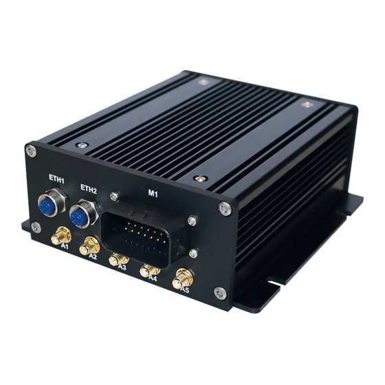
DynaGATE 10-06 User manual Rev. 0-8 8 Rear Side Overview VERVIEW The Rear Side is as follows: Figure 8.4 - Rear Side layout Ref# Label Connector for ETH1 1x Fast Ethernet ETH2 1x Fast Ethernet 2x CAN bus, Not-Isolated 1 x RS-485, Not Isolated, Surge Protected... -
Page 40: Connectors Eth1 And Eth2
8 Rear Side Overview DynaGATE 10-06 User manual Rev. 0-8 8.3.1 Connectors ETH1 and ETH2 Connector Layout: Connector Pinout: Pin # Signal Type Description Male RJ45 Pin # TX+_D1 Transmit Data + RX+_D2 Receive Data + TX-_D1 Transmit Data -... -
Page 41: Connector M1
DynaGATE 10-06 User manual Rev. 0-8 8 Rear Side Overview 8.3.2 Connector M1 Connector Layout: Connector Pinout: Pin # Signal Type Description CAN0 H CAN port 0 Positive Data CAN0 L CAN port 0 Negative Data Ground CAN1 H CAN port 1 Positive Data... -
Page 42: Connectors A1, A4, A5
8 Rear Side Overview DynaGATE 10-06 User manual Rev. 0-8 8.3.3 Connectors A1, A4, A5 Connector Layout: Connector Pinout: Pin # Description Female inner pin contact Female connector body (outer thread) Connector Specifications: SMA connector Gender: Female Mating Connector Specifications: SMA connector Gender: Male 8.3.4... -
Page 43: Features In Detail
9 Features in detail EATURES IN DETAIL Wi-Fi and Bluetooth (only for versions: -33 to -37) The DynaGATE 10-06 provides the following Wi-Fi / Bluetooth functionality: 2.5 GHz Wi-Fi 802.11a,b,g,n / BLE 4.2 BLE Bluetooth 5 GHz Wi-Fi 802.11a,b,g,n The internal circuitry allows for 2.5 GHz Wi-Fi and Bluetooth coexistence. -
Page 44: Bluetooth Specifications
9 Features in detail DynaGATE 10-06 User manual Rev. 0-8 9.1.2 Bluetooth specifications Supports Bluetooth 4.2 as well as CSA2 Includes concurrent operation and built -in coexisting and prioritization handling of Bluetooth, BLE, audio processing and WLAN Dedicated Audio processor supporting on chip SBC encoding + A2DP:... -
Page 45: Internal Mobile Connectivity (Only For Versions: -34 To -37)
DynaGATE 10-06 User manual Rev. 0-8 9 Features in detail Internal mobile connectivity (only for versions: -34 to -37) The DynaGATE 10-06 supports the following u-blox LARA-R2 modem variants, according to product versions based on the geographic area of usage: DynaGATE 10-06-XY Version... - Page 46 9.2.1.5 LTE - Single Antenna Operation For optimum performance of the cellular interface Eurotech recommends the use of both Main and Diversity antenna connectors. Single antenna operation can be supported, however typically cellular carriers impose restrictions on single antenna operation.
- Page 47 DynaGATE 10-06 User manual Rev. 0-8 9 Features in detail 9.2.1.7 Second antenna requirements (for antenna diversity) Feature Description Impedance 50 Ohm Frequency range The required frequency range of the antenna connected depends on the operating bands of the used cellular module and the used mobile network.
-
Page 48: 1St And 2Nd Microsim Card Holders
9.2.2 1st and 2nd MicroSIM Card holders The DynaGATE 10-06 has two push-push MicroSIM card holders in the Service Panel, placed on the bottom side of the circuit board. If you use only one MicroSIM card: insert it in the 1st holder. -
Page 49: Internal Gnss (Only For Versions: -32 To -37)
DynaGATE 10-06 User manual Rev. 0-8 9 Features in detail Internal GNSS (only for versions: -32 to -37) The DynaGATE 10-06 provides the following GNSS functionality: Dead Reckoning; 72 channels GPS/QZSS, GLONASS, BeiDou, Galileo. The antenna connector is A1 (see also "Connectors A1, A4, A5"... -
Page 50: Digital I/Os
9 Features in detail DynaGATE 10-06 User manual Rev. 0-8 Digital I/Os The DynaGATE 10-06 has the following Digital I/Os: 1x Insulated Digital Input 1x Insulated Digital Output The Digital I/Os are available on the connector M1 (see also "Connector M1" on page 41). -
Page 51: Insulated Digital Outputs
DynaGATE 10-06 User manual Rev. 0-8 9 Features in detail 9.4.2 Insulated Digital Outputs 9.4.2.1 Electrical specifications The table below shows the electrical specifications of the digital outputs: Characteristic Value Maximum Voltage 60 V Maximum Current 500 mA Output ON Resistance Typical: 0.85 Ohm... -
Page 52: Com Ports
9 Features in detail DynaGATE 10-06 User manual Rev. 0-8 COM ports The DynaGATE 10-06 has two COM ports: 1 x RS-485 1 x RS-232 The COM ports are available on the connector M1 (see also "Connector M1" on page 41). -
Page 53: Can Ports
DynaGATE 10-06 User manual Rev. 0-8 9 Features in detail CAN ports The DynaGATE 10-06 has two CAN ports: CAN0 CAN1 The CAN ports are available on the connector M1 (see also "Connector M1" on page 41). 9.6.1 CAN specifications Feature... -
Page 54: Ethernet Ports
9 Features in detail DynaGATE 10-06 User manual Rev. 0-8 Ethernet ports The DynaGATE 10-06 provides two 10/100 Mbps Ethernet ports: ETH1 ETH2. The Ethernet connectors are ETH1 and ETH2 (see also "Connectors ETH1 and ETH2" on page 40). 9.7.1 Ethernet specifications... -
Page 55: Microsd Card Holder
9 Features in detail MicroSD card holder The DynaGATE 10-06 has one push-push MicroSD card holder in the Service Panel, placed on the top side of the circuit board. The MicroSD card holder allows you to insert a MicroSD card for additional data storage (up to 32 GB) 9.8.0.1... - Page 56 (This page has been intentionally left blank)
-
Page 57: Eurotech Everyware Iot
ESF allows the connection and communication with field devices (close to data sources), thanks to already tested libraries for field protocol communication, the visual IoT Edge Computing applications development and the connection with leading IoT Cloud Services such as Everyware Cloud (Eurotech IoT Integration Platform) , Eclipse Kapua, AWS IoT and Microsoft Azure IoT. -
Page 58: The Esf Web Ui
10 Eurotech Everyware IoT DynaGATE 10-06 User manual Rev. 0-8 10.2 The ESF Web UI ESF provides a web-based user interface: ESF Web UI. The ESF Web UI provides several functions such as: Monitor the gateway status Manage the network configuration Oversee the installed application(s) and services. -
Page 59: The Esf Wires Application
DynaGATE 10-06 User manual Rev. 0-8 10 Eurotech Everyware IoT 10.3 The ESF Wires application ESF provides also a dataflow programming model: Wires. Wires simplifies the development of Edge Computing Applications leveraging reusable configurable components. In the dataflow programming model, the application logic is expressed as a directed graph (flow) where each node can have inputs, outputs and independent processing units. -
Page 60: Everyware Cloud (Ec)
10.4 Everyware Cloud (EC) Eurotech’s Everyware™ Cloud (EC) is an IoT Integration Platform that simplifies system and data management by connecting distributed devices over secure and reliable cloud services. Everyware Cloud allows you to connect, configure and manage devices through all the lifecycle, from deployment through maintenance to retirement. -
Page 61: Mechanical Specifications
DynaGATE 10-06 User manual Rev. 0-8 11 Mechanical specifications ECHANICAL SPECIFICATIONS 11.1 Product mechanical dimensions The product electronics are housed in an aluminium alloy enclosure having the following dimensions: 165 (L) x 160 (W) x 62 (H); mm - Mounting Brackets included, Connectors not included. - Page 62 (This page has been intentionally left blank)
-
Page 63: How To Install The Product
(for example use 4x M6 screws, with a minimum length of 15 mm). Material and length of the screws, and the maximum torque applicable, depend on your installation requirements. In case of uncertainties contact the Eurotech Technical Support Team. For more information see "How to receive technical assistance" on page 13. - Page 64 (This page has been intentionally left blank)
-
Page 65: How To Manage The Product Power Supply
13.1 Power supply specifications The DynaGATE 10-06 provides the Power IN interface within the M1 connector: Pin 21 is the Ignition Key Input (KEY IN), a digital input that can be used to turn ON/OFF the DynaGATE 10-06. For more information see: Insert Link... -
Page 66: How To Supply Power And Turn On The Product
DynaGATE 10-06 4. Connect the DC power source terminals ("Power IN +" and "Power IN -") to Pins 22 and 23 of the M1 connector: 5. Turn ON the DC power source. The DynaGATE 10-06 remains OFF 66 / 72... -
Page 67: How To Turn Off The Product
How to turn OFF the product To turn OFF the DynaGATE 10-06, follow these steps: 1. Disconnect the KEY IN from Power IN +. The DynaGATE 10-06 performs a safe shut down 2. Disconnect the DC power source terminals from the Power IN interface. - Page 68 (This page has been intentionally left blank)
-
Page 69: How To Maintain The Product
DynaGATE 10-06 User manual Rev. 0-8 14 How to maintain the product OW TO MAINTAIN THE PRODUCT Periodically inspect the product to verify its integrity and to ensure proper operation. To maintain the product, complete the following steps: 1. Carefully read and understand the instructions contained in the section "Safety instructions"... - Page 70 (This page has been intentionally left blank)
-
Page 71: Notes
DynaGATE 10-06 User manual Rev. 0-8 Notes OTES 71 / 72... - Page 72 Via Fratelli Solari, 3/a For your Eurotech local contact refer to: eurotech.com/contacts 33020 Amaro (UD) - Italy Tel: +39 0433.485.411 For the Eurotech Global Support Centre refer to: support.eurotech.com Fax: +39 0433.485.499 Email: welcome@eurotech.com For the Eurotech Download Area refer to: eurotech.com/download...
Need help?
Do you have a question about the DynaGATE 10-06 and is the answer not in the manual?
Questions and answers