
Related Manuals for Eurotech DynaGATE 20-30 Series


Summary of Contents for Eurotech DynaGATE 20-30 Series
- Page 1 User manual DynaGATE 20-30-xx Automotive Multi-service IoT Edge Gateway Intel Atom, LTE Cat 4/6 Rev. 0-7 — 29 March 2021 — DYGATE-20-30_Man_ENG_0-7 — ENGLISH...
-
Page 2: Trademarks
Preliminary release. 12 March 2021 Updated sections: 6.4 "Technical specifications" 9.9 "Earth connection terminal" Preliminary release. 29 March 2021 Updated section: 7.2.7 "RF Radiation Exposure Statement" © 2021 Eurotech SpA - Via Fratelli Solari 3/A - 33020 AMARO (UD) - Italy... -
Page 3: How To Get Started
For more information see: "Safety instructions" on page 9. Whenever in doubt regarding the correct understanding of this document, contact the Eurotech Technical Support. For more information see: "How to receive technical assistance" on page 17 2. - Page 4 (This page has been intentionally left blank)
-
Page 5: Table Of Contents
DynaGATE 20-30 User manual Rev. 0-7 Contents ONTENTS Trademarks Intended audience of this document Revision history How to get started Contents 1 Safety instructions 1.1 Warning messages 1.1.1 Warning messages for harm to persons 1.1.2 Warning messages for damage to property 1.2 Warning: power supply safety 1.3 Caution: product's surfaces may become hot 1.4 Caution: wireless safety... - Page 6 Contents DynaGATE 20-30 User manual Rev. 0-7 7.2.3 FCC restrictions on 5 GHz Wi-Fi usage 7.2.4 ISED Canada compliance 7.2.5 ISED Class B Digital Device Notice 7.2.6 Responsible parties: Canadian Representative contact information 7.2.7 RF Radiation Exposure Statement 7.2.8 Labeling information 7.3 Antennas List 7.4 RoHS 3 compliance 7.5 REACH compliance...
- Page 7 9.15 RTC (Real Time Clock) 9.16 TPM 9.17 Watchdog 9.18 Accelerometer and Gyroscope 9.19 Programmable pushbutton 10 Eurotech Everyware IoT 10.1 Everyware Software Framework (ESF) 10.2 The ESF Web UI 10.3 The ESF Wires application 10.4 Everyware Cloud (EC) 10.5 For more information 11 Mechanical specifications and dimensions 11.1 Product mechanical specifications...
- Page 8 (This page has been intentionally left blank)
-
Page 9: Safety Instructions
Failure to comply with the instructions and warnings contained in this document, violates the standards of safety, design, manufacture, and intended use of the product. Eurotech assume no liability for any damage caused by failure to observe the instructions and warnings contained in this document. -
Page 10: Warning Messages For Damage To Property
8. Make sure that the product maintains a proper grounding connection 9. Use a power supply that meets the product requirements and complies with the relevant standards and regulations. In case of uncertainties, contact the Eurotech Technical Support Team (for more information see "How to receive technical assistance"... -
Page 11: Caution: Wireless Safety
DynaGATE 20-30 User manual Rev. 0-7 1 Safety instructions Caution: wireless safety CAUTION The antennas used with the product must be installed with care, avoiding any interference with other electronic devices and keeping a distance from persons greater than 20 cm. If these requirements cannot be satisfied, the system integrator has to assess the final product with respect to SAR regulations. - Page 12 (This page has been intentionally left blank)
-
Page 13: Consignes De Securite
Eurotech rejette toute responsabilité pour les dommages causés en cas de non-respect des instructions et des avertissements contenus dans ce document. En cas de doute sur la compréhension de ce document, contacter le Support Technique d’ Eurotech (pour plus d’informations voir "Comment obtenir une assistance technique"... -
Page 14: Messages D'avertissement Relatifs Aux Dommages Matériels
"Earth connection terminal" page 52 8. Utiliser une alimentation électrique conforme aux exigences du produit et conforme aux normes et réglementations en vigueur. En cas d'incertitude, contacter l'équipe d'assistance technique d'Eurotech (pour plus d'informations, voir "Comment obtenir une assistance technique" page 9. -
Page 15: Attention: Sécurité Sur La Connectivité Sans Fil
DynaGATE 20-30 User manual Rev. 0-7 2 Consignes de securite Attention: sécurité sur la connectivité sans fil ATTENTION Les antennes utilisées avec le produit doivent être installées avec soin, en évitant toute interférence avec d'autres appareils électroniques et à au moins 20 cm des personnes. Si ces exigences ne peuvent être satisfaites, l'intégrateur du système doit évaluer le produit final par rapport à... - Page 16 (This page has been intentionally left blank)
-
Page 17: How To Receive Technical Assistance
3. Wait for the reply from the Eurotech Technical Support with the information you required How to send a product for repair Any product returned to Eurotech, that is found to be damaged due to inadequate packaging, will not be covered by the warranty. - Page 18 (This page has been intentionally left blank)
-
Page 19: Comment Obtenir Une Assistance Technique
3. Attendre la réponse de l'équipe de support avec les informations requises Comment retourner un produit en service après vente Tout produit renvoyé à Eurotech, qui se trouve endommagé en raison d'un emballage inadéquat, ne sera pas couvert par la garantie. - Page 20 (This page has been intentionally left blank)
-
Page 21: Conventions Used
Negative signal; Negative signal in differential pair 3.3 V signal level 5 V signal level No Connection Reserved Use is reserved to Eurotech Conventions for signal types Convention Description Signal is an input to the system Signal is an output from the system... - Page 22 (This page has been intentionally left blank)
-
Page 23: Product Overview
J1939 and J1708 standards. Vehicle data can then be analyzed on the Edge and published to the Cloud though the popular MQTT protocol. Everyware Cloud, Eurotech IoT Integration Platform, completes this solution by providing data integration to the applications and by offering complete management of the devices deployed on the field. -
Page 24: Product Label
The product label is placed on the bottom side of the product: Ref# Label example Label content Product Number Model Number Serial Number MAC ID Number Eurotech logo Manufacturer address FCC ID and IC codes Power supply requirements(*) IP Code CE Mark, FCC Mark, E-Mark WEEE symbol (*) The symbol... -
Page 25: Intended Use And Not Allowed Uses Of The Product
DynaGATE 20-30 User manual Rev. 0-7 6 Product overview Intended use and not allowed uses of the product The product is intended for professional use and must be installed by qualified personnel only. The product must be installed in a secured location, accessible to authorized personnel only (for example in a cabinet / technical compartment). -
Page 26: Technical Specifications
6 Product overview DynaGATE 20-30 User manual Rev. 0-7 Technical specifications According to the respective product versions, the specifications are as follows: Specifications Description according to product versions -10/-30(*) -11/-31(*) -20/-40(*) -21/-41(*) -22/-42(*) PROCESSOR Intel Atom x5- Intel Atom x5 - E3940, Intel Atom x7 - E3950, 1.60GHz (1.80GHz), 1.60GHz (2.00GHz),... - Page 27 DynaGATE 20-30 User manual Rev. 0-7 6 Product overview Specifications Description according to product versions -10/-30(*) -11/-31(*) -20/-40(*) -21/-41(*) -22/-42(*) ANTENNA CONNECTORS 2x SMA (Cellular with Antenna Diversity); Vers: -10, -20, -22 2x RP-SMA (Wi-Fi/BT) 1x SMA (GNSS) SPECIAL Ultra-low Wake-On-Ring/SMS Wake-On-RTC Alarm FEATURES...
- Page 28 Everyware Software Framework (ESF)(*) Framework (*) Product versions: -00, -10, -11, -20, -21, -22 include Eurotech Everyware Linux Product versions: -30, -31, -40, -41, -42 include Everyware Software Framework (**) Cellular modem is certified in several countries, DYGATE-20-30 country specific certification upon request (§) UL, NRTL listing Factory Option...
-
Page 29: Regulatory Information
This product is CE marked and complies with the regulatory information reported in the following sections. Eurotech is not responsible for the use of this product together with equipment (for example: power supplies, personal computers, etc.) that are not CE marked and not compliant with the requirements specified in this document. -
Page 30: Red 2014/53/Eu Compliance
For more information see "Technical specifications" on page 26. Modification statement Eurotech does not approve any changes or modifications to this product by the user. Any changes or modifications could void the user’s authority to operate this product. 7.1.6.1 Class II product... - Page 31 DynaGATE 20-30 User manual Rev. 0-7 7 Regulatory information 7.1.6.2 EU restrictions on 5 GHz Wi-Fi usage Channel Number Frequency (MHz) Europe (ETSI) 5180 Indoor Usage Only 5200 Indoor Usage Only 5220 Indoor Usage Only 5240 Indoor Usage Only 5260 Not Supported 5280 Not Supported...
-
Page 32: Fcc/Ised Compliance
They comply with the regulatory information reported in the following sections. Eurotech is not responsible for the use of the product together with equipment (for example: power supplies, personal computers, etc.) that are not FCC marked and not compliant with the requirements specified in this document. -
Page 33: Fcc Restrictions On 5 Ghz Wi-Fi Usage
DynaGATE 20-30 User manual Rev. 0-7 7 Regulatory information Réorienter ou déplacer l'antenne de réception Augmenter la distance entre le produit et le récepteur Brancher l'appareil sur une prise de courant différente de celle à laquelle le récepteur est raccordé Consulter le revendeur ou un technicien radio/TV expérimenté... -
Page 34: Ised Canada Compliance
7 Regulatory information DynaGATE 20-30 User manual Rev. 0-7 7.2.4 ISED Canada compliance This device contains licence-exempt transmitter(s)/receiver(s) that comply with Innovation, Science and Economic Development Canada’s licence-exempt RSS(s). Operation is subject to the following two conditions: (1) this device may not cause harmful interference, and (2) this device must accept any interference received, including interference that may cause undesired operation. -
Page 35: Rf Radiation Exposure Statement
DynaGATE 20-30 User manual Rev. 0-7 7 Regulatory information 7.2.7 RF Radiation Exposure Statement This product complies with FCC and ISED radiation exposure limits set forth for an uncontrolled environment. The antenna should be installed and operated with minimum distance of 20 cm between the radiator and your body. -
Page 36: Rohs 3 Compliance
Parliament and of the Council of 18 December 2006 concerning the Registration, Evaluation, Authorisation and Restriction of Chemicals (REACH), with the exceptions allowed by the EU Technical Committee. Eurotech has set in place a monitoring process to assess compliance to REACH regulation. For details and more information contact the Eurotech Technical Support (see "How to receive technical... -
Page 37: Interfaces Overview
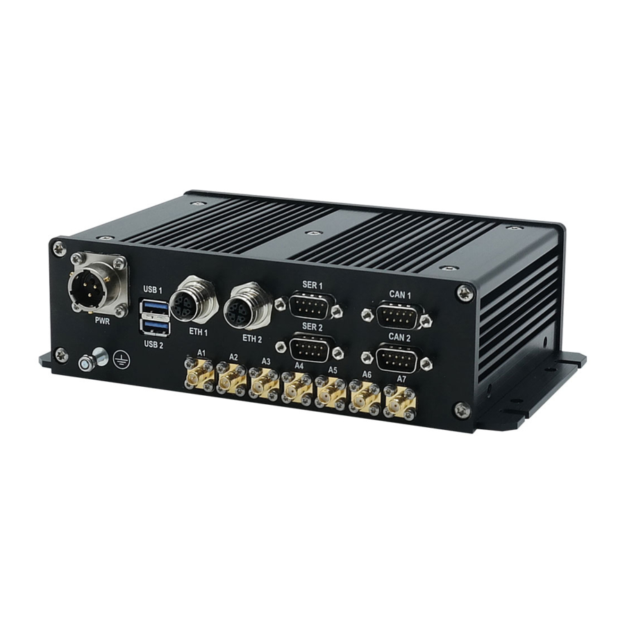
DynaGATE 20-30 User manual Rev. 0-7 8 Interfaces overview NTERFACES OVERVIEW Rear Side Interfaces overview The Rear Side Interfaces are as follows: Figure 8.1 - Rear Side Interfaces layout Ref# Label Description Power IN Connector (Size 12, 3-pin MIL-26482 Male) USB 0 1x USB 3.0 port Noise and Surge Protected USB 1... -
Page 38: Front Side Interfaces Overview
8 Interfaces overview DynaGATE 20-30 User manual Rev. 0-7 Front Side Interfaces overview The Front Side Interfaces are as follows: Figure 8.2 - Front Side Interfaces layout Ref# Description LED indicators Service Panel Display Port 3x Isolated Digital Inputs 3x Isolated Digital Outputs 2x Not Isolated Analog Inputs Table 8.2 - Front Side Interfaces description 38 / 76... -
Page 39: Service Panel Interfaces
DynaGATE 20-30 User manual Rev. 0-7 8 Interfaces overview 8.2.1 Service Panel Interfaces The Interfaces available in the Service Panel are as follows: Figure 8.3 - Service Interfaces layout Ref# Description Audio Connector MicroSD card receptacle (push-push) (up to 32 GB MicroSD cards) MicroSIM care receptacle (push-push) USB 2.0 port (USB2) Reserved... -
Page 40: Led Indicators Overview
8 Interfaces overview DynaGATE 20-30 User manual Rev. 0-7 LED Indicators overview The LED Indicators are as follows: Figure 8.4 - LED Indicators layout Ref# Description Color User 1 Dual Color (Green / Amber) MiniPCIe Slot #3 Green User 2 Dual Color (Green / Amber) MiniPCIe Slot #2 Green... -
Page 41: Interfaces In Detail
DynaGATE 20-30 User manual Rev. 0-7 9 Interfaces in detail NTERFACES IN DETAIL Wi-Fi and Bluetooth The DynaGATE 20-30 provides wireless local area network (WLAN) connectivity, in conformity with the IEEE 802.11ac/abgn Wi-Fi standard and in coexistence with BT 5.0. The antennas connectors are placed on the rear side. -
Page 42: Antennas Connectors Specifications
9 Interfaces in detail DynaGATE 20-30 User manual Rev. 0-7 Feature Description RF Output Power 802.11a: 15.5 dBm at 54M ±2 dBm (Typical - Conductive) 802.11b: 18 dBm at 11M ±2 dBm 802.11g: 15.5 dBm at 54M ±2 dBm 802.11n 5G HT20: 17 dBm at MCS0 15 dBm at MCS7 ±2 dBm... -
Page 43: Internal Cellular Modem
DynaGATE 20-30 User manual Rev. 0-7 9 Interfaces in detail Internal Cellular Modem Versions -10, -20, -22 of the DynaGATE 20-30 supports a Global LTE Cat 4 Cellular Modem. The antennas connectors are placed on the rear side. 9.2.1 Internal Cellular Modem specifications Feature Description Key Features... -
Page 44: Lte - Single Antenna Operation Notes
Operators) impose restrictions. Please consult with your carrier before considering single LTE antenna usage. For optimum performance of the cellular interface, Eurotech recommends the use of both CELL MAIN and CELL DIV antenna connectors. If CELL DIV antenna is not used/connected, Eurotech recommends to disable the diversity function: see... -
Page 45: Microsim Card Receptacles
DynaGATE 20-30 User manual Rev. 0-7 9 Interfaces in detail MicroSIM card receptacles The DynaGATE 20-30 includes the following push-push MicroSIM card receptacles in the Service Panel: 1st MicroSIM card receptacle, placed on the top side of the circuit board 2nd MicroSIM card receptacle, placed on the bottom side of the circuit board If you have only one SIM card, use the 1st MicroSIM card receptacle. -
Page 46: Gnss
9 Interfaces in detail DynaGATE 20-30 User manual Rev. 0-7 GNSS The DynaGATE 20-30 provides the following GNSS features according to the product version. Active or passive antenna supported. The antenna connector is placed on the rear side. 9.4.1 GNSS features for versions -10, -11, -20, -21 Feature Description Receiver type... -
Page 47: Antenna Connector Specifications
DynaGATE 20-30 User manual Rev. 0-7 9 Interfaces in detail 9.4.3 Antenna connector specifications Connector Layout: Connector Pinout: Pin # Description Female inner pin contact Female connector body (outer thread) Connector Specifications: SMA connector Gender: Female Mating Connector Specifications: SMA connector Gender: Male 47 / 76... -
Page 48: Usb 0, Usb 1, Usb 2
9 Interfaces in detail DynaGATE 20-30 User manual Rev. 0-7 USB 0, USB 1, USB 2 The DynaGATE 20-30 provides the following Host USB ports: USB 0: USB 3.0, on the Rear Side, top port(Noise and Surge Protected USB 1: USB 2.0, on the Rear Side, bottom port (Noise and Surge Protected) USB 2: USB 2.0, in the Service Panel (ready for optional accessories, e.g.: ReliaCELL 10-20) 9.5.1 USB 0 connector specifications... -
Page 49: Usb 2 Connector Specifications
DynaGATE 20-30 User manual Rev. 0-7 9 Interfaces in detail 9.5.3 USB 2 connector specifications Connector Layout: Connector Pinout: Pin # Signal Type Description Data- Data+ Ground Connector Specifications: USB Type-A socket Gender: Female Mating Connector Specifications: USB Type-A plug Gender: Male 49 / 76... -
Page 50: Eth 0, Eth
9 Interfaces in detail DynaGATE 20-30 User manual Rev. 0-7 ETH 0, ETH 1 The DynaGATE 20-30 provides 2x 10/100/1000 Mbps Ethernet ports: ETH 0 ETH 1 The Ethernet connectors are available on the Rear Side. 9.6.1 Ethernet specifications Feature Description Network Standard 10BASE-Te/100BASE-Tx/1000 BASE-T IEEE 802.3 compliant... -
Page 51: Com 0, Com 1
DynaGATE 20-30 User manual Rev. 0-7 9 Interfaces in detail COM 0, COM 1 The DynaGATE 20-30 provides the following COM ports: COM 0: RS-485/RS-422 Isolated on the Rear Side (Default: RS-485 Full Duplex) COM 1: 1x RS-232/RS-485/RS-422 Isolated on the Rear Side(Default: RS-232) The COM connectors are available on the Rear Side. -
Page 52: Can 0, Can 1
9 Interfaces in detail DynaGATE 20-30 User manual Rev. 0-7 CAN 0, CAN 1 The DynaGATE 20-30 provides 2x CAN (Controller Area Network) ports compliant with the CAN Specification 2.0, Parts A and B: CAN 0 CAN 1 The CAN connectors are available on the rear side. Notes about CAN power supply: The DynaGATE 20-30 can supply power to the 2 CAN ports: 100mA @ 5V (each port) CAN power can be enabled / disabled by software... -
Page 53: Display Port
DynaGATE 20-30 User manual Rev. 0-7 9 Interfaces in detail 9.10 Display Port The DynaGATE 20-30 provides a mini DisplayPort connector on the Front Side. 9.10.1 Display Port connector specifications Connector Layout: Connector Pinout: Pin # Signal Type Description GND1 Ground Hot Plug Detect Lane 0 (positive) -
Page 54: Digital I/O And Analog In
9 Interfaces in detail DynaGATE 20-30 User manual Rev. 0-7 9.11 Digital I/O and Analog IN The DynaGATE 20-30 provides the following I/Os: 3x Isolated Digital Inputs 3x Isolated Digital Outputs 2x Not Isolated Analog Inputs (Factory Option: Odometer input) The I/O connector is available on the Front Side. -
Page 55: Insulated Digital Inputs
DynaGATE 20-30 User manual Rev. 0-7 9 Interfaces in detail 9.11.2 Insulated Digital Inputs 9.11.2.1 Electrical specifications The table below shows the electrical specifications of the digital inputs at 24VDC of nominal supply voltage: Characteristic Value @ 24 VDC Logic Zero 0 V ≤... -
Page 56: Insulated Digital Outputs
9 Interfaces in detail DynaGATE 20-30 User manual Rev. 0-7 9.11.3 Insulated Digital Outputs 9.11.3.1 Electrical specifications The table below shows the electrical specifications of the digital outputs at 24VDC of nominal supply voltage: Characteristic Value @ 24 VDC Maximum Current 250 mA Output ON Resistance Typical: 0.85 Ohm... -
Page 57: Audio Connector
DynaGATE 20-30 User manual Rev. 0-7 9 Interfaces in detail 9.12 Audio connector The DynaGATE 20-30 provides an audio connector in the Service Panel. 9.12.1 Audio connector specifications Connector Layout: Connector Pinout: Pin # Signal Type Description OUT_L+ Left Line PositiveOut OUT_L- Left Line Negative Out Connector Specifications:... -
Page 58: Ttl Serial Console
9 Interfaces in detail DynaGATE 20-30 User manual Rev. 0-7 9.13 TTL Serial Console The DynaGATE 20-30 provides a 3.3 V TTL compatible Serial Console in the Service Panel. The voltage levels are as follows: Log 1 (Hi): 2.0 to 3.3 V Log 0 (Low): 0 to 0.8 V 9.13.1 TTL Serial Console connector specifications... -
Page 59: Microsd Card Receptacle
DynaGATE 20-30 User manual Rev. 0-7 9 Interfaces in detail 9.14 MicroSD card receptacle The MicroSD card receptacle is placed on the top side of the circuit board in the Service Panel. The receptacle allows you to insert a MicroSD card (up to 32 GB) for additional data storage. 9.14.1 How to insert / remove the MicroSD card in the receptacle To insert the MicroSD card, complete the following steps:... -
Page 60: Rtc (Real Time Clock)
9 Interfaces in detail DynaGATE 20-30 User manual Rev. 0-7 9.15 RTC (Real Time Clock) The DynaGATE 20-30 includes an RTC (Real Time Clocks) device with Fast Reboot Support. A SuperCAP allows for up to 2 Months Retain. 9.16 The DynaGATE 20-30 includes a TPM 2.0 hardware module: Infineon SLB9670. This is connected to the CPU via an SPI interface. -
Page 61: Eurotech Everyware Iot
DynaGATE 20-30 User manual Rev. 0-7 10 Eurotech Everyware IoT UROTECH VERYWARE Everyware IoT is an IoT platform providing hardware and software building blocks with an open, integrated and managed core to allow flexibility and interoperability across different vendors, to reduce time to market and for seamless integration between OT (operational technology) domain and IT (information technology) domain. -
Page 62: The Esf Wires Application
10 Eurotech Everyware IoT DynaGATE 20-30 User manual Rev. 0-7 10.3 The ESF Wires application ESF provides also a dataflow programming model: Wires. Wires simplifies the development of Edge Computing Applications leveraging reusable configurable components. In the dataflow programming model, the application logic is expressed as a directed graph (flow) where each node can have inputs, outputs and independent processing units. -
Page 63: Everyware Cloud (Ec)
10.4 Everyware Cloud (EC) Everyware Cloud (EC) is the IoT Integration Platform distributed and supported by Eurotech. It provides all the services required for the management of IoT gateways and devices in the field, including configuration management, application life-cycle management and remote access. - Page 64 (This page has been intentionally left blank)
-
Page 65: Mechanical Specifications And Dimensions
DynaGATE 20-30 User manual Rev. 0-7 11 Mechanical specifications and dimensions ECHANICAL SPECIFICATIONS AND DIMENSIONS 11.1 Product mechanical specifications The product enclosure has the following specifications: Material: Aluminium Color: Black Anodized 11.2 Product mechanical dimensions The product enclosure has the following dimensions: 224 (W) x 128 (D) x 62 (H), mm (connectors excluded). - Page 66 (This page has been intentionally left blank)
-
Page 67: How To Install The Product
(for example use 4x M5 screws, with a minimum length of 15 mm). Material, type, and length of the screws, and the maximum torque applicable, depend on your installation requirements. In case of uncertainties contact the Eurotech Technical Support Team (see "How to receive technical assistance" on page 17). -
Page 68: Respect The Clearance Space
12 How to install the product DynaGATE 20-30 User manual Rev. 0-7 12.1 Respect the clearance space To ensure: proper air circulation around the product, and adequate space to install the product, respect the clearance space indicated in orange in the following figure (dimensions are in mm): Figure 12.1 - Clearance space 68 / 76... -
Page 69: 13 Power Supply. How To Turn On/Off And Reset The Product
DynaGATE 20-30 User manual Rev. 0-7 13 Power supply. How to turn ON/OFF and reset the product ON/OFF OWER SUPPLY OW TO TURN AND RESET THE PRODUCT This product is not provided with any ON/OFF switch. The Power IN connector is the disconnecting means from the power supply network. 13.1 Power supply specifications Power supply... -
Page 70: How To Supply Power To The Product And Turn It On
8. Make sure that the product maintains a proper grounding connection 9. Use a power supply that meets the product requirements and complies with the relevant standards and regulations. In case of uncertainties, contact the Eurotech Technical Support Team (for more information see "How to receive technical assistance"... - Page 71 DynaGATE 20-30 User manual Rev. 0-7 13 Power supply. How to turn ON/OFF and reset the product 5. Connect the Earth connection terminal (Ref# E below) to an earth point in the installation 6. Connect the Power IN connector (Ref# A and C below) to the DC power source terminals (DC IN+ and DC IN-) Ref# Description...
-
Page 72: Note About The Vehicle Ignition Sense
13 Power supply. How to turn ON/OFF and reset the product DynaGATE 20-30 User manual Rev. 0-7 13.3.1 Note about the Vehicle Ignition Sense The Vehicle Ignition Sense is a digital input that can be used to read the status of the KEY Pin. 13.4 How to turn OFF the product There are two ways to turn OFF the DynaGATE 20-30:... -
Page 73: How To Maintain The Product
DynaGATE 20-30 User manual Rev. 0-7 14 How to maintain the product OW TO MAINTAIN THE PRODUCT Periodically inspect the product to verify its integrity and to ensure proper operation. To maintain the product, complete the following steps: 1. Carefully read and understand the instructions contained in the section "Safety instructions"... - Page 74 (This page has been intentionally left blank)
-
Page 75: Notes
DynaGATE 20-30 User manual Rev. 0-7 Notes OTES 75 / 76... - Page 76 Via Fratelli Solari, 3/a For your Eurotech local contact refer to: eurotech.com/contacts 33020 Amaro (UD) - Italy Tel: +39 0433.485.411 For the Eurotech Global Support Centre refer to: support.eurotech.com Fax: +39 0433.485.499 Email: welcome@eurotech.com For the Eurotech Download Area refer to: eurotech.com/download...
Need help?
Do you have a question about the DynaGATE 20-30 Series and is the answer not in the manual?
Questions and answers