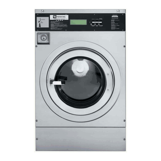
Maytag MFR Series Service Manual

Maytag MFR Series Service Manual

Hide thumbs Also See for MFR Series:
Table of Contents

Advertisement

SeRviCe Manual
Maytag Commercial
MFR Series Washers
MFR INVERTER DRIVE MODELS:
MFR18PD
MFR25PD
MFR30PD,
MFR40PD,
MFR50PD
MFR60PD,
MFR80PD,
TeCHniCal eDuCaTiOn
W10251143
MFR30PN
MFR40PN
MFR60PN
MFR80PN

Advertisement

Table of Contents
loading

Summary of Contents for Maytag MFR Series

  • Page 1 W10251143 SeRviCe Manual Maytag Commercial MFR Series Washers MFR INVERTER DRIVE MODELS: MFR18PD MFR25PD MFR30PD, MFR30PN MFR40PD, MFR40PN MFR50PD MFR60PD, MFR60PN MFR80PD, MFR80PN TeCHniCal eDuCaTiOn...
  • Page 2 This Maytag Service Manual, ”MFR Series Washers” (Part No. W10251143), provides the Commercial Laundry Service Professional with information on the installation, operation, and service of the MFR series washers. For specific information on the model being serviced, refer to the “Installation Instructions,” or “Tech Sheet” provided with the washer.
  • Page 3: Table Of Contents

    TaBle OF COnTenTS Page Equipment & Safety ......................viii Instructions For Using This Manual .................. viii Document links ......................... viii GeneRal ..........................1-1 Washer safety ........................1-1 Model and serial number designations ................1-2 Model & serial number label and wiring diagram location ..........1-3 Model number conversion table ..................
  • Page 4 Page COMpOnenT aCCeSS ......................4-1 Remove softener compartment funnel and siphon ............4-1 Raise the top ........................4-2 Remove facia - PD ......................4-3 Remove facia - PN ......................4-3 Remove stop button - PN ....................4-4 Remove control board - PD ....................4-5 Remove control board &...
  • Page 5 Page Remove AKO inverter - MFR18 & 25 ................4-35 Remove Mitsubishi E500 inverter ..................4-36 Remove Mitsubishi D700 inverter ..................4-38 Remove brake resistor MFR60 & 80 ................4-39 Remove drain valve ......................4-40 Remove temperature sensor .................... 4-42 CaBineT ReMOval ........................
  • Page 6 Page Testing transformer MFR18 & 25 ..................7-17 Testing temperature sensor ....................7-18 Quick Test: ......................... 7-18 DiaGnOSTiCS & TROuBleSHOOTinG ................8-1 Proper grounding and polarization of 120 volt wall outlets for MFR18 & 25 ..... 8-1 MFR30 - 80 power supply ....................8-1 Troubleshooting Mitsubishi inverters ................
  • Page 7 Page Troubleshooting door leaks ....................8-28 Troubleshooting over-fill condition ..................8-29 Verify hinge position - MFR30 - 50 ................... 8-30 WiRinG DiaGRaMS ......................... 9-1 Mitsubishi inverter ......................9-1 MC4 power circuit ......................9-2 MC5 power circuit ......................9-3 MFR18 - 25 MC4 schematic .................... 9-4 MFR18 - 25 MC5 schematic ....................
  • Page 8: Document Links

    inTeRaCTive SeRviCe Manual inSTRuCTiOnS Click the mouse on any topic in the table of contents to go directly to that section. Click the mouse on any link that says (See page ?-?) to go directly to the page referenced. Click the mouse on any button in the links section to open the attached document. This symbol means a video clip is available.
  • Page 9: General

    GeneRal WaSHeR SaFeTy iMpORTanT electrostatic Discharge (eSD) Sensitive electronics ESD problems are present everywhere. ESD may damage or weaken the electronic control assembly. The new control assembly may appear to work well after repair is finished, but failure may occur at a later date due to ESD stress.
  • Page 10: Model And Serial Number Designations

    MODel anD SeRial nuMBeR DeSiGnaTiOnS MODel anD SeRial nuMBeR DeSiGnaTiOnS MODEL nuMBEr BrAnD Maytag riVE & MOunTinG TYPE FR Front Loading / Rigid Mounted Washer FS Front Loading / Free Standing Washer FX Front Loading / Industrial Free Standing Washer...
  • Page 11: Model & Serial Number Label And Wiring Diagram Location

    MODel & SeRial nuMBeR laBel anD WiRinG DiaGRaM lOCaTiOn Location of Wiring Diagram Location of Model & Serial Number Label Inside the Washer in a Pouch MODel nuMBeR COnveRSiOn TaBle MFR18 RF10 MFR25 RF13 MFR30 RF18 MFR40 RF22 MFR50 RF27 MFR60 RF35 MFR80...
  • Page 12 For the first five years from the date of purchase, when this commercial appliance is installed, maintained and operated according to the instructions attached to or furnished with the product, Maytag brand of Whirlpool Corporation (thereafter “Maytag”) will pay for factory specified parts or original equipment manufacturer parts to correct defects in materials or workmanship.
  • Page 13 FOURTH AND FIFTH YEAR LIMITED WARRANTY ON CERTAIN PARTS In the fourth and fifth years form the date of purchase, Maytag will pay for the following washer parts: the outer shell, drum and shaft assembly, inner welded frame, and bearings and seals.
  • Page 14 WaRRanTy On-pReMiSe launDRy (Opl) SaleS pRiOR TO May 2009   ®   ®                          ...
  • Page 15: General User Information

    The US model number indicates the Brand, pertains to the service procedures involved drive type, mounting method, capacity, and in maintaining and servicing Maytag MFR18 control type. through MFR80 PDC and PNC commercial washer models built starting in the third M = Maytag product.
  • Page 16: Dimensions And Components

    DiMenSiOnS anD COMpOnenTS 1. Control panel 2. Door handle 3. Service panel 4. Air relieve 5. Liquid soap hose passing 6. Serial Plate 7. Steam connection 8. Drain connection 9. Earth connection 10. Hot water connection 11. Cold soft water connection 12.
  • Page 17 7 kg 10 kg 13 kg 18 kg 22 kg 27 kg 35 kg Machine capacity 18 lbs 25 lbs 30 lbs 40 lbs 50 lbs 60 lbs 80 lbs 660 mm 660 mm 750 mm 855 mm 855 mm 1100 mm 870 mm 29.5”...
  • Page 18: Technical Specifications 18/25/30/40 Lb. Capacity

    TeCHniCal SpeCiFiCaTiOnS 18/25/30/40 lB. CapaCiTy 3.1. Specifications 18/25/30/40 Lb Capacity 7 kg / 18 lb 10 kg / 25lb 13 kg / 30 lb 18 kg / 40 lb Capacity: Packing: carton box carton box carton box carton box Width 700 mm / 27.6"...
  • Page 19: Technical Specifications 50/60/80 Lb. Capacity

    TeCHniCal SpeCiFiCaTiOnS 50/60/80 lB. CapaCiTy 3.2. Specifications 50/60/80 Lb Capacity Capacity: 22 kg / 50 lb 27 kg / 60lb 35 kg / 80 lb carton box Packing: Crating Crating 935 mm / 36.8" Width 950 mm / 337.4” 1150 mm / 45.3" 1050 mm / 41.3"...
  • Page 20: Tool Set For Rigid Machines

    TOOl SeT FOR RiGiD MaCHineS Tool Set Code H965 518877 Valid for : • 6 - 7 - 10 - 13 - 18 - 27 - 35 kg / 18 - 25 - 30 - 40 - 60 - 80 lb and, •...
  • Page 21: Service Kits To Convert Mfr Coin Drop To Simple Opl

    SeRviCe kiTS TO COnveRT MFR COin DROp TO SiMple Opl SeRviCe kiT 23004091 - for MFR30/40/50/60/80 washers Part Description Pieces Cover of coin box Coin drop cover plate - assembly Nut M4 Washer M4 Washer M4 Plastic washer 4,3x8x5 Central stop wiring Service instruction AMP 155914 Liquid soap supply connector...
  • Page 22: Eprom Chip Version Changes

    epROM CHip veRSiOn CHanGeS MC4 PD EPROM Chip Software #641 MC5 PD EPROM Chip Software #742 Hardware Version 4 Hardware Version 5 Change Releases Change Releases Release Release Version # Changes Date Version # Changes Date 5/12/2004 1.00 First Production inverter models 1.00 First Production 1/25/2010...
  • Page 23: Installation Information

    If severe damage is inflicted on the washer it should be refused. nOTe: The Maytag responsibility for a shipment reaching its destination in satisfactory condition ends with it being delivered to the shipping company in good condition.
  • Page 24: End Of Wash Cycle

    There are 15 pre-programmed wash cycles PN Display with an option to program 99 wash cycle options on the PN models. On the PD models, after the cycle selection is made the proper amount of coins will be required to be entered into the coin drop mechanism.
  • Page 25: To Unlock The Door Manually

    TO unlOCk THe Daily MainTenanCe DOOR Manually iMpORTanT: This procedure should only be • Keep the washer clean at all times. Do not allow residual soap and any cleaners to done by a qualified servicer. remain on the washer cabinet or top for any length of time.
  • Page 26: Convert Coin Washer To Simple Opl

    COnveRT COin WaSHeR TO SiMple Opl Make sure to use plastic washers (Part 6), washers (Part 4,5), and nuts (Part 3) for connecting the coin drop cover plate assembly. Sticker must be tightened very well. Avoid over tighting welded bolts. Electrical Shock Hazard Disconnect power before servicing.
  • Page 27: Invert Water Inlet Valve Screen

    inveRT WaTeR inleT COnveRT FROM 60Hz valve SCReen TO 50Hz OpeRaTiOn Remove the washer hoses if installed. To invert an inlet valve screen, use needle nose pliers to pull it out using a twisting motion. Electrical Shock Hazard Disconnect power before servicing. Replace all parts and panels before operating.
  • Page 28: Troubleshooting Mfr Inlet Hose Leaks

    HOSe leakS For commercial laundry washing machines the water inlet hoses are supplied with the washers from Maytag. These hoses are configured with fittings at each end. At one end is a standard NPT fitting that fits onto faucets in North America, the other end has a European fitting that fits onto the back of the MFR washers.
  • Page 29: Basic Operation

    BaSiC OpeRaTiOn OpeRaTinG COnTROlS The control boards used in the MFRxxPDC While all models use the same control board, coin washers provides electrical power MFR18PDC and MFR25PDC are 120VAC distribution and switching to the operating washers. These two models have a built in components of the washer.
  • Page 30: Cabinet Front Panels

    CaBineT FROnT panelS The cabinet front panels are easily removed The main front panel is secured by bolts by removing a few screws that secure the along the inside lower edge of the control panels to the cabinet side panel edges or in panel (raise the top) and the screws on the the case of the lower service panel, to the front panel.
  • Page 31: Washer Door

    WaSHeR DOOR While there are different door diameters At the 9:00 o’clock position on the left side for each washer model based on the size of the door ring is the door handle and door (capacity) of each model there are several handle lever.
  • Page 32: Door Lock Operation

    DOOR lOCk OpeRaTiOn The MFR line of commercial washer models At the beginning of the cycle, power is also use an electro-mechanical door lock assembly provided to the door lock bi-metal latch in mounted to the outer tub front at the 9:00 the door lock assembly.
  • Page 33: Drain Valve

    DRain valve The drain valve is a motor driven half-ball type The “door locked switch” would change back mechanical valve consisting of: a motor, a to the unlocked position and with the latch bar valve body, shaft (with a water seal), return no longer behind the door handle lever tongue spring and a pivoting half-ball inside the valve the user would be able to pull the door handle...
  • Page 34: Water Inlet Valves

    WaTeR inleT valveS The water inlet valves are mounted to the The water at the inlet (G) pushes against the rear bridge of the washer cabinet and are diaphragm (H). The solenoid plunger (B) and accessed by opening the top cover. Most the spring (A) by themselves are not strong of the MFR washer models will have three enough to overcome the water pressure...
  • Page 35: Brake Resistor - Mfr60 - 80

    BRake ReSiSTOR - MFR60 - 80 The brake resistor is on the left side of the Reconnect the wires to the positive and PR inverter and only on MFR60 and MFR80 terminals. If one of these wires in incorrectly models. The brake resistor prevents over attached to the negative terminal it will voltage on the DC bus.
  • Page 36: Inverter

    The inverter in Maytag commercial washers is Input power to the inverter is supplied via a used mainly as a motor speed control device. contactor (high current relay) that is controlled by the main control board at the front of the By altering the frequency of the current to the washer.
  • Page 37: Motor

    MOTOR TRanSFORMeR The control board step-up transformer is used All MFR washers, that are equipped with only in the MFR18 - 25. This transformer inverter drives, use 3-phase drive motors. provides 230 volts for the control board. The power for these motors comes directly This washer is powered by 120 volts 60Hz from the inverter drive.
  • Page 38: Mfr Pd User Interface Usage In Program Mode

    MFR pD uSeR inTeRFaCe uSaGe in pROGRaM MODe In program mode, the legend in the upper The configuration menu choices are machine right corner of the display shows the functions type, reset defaults, brightness display or load of the buttons. inverter parameters.
  • Page 39: Mfr Pn Control Panel Usage

    MFR pn COnTROl panel uSaGe Turn key in left lid lock to enter program mode. Item 6 is “Load Inverter Parameters”. Press The select cycle screen changes to the main enter, then confirm and enter. The parameters menu screen. will be sent to the inverter drive. Parameters are the limits and proper programming of the inverter itself, to match what the display reads, for the control board programming.
  • Page 40: Chemical Injection Control

    CHeMiCal inJeCTiOn COnTROl Washers built prior to 2007 may not have a Int / Ext chemical injection control signal box. MC5 160ma Power control board washers have the relays and Fast Blow Jumper transformer on the main washer control board, Fuse they used to be on the signal board.
  • Page 41 This does not prove there is power available MC5 Control at the terminals, just that the control board is Board attempting to turn on the relay. The control board tells the relays to turn on via a wiring harness. If the LEDs do not light, and the controls are programmed correctly, the first thing to check is this wiring harness, at both ends, because these LEDs will light up even if...
  • Page 42 Alternately, it is possible to remove three screws from the rear panel that secure the 6 chemical inlet ports, take the port manifold out, and connect chemical feed lines directly to the hoses inside the washer that go directly to the supply box.
  • Page 43: Contactor

    COnTaCTOR The contacts of the relay have a supply side that is directly wired to the incoming power supply, and a working side that is wired to the inverter. This is all single phase 208-240 volt. Three phase is only supplied on the output side of the inverter to the drive motor.
  • Page 44: Coin Drop Acceptor

    COin DROp aCCepTOR The coin drop acceptor is used only in the PD The coin sensor is mounted to a bar located model washers. This is a mechanical coin at the back of the coin acceptor. There is drop assembly with a coin sensor attached. a window period for a coin to pass the coin In normal use, occasional cleaning in hot sensor.
  • Page 45: Component Access

    COMpOnenT aCCeSS ReMOve SOFTeneR COMpaRTMenT Funnel anD SipHOn Open the chemical dispenser lid. When reinserting the siphon cap, realign the fins on the siphon cap with the grooves in the cup assembly. Push the cup assembly toward the front. Siphon Cap Fins Assembly Grooves...
  • Page 46: Raise The Top

    RaiSe THe TOp Lift the top on its hinges. Use the prop rod, mounted inside on the right side panel, to hold the top up. There is a hole in the under flange of the top to insert the prop rod into. Electrical Shock Hazard Prop Rod Hole Disconnect power before servicing.
  • Page 47: Remove Facia - Pd

    ReMOve FaCia - pD ReMOve FaCia - pn Electrical Shock Hazard Electrical Shock Hazard Disconnect power before servicing. Disconnect power before servicing. Replace all parts and panels before Replace all parts and panels before operating. operating. Failure to do so can result in death or Failure to do so can result in death or electrical shock.
  • Page 48: Remove Stop Button - Pn

    ReMOve STOp BuTTOn - pn Remove the screw that secures the stop switch to the back side of the control panel. Lift the releasing lever at the top of the switch and pull the knob off the front of the switch.
  • Page 49: Remove Control Board - Pd

    ReMOve COnTROl BOaRD - pD Pull the board out and to the right. The control board and mounting bracket come out as a unit. To replace the control board, remove the 7 star head screws that secure the control board to the mounting bracket. Electrical Shock Hazard Mounting Panel Disconnect power before servicing.
  • Page 50: Remove Control Board & Membrane Switch - Pn

    ReMOve COnTROl BOaRD & MeMBRane SWiTCH - pn Push on the right hand side of the board, from inside the washer, and slide it to the right to remove the control board membrane switch assembly from the front of the control panel.
  • Page 51: Remove Key Pad - Pd

    ReMOve key paD - pD ReMOve anD ReplaCe epROM CHip Electrical Shock Hazard Electrical Shock Hazard Disconnect power before servicing. Disconnect power before servicing. Replace all parts and panels before Replace all parts and panels before operating. operating. Failure to do so can result in death or Failure to do so can result in death or electrical shock.
  • Page 52: Remove Fuse From Control Board

    ReMOve FuSe FROM ReMOve COnTROl panel COnTROl BOaRD Electrical Shock Hazard Electrical Shock Hazard Disconnect power before servicing. Disconnect power before servicing. Replace all parts and panels before Replace all parts and panels before operating. operating. Failure to do so can result in death or Failure to do so can result in death or electrical shock.
  • Page 53: Remove Coin Drop Mechanism

    ReMOve COin DROp MeCHaniSM To clean the coin drop mechanism, remove the top clip. Open and remove the left side. Remove any dirt or sediment inside halves. Lubricate just the coin return plunger with white lube or grease. Electrical Shock Hazard Disconnect power before servicing.
  • Page 54: Remove Optic Sensor

    ReMOve OpTiC SenSOR Unscrew the connections on the terminal strip behind the optic sensor. Securing Screws Electrical Shock Hazard Disconnect power before servicing. Replace all parts and panels before operating. Failure to do so can result in death or electrical shock. Coin One Raise the top of the washer (See page 4-2).
  • Page 55: Remove Coin Vault

    ReMOve COin vaulT Remove the 7mm nut, flat washer and star washer near the side panel, under the coin vault. Remove the 5/16” hex head bolt from the top edge of the coin vault mounting bracket. 5/16” Hex Electrical Shock Hazard Head Bolt Disconnect power before servicing.
  • Page 56: Remove Washer Top

    ReMOve WaSHeR TOp ReMOve lOWeR SeRviCe panel Electrical Shock Hazard Electrical Shock Hazard Disconnect power before servicing. Disconnect power before servicing. Replace all parts and panels before Replace all parts and panels before operating. operating. Failure to do so can result in death or Failure to do so can result in death or electrical shock.
  • Page 57: Remove The Door

    ReMOve THe DOOR ReMOve HinGe BlOCkS Open the washer door. Remove the door (See left column). Remove two nuts and washers from the Slide the hinge blocks off the hinge pin inside of the door hinge. along with the flat washer with each hinge block.
  • Page 58: Remove Door Handle & Latch

    ReMOve DOOR HanDle & laTCH Open the washer door. If necessary, hold the head of the carriage bolt on the front side of the door with a pair of locking pliers. Release the spring pin on the inside of the door latch.
  • Page 59 ReMOve anD ReplaCe DOOR GlaSS anD GaSkeT MFR18 - 50 Open the washer door. From inside the door, get the lip started at the six o’clock position. From the inside of the door, grasp the gasket and glass at the top edge and peel Make sure the string is hanging out the front the gasket back away from the door to of the door.
  • Page 60: Remove & Install Door Gasket - Mfr60 - 80

    ReMOve & inSTall DOOR GaSkeT - MFR60 - 80 Open the washer door. nOTe: Make sure the head of the M4 bolt is level with the door-frame. Over drilling will remove too much metal from the door Remove the gasket. frame and cause loose screws.
  • Page 61 nOTe: To pull a rubber gasket on the frame it may be necessary to perform this procedure with two people. One holds gasket on the top of the door ring and the second gradually pulls it down to reach around the door ring. The small lip of the rubber gasket must lay flat on the door frame, but will have a tendency to want to roll back under the main part of the gasket...
  • Page 62: Remove Front Panel - Mfr18 & 25

    ReMOve FROnT panel - MFR18 & 25 Loosen completely, but not remove, the four star head screws on the front panel. There are spacers inside to keep the panel from being crushed when the screws are tightened. Electrical Shock Hazard Disconnect power before servicing.
  • Page 63: Remove Front Panel With 90° Rotation - Mfr30 - 80

    ReMOve FROnT panel WiTH 90° ROTaTiOn - MFR30 - 80 Loosen completely, but not remove, the four star head screws on the front panel. There are spacers inside to keep the panel from being crushed when the screws are tightened. Open the washer door.
  • Page 64: Removable Hinge Pin

    ReMOvaBle HinGe pin ReMOve FROnT panel STRaiGHT FORWaRD Remove the door and hinge blocks Alternate procedure of front panel removal (See page 4-13). for locations that will not allow the front panel to be turned 90 degrees on models with a removable hinge pin. For hinges that accept the 6 or 8 millimeter bolts, on all models prior to 2007, tap the hinge pin with a hammer.
  • Page 65: Remove Door Hinge

    ReMOve DOOR HinGe ReMOve DOOR lOCk nO aCCeSS panel Electrical Shock Hazard Electrical Shock Hazard Disconnect power before servicing. Disconnect power before servicing. Replace all parts and panels before Replace all parts and panels before operating. operating. Failure to do so can result in death or Failure to do so can result in death or electrical shock.
  • Page 66 Remove two star head screws on the left When reinstalling the door lock assembly side of the door opening. it is important that the shims stay in place. Put some adhesive on the side of the shim that faces the tub front, press them together to keep the shims in place.
  • Page 67: Remove Door Lock - With Access Panel

    ReMOve DOOR lOCk - WiTH aCCeSS panel Remove the two star head screws from the lock assembly. Electrical Shock Hazard Disconnect power before servicing. Replace all parts and panels before 2 Star Head operating. Screws Failure to do so can result in death or electrical shock.
  • Page 68: Remove Door Lock Mounting Block

    ReMOve DOOR lOCk MOunTinG BlOCk Electrical Shock Hazard Disconnect power before servicing. Replace all parts and panels before operating. Failure to do so can result in death or electrical shock. nOTe: Depending on model and year of production, the front panel may or may not have a door lock access panel.
  • Page 69: Remove Water Inlet Valve Assembly

    ReMOve WaTeR inleT valve aSSeMBly Disconnect the wire connectors. Mark them for correct reassembly. Loosen two 7mm hex head hose clamps Electrical Shock Hazard Twist the hoses and pull them off. Disconnect power before servicing. Replace all parts and panels before Mark the hoses as to which goes to the left operating.
  • Page 70: Remove Chemical Dispenser

    ReMOve CHeMiCal DiSpenSeR Loosen the clamp at the back of the dispenser to remove the vent tube. Loosen the clamp under the dispenser to remove the outlet hose. Electrical Shock Hazard Disconnect power before servicing. Replace all parts and panels before operating.
  • Page 71: Remove Contactor

    ReMOve COnTaCTOR ReMOve TRanSFORMeR MFR18 & 25 Electrical Shock Hazard Electrical Shock Hazard Disconnect power before servicing. Disconnect power before servicing. Replace all parts and panels before Replace all parts and panels before operating. operating. Failure to do so can result in death or Failure to do so can result in death or electrical shock.
  • Page 72: Remove Terminal Block

    ReMOve TeRMinal BlOCk ReMOve BaCk panel Electrical Shock Hazard Electrical Shock Hazard Disconnect power before servicing. Disconnect power before servicing. Replace all parts and panels before Replace all parts and panels before operating. operating. Failure to do so can result in death or Failure to do so can result in death or electrical shock.
  • Page 73: Remove And Reinstall Belts - Mfr25

    ReMOve anD ReinSTall BelTS - MFR25 Reinstall the large belt on the basket pulley and around the smaller front diameter portion of the idler pulley. Electrical Shock Hazard Disconnect power before servicing. Replace all parts and panels before operating. Failure to do so can result in death or electrical shock.
  • Page 74: Remove Belt - Mfr18 & 30 - 80

    ReMOve BelT - MFR18 & 30 - 80 Electrical Shock Hazard Disconnect power before servicing. Replace all parts and panels before operating. Failure to do so can result in death or electrical shock. Remove the back panel (See page 4-28). Reduce tension on the belt by putting pressure on the tensioning device.
  • Page 75: Remove Idler Assembly, Pulley And Bearing - Mfr25

    ReMOve iDleR aSSeMBly, pulley anD BeaRinG - MFR25 To remove the idler pulley, use a snap ring tool to remove the small retainer ring. Bearing Pulley Snap ring Snap Ring Electrical Shock Hazard Disconnect power before servicing. Replace all parts and panels before operating.
  • Page 76: Remove Motor - Mfr18 & 25

    ReMOve MOTOR - MFR18 & 25 On MFR25, springs come off the idler and tensioner easily after the belts are removed. Idler Electrical Shock Hazard Springs Disconnect power before servicing. Replace all parts and panels before operating. Failure to do so can result in death or electrical shock.
  • Page 77: Remove Motor - Mfr30 - 80

    ReMOve MOTOR - MFR30 - 80 Mark the wire position on the wires to be removed, reversing any 2 of the wires will result in a motor turning in the wrong direction. Remove the cover plate and remove 3 nuts that secure the power supply wires to the Electrical Shock Hazard motor.
  • Page 78: Remove Motor Mounting Plate - Mfr30 - 80

    ReMOve MOTOR MOunTinG plaTe - MFR30 - 80 Remove the nut from the bolt and pull the pivot bolt out of the motor mounting plate. Electrical Shock Hazard Disconnect power before servicing. Replace all parts and panels before operating. Failure to do so can result in death or electrical shock.
  • Page 79: Remove Ako Inverter - Mfr18 & 25

    ReMOve akO inveRTeR - MFR18 & 25 Disconnect the ground wire, the incoming power, the motor phase harness in the center, the JP4 connector, and the wiring connections to the interference filter. Clip any wire ties necessary to remove the wire connections.
  • Page 80: Remove Mitsubishi E500 Inverter

    ReMOve MiTSuBiSHi e500 inveRTeR Remove the cover by pushing in the two tabs and pulling down. This gives access to the motor connections on the right side and the input power connections on the left side of the inverter. Remove the small grid supporting the wires. Electrical Shock Hazard Disconnect power before servicing.
  • Page 81 Loosen the lower and remove the two upper flat blade screws that secure the inverter to the washer. Support the inverter when removing the upper screws so it will not fall. Flat Blade Screws Lift inverter up and out. 4-37...
  • Page 82: Remove Mitsubishi D700 Inverter

    ReMOve MiTSuBiSHi D700 inveRTeR Remove the power supply wires. The order of these wire connections is not important. Remove the three wires that go to the motor. The wires are marked 1, 2 and 3. TeCH Tip: Always note the order these Electrical Shock Hazard wires are connected.
  • Page 83: Remove Brake Resistor Mfr60 & 80

    ReMOve BRake ReSiSTOR MFR60 & 80 Disconnect the positive and PR wires from the inverter. Positive (+) Electrical Shock Hazard Disconnect power before servicing. Replace all parts and panels before operating. Failure to do so can result in death or electrical shock.
  • Page 84: Remove Drain Valve

    ReMOve DRain valve Remove the air dome hose and fill hose from the supply box by loosening the clamps and pulling the hoses off. Loosen the hose clamp that secures the inlet hose on the top. Electrical Shock Hazard Inlet Hose Disconnect power before servicing.
  • Page 85 Remove the two 13mm nuts from the valve. The motor closes the flapper valve of the drain when power is applied. A new replacement drain valve will have plugs in the left and right valve openings. Make sure these plugs are knocked out before attaching hoses to the drain valve.
  • Page 86: Remove Temperature Sensor

    ReMOve TeMpeRaTuRe SenSOR Remove the center nut and gently pull the temperature sensor out, use a pair of pliers if it is too tight to pull out by hand. Silicone Electrical Shock Hazard Sealant Disconnect power before servicing. Replace all parts and panels before operating.
  • Page 87: Cabinet Removal

    CaBineT ReMOval ReMOve CaBineT - MFR30 - 80 Remove the temperature sensor at the back of the tub (See page 4-42). If the inverter is an E500 series, unplug the communication cable from the front of the inverter. For D700 model inverters, remove the cover plate from the front of the inverter.
  • Page 88 Remove the cover on the drain valve to Remove the bolts and star washers from disconnect the ground wire, the common the bottom rails of the side panels. and L1 then pull them through to the back. Bundle up the wires and put them outside the cabinet so they don’t get tangled.
  • Page 89 TeCH Tip: Before reinstalling the cabinet onto the washer, the hose from the dispenser, the air hose from the control board and the door latch wiring should excessive Weight Hazard be taped to the top of the tub for easier use two people to move or install reassembly.
  • Page 90: Remove Cabinet - Mfr18 & 25

    ReMOve CaBineT - MFR18 & 25 Unplug door lock wire harness at DL1 by squeezing the locking tab and pulling it off the control board. Cut wire ties that secure door lock cable to the front panel. Electrical Shock Hazard Disconnect power before servicing.
  • Page 91 . Remove three cabinet screws from each side rail at the base of the washer. One from each side accessible from the back, and two from each side accessible from the excessive Weight Hazard front. use two people to move or install heavy parts.
  • Page 92 ---- nOTeS ----...
  • Page 93: Tubs, Baskets, Bearings & Seals

    TuBS, BaSkeTS, BeaRinGS & SealS ReMOve & ReinSTall BaSkeT pulley - MFR18 & 25 Install the center bolt M12x50, #518933, into the center of the basket shaft. Attach the 3 arm puller, #518936, to the tool #518929 with the pushing bolt seated in the center bolt.
  • Page 94: Remove Trunnion And Basket - Mfr18 & 25

    ReMOve TRunniOn anD BaSkeT - MFR18 & 25 Mark the location of the anti-rotation strap on the tub ring. Top Bolt Electrical Shock Hazard Disconnect power before servicing. Replace all parts and panels before operating. Failure to do so can result in death or electrical shock.
  • Page 95 The bolt that secures the anti-rotation strap Use a standard two or three arm puller to to the tub ring and the base support, and push the basket shaft out of the trunnion the matching bolt on the opposite side, are and back plate assembly.
  • Page 96: Remove Trunnion & Replace Bearings - Mfr18 & 25

    ReMOve TRunniOn & ReplaCe BeaRinGS - MFR18 & 25 Remove the tub seal from the back plate. Remove the stainless steel back plate and the remaining bolts from the tub ring. Remove the iron back plate and the tub ring. Electrical Shock Hazard Disconnect power before servicing.
  • Page 97 To remove the rear bearings, load the tool Clean any debris or corrosion out of the #518878 with the sleeve #518896 and push corner between the bearing seat and the bushing #518905 or #518893. Insert the shoulder with a flat blade screwdriver. tool through the front bearing.
  • Page 98 To replace first of the front bearings, brush To replace first of the rear bearings, brush a thin layer of Loctite® 603 on the bearing a thin layer of Loctite® 603 on the bearing seat of the bearing housing closest to the seat of the bearing housing closest to the shoulder.
  • Page 99: Remove & Replace Axial Seal - Mfr18 & 25

    ReMOve & ReplaCe axial Seal - MFR18 & 25 Use a Scotch-Brite™ pad to clean surface of seal holder removing any dirt or residue without removing any seal holder material, that would change the fitting dimension. Electrical Shock Hazard Disconnect power before servicing. Replace all parts and panels before operating.
  • Page 100: Remove & Replace Counter-Face Ring Mfr18, 25, 30, 40, 50, 80

    ReMOve & ReplaCe COunTeR-FaCe RinG MFR18, 25, 30, 40, 50, 80 Apply a second thin layer of Scotch-Clad™ 776 to the same area. Avoid applying any to the bearing seat or shoulder. Install the counter-face ring, rubber side toward the basket, until the ring rests on the counter-face ring seat of the basket shaft.
  • Page 101: Reinstall Trunnion Assembly - Mfr18 & 25

    ReinSTall TRunniOn aSSeMBly - MFR18 & 25 Locate the mark made to indicate the top of the tub ring. Lay the tub ring on the spokes, mark down, aligning the mark with the ventilation holes. Electrical Shock Hazard Disconnect power before servicing. Replace all parts and panels before operating.
  • Page 102 Replace the rubber tub seal, aligning all 12 Use a rigid or right angle socket wrench. holes. Place a nut in the socket, a lock washer and a flat washer. Reinstall this combination on nOTe: If reinstalling the original tub seal each of the six stainless steel bolts through make sure to orient the marks made to the spokes.
  • Page 103 Once the back plate is centered, turn the Remove center bolt from the basket shaft. center bushing and listen for any contact to make sure everything is centered. Place bearing support #518916 or #518915 onto the center of the trunnion. First tighten two opposing bolts, torqued Place extension tool #518913 onto the to 7 foot pounds, to secure the centering...
  • Page 104 Verify that the front shoulder of the basket Reinstall the anti-rotation bracket and shaft is almost equal with the inner race of reinstall a flat washer and nut on the bolt the rear bearing, between 0 and .02 inch coming through the frame and tub ring from (0 and 0.5mm) the inside out.
  • Page 105 If it is not centered, begin tightening the Tighten the bolts around the tub ring to a bolt directly behind narrowest gap. Move final torque of 15 foot pounds. Make sure to next lower bolt, and continue in that to check the bolts again at the bottom after direction around the tub ring.
  • Page 106: Remove Trunnion Assembly - Mfr30

    ReMOve TRunniOn aSSeMBly - MFR30 To remove the trunnion, remove six 13mm nuts and washers from the bolts that secure the trunnion to the tub. Two of the nuts are positioned under the trunnion. nOTe: Do not push threaded bolts towards tub, because they are sealed from behind and pushing them could cause a leak.
  • Page 107 Use a standard 2 arm puller to remove Place the wood block, #518918, on the the trunnion. Make sure the 2 hooks are frame to support the basket shaft. This properly positioned in the trunnion and the wood block is 2 3/8” square. push bolt is positioned in the middle of the center bolt.
  • Page 108: Remove & Replace Bearings - Mfr30

    ReMOve & ReplaCe BeaRinGS - MFR30 To remove the front bearing, assemble tool #518878 with sleeve #518896 and push bushing #518894. Insert tool from rear of bearing housing. Install bearing cup #518895, push bearing and cog nut. Use lever bars #514759 to press the bearing out of the bearing housing into bearing cup.
  • Page 109 To install the front bearing into the bearing To install rear bearing into bearing housing, housing, place a thin film of Loctite® 603 make sure the bearing seat is clean and around the front bearing seat in the bearing place a thin film of Loctite® 603 around housing, not on the bearing.
  • Page 110: Remove & Replace Axial Seal And Counter-Face Ring - Mfr30

    ReMOve & ReplaCe axial Seal anD COunTeR-FaCe RinG - MFR30 Use a flat blade screwdriver to remove the rubber seal and counter-face ring which are glued in place on the basket shaft. Counter- face Ring Electrical Shock Hazard Disconnect power before servicing. Replace all parts and panels before operating.
  • Page 111 To install the seal, place the new axial Apply a continuous bead, about 1mm in seal with the carbon ring into tool #518961. size, of Loctite® 5203™ on the flange of the Apply a thin layer of Scotch-Clad™ 776 to seal holder just inside the bolt holes.
  • Page 112: Reinstall Trunnion Assembly - Mfr30

    ReinSTall TRunniOn aSSeMBly - MFR30 Slide the trunnion onto the basket shaft. Use the threaded rod to lift the basket shaft and remove the wood block. Continue holding the weight of the basket shaft and slide the trunnion forward as far as possible against the back of the drum, matching the bolts to the holes in the trunnion.
  • Page 113: Remove & Reinstall Spin Basket - Mfr30

    ReMOve & ReinSTall Spin BaSkeT - MFR30 Press the trunnion onto the basket shaft using a 20mm hex key to hold the press tool. Use the bar wrench #514695 to tighten the threaded rod nut until it is tight. Remove the press tools. Verify the position of the trunnion.
  • Page 114 Remove the clips around the front shell of Use a standard 2 arm puller to push the the drum with a screwdriver. Make sure not basket out with. Be sure the 2 hooks are to bend the clips when removing them. properly positioned in the trunnion and the push bolt is positioned in the middle of the center bolt.
  • Page 115 Replace the nut on threaded rod #518912. Replace the front panel of the drum Install push bearing tool #514691 and by aligning the marks made during bearing support #518914. Thread the disassembly. Use a rope or wire to pull the assembled tool into the hole of the basket hooks over the edge of the front shell all shaft.
  • Page 116: Remove The Basket - Mfr40 & 50

    ReMOve THe BaSkeT - MFR40 & 50 Mark the bolt holes that have tabs on them for wiring harness wire ties. Electrical Shock Hazard Disconnect power before servicing. Replace all parts and panels before Wire Tie Tab operating. Marks Failure to do so can result in death or electrical shock.
  • Page 117 There is a rear ring, a back plate which is Using a lift if possible, connect the lift to black, and four shims that may or may not the pulling eye. come out. Shims have notches where the bolts come through. It is not necessary to remove the shims unless they are falling off.
  • Page 118: Remove And Install Bearings - Mfr40 - 50

    ReMOve anD inSTall BeaRinGS - MFR40 - 50 Insert the center bolt, #518940, into the threaded hole of the shaft in the center of the pulley. First tighten it by hand, then tighten the bolt by wrench until just a few threads are left showing on the bolt.
  • Page 119 Install a standard two arm puller to the Remove the seal plate and then the seal trunnion with the pushing bolt centered on from the seal holder. the center bolt. Seal Plate Seal Holder Remove the seal holder by prying it off the bearing housing.
  • Page 120 Clean the bearing areas of any sealant Remove the front bearing (SKF 6310). and corrosion with a Scotch-Brite™ pad. Assemble the tool #518878 with the sleeve #518896 and push bushing #518899 or #518984. Insert the tool from the rear of the bearing housing.
  • Page 121 To install the front bearing into the bearing To install the rear bearing into bearing housing, place a thin film of Loctite® 603 housing, make sure bearing seat is clean around the front bearing seat in the housing, and place a thin film of Loctite® 603 around not on the bearing.
  • Page 122 Reinstall the snap ring, into the groove Visually check that the seal is completely in the bearing housing, in front of the front inserted into the holder and sits against the bearing. back wall of the seal holder. Clean any dirt and old sealant in and around the seal area, as well as the threads of the 6 bolts.
  • Page 123 With two people, lift the back plate trunnion Apply a continuous bead, about 1mm in assembly, guide it onto the basket shaft. size, of Loctite® 5203™ around the outside edge of the seal holder. Remove center bolt from the basket shaft, if present.
  • Page 124 TeCH Tip: When reinstalling the basket Install the bar wrench, #514695, onto the pulley, put the tolerance ring on the shaft pushing nut. Block the trunnion and back and secure it with a wire tie to keep it tight plate assembly from turning using the lever to the shaft, apply a small amount of grease bar, #514760, in the center of one of the on the outside of the tolerance ring.
  • Page 125 Use the bar wrench #514695 to turn the Use lever bar #514759 to block the pulley nut of the threaded rod to push the pulley from moving while tightening. onto the shaft. Remove the lever bar and bar wrench. Support Use a hex key to remove the threaded rod Extension and tools.
  • Page 126: Remove Tub From Frame - Mfr40 & 50 (All Other Models Are Similar)

    ReMOve TuB FROM FRaMe - MFR40 & 50 (all OTHeR MODelS aRe SiMilaR) Loosen the clamp that connects the hose from the tub to the drain valve. Remove air hose from hanger on the tub. Drain Hose Electrical Shock Hazard Clamp Disconnect power before servicing.
  • Page 127: Remove & Replace Bearing Assembly - Mfr60

    ReMOve & ReplaCe BeaRinG aSSeMBly - MFR60 Electrical Shock Hazard Disconnect power before servicing. Replace all parts and panels before operating. V-Belts Failure to do so can result in death or Pry Board electrical shock. Under Motor To remove the basket pulley, block it from moving using the lever bar, #514759.
  • Page 128 Attach the puller tool, #518936, to the pulley To remove the bearing housing, use a spokes with the pushing bolt in the middle 24mm socket, with a breaker bar, to remove of the M16 center bolt. the two top and two bottom M16x50 bolts that secure bearing housing to the frame.
  • Page 129 Turn the pushing bolt until the trunnion is To remove the seal ring, remove the wood about flush with the end of the shaft. block and place the seal ring removal tool, #518970, onto the shaft, while centering the pushing bolt in center of M16 center bolt. #518970 Put the wood block back on the two lower Mark the top of the housing with tape,...
  • Page 130 Loosen the hex bolts on the sleeve of the To re-seat the seal, slide the seal sleeve, removal tool and remove the wood block, #518981, onto the shaft up to the seal ring. tool, and seal ring from the shaft. Place the push bearing tool, #514691, onto the threaded rod, #518910.
  • Page 131 To remove the rear bearing, load the tool Use lever bars #514759 to tighten the cog #518878 with the sleeve #518896, and nut until the rear bearing is pressed, from push bushing #518894. the inside out, into the bearing cup. Tool #518878 To remove the front bearing and seal holder, load the tool #518878 with sleeve...
  • Page 132 Insert the push bushing, #518884, flat To reassemble the radial main shaft seals side down on the seal. Make sure it is into the seal holder, load the tool #518878 concentric with the seal. with the sleeve #518896. Place the smooth side of one seal down Bearing Cup onto the larger push bushing, #518888.
  • Page 133 Tighten the cog nut by hand, pushing the Make sure bearing holder is not damaged. seals together. Some grease can squeeze out, just wipe clean after removing the seal holder from the tool assembly. Bearing Holder Apply Loctite® 603, with a brush, to the rear bearing seat of the housing.
  • Page 134 Turn the cog nut, with lever bars #514759, Load the tool #518878 with the sleeve until the bearing is seated firmly against #518905, push bushing #518886 with the the bearing holder. From the outside, the front bearing seated on it. Insert the tool bearing should appear almost flush, just a through the front of the bearing housing.
  • Page 135 Turn the cog nut with lever bars #514759, Put a thin film of grease on the bearings until it is tight and the seal holder is in its and the shaft. proper place. Make sure the part of the bearing housing The seal holder has a shoulder and will previously marked top is facing the top.
  • Page 136 Remove the bar wrench and use a 17mm Clean shaft end with a dry, clean cloth. hex key to remove threaded rod and tools. To replace the tolerance ring, place it 2 Side Bolt on the shaft and apply a small amount of Locations grease on the outside of the tolerance ring.
  • Page 137 109. To replace the v-belt, use a pry bar or 103. Use the bar wrench #514695 to turn the board to lift the motor up a little. nut of the threaded rod to push the pulley onto the shaft. 110. Place the inner v-belt around the motor Push Bearing Bar Wrench...
  • Page 138: Remove Tub Front Panel - Mfr80

    ReMOve TuB FROnT panel - MFR80 Loosen, to the end of the bolt, both 13mm nuts on both outer band clamps that secure the tub front panel to the tub. Electrical Shock Hazard Disconnect power before servicing. Replace all parts and panels before Outer Band operating.
  • Page 139: Remove Basket Pulley - Mfr30 - 80

    ReMOve BaSkeT pulley - MFR30 - 80 Place tool #518936, or similar puller, on the pulley. Make sure the center pushing bolt of the puller is in the middle of the center bolt in the shaft. Turn the center pushing bolt until the pulley is almost off the shaft.
  • Page 140: Remove Spin Basket - Mfr80

    ReMOve Spin BaSkeT - MFR80 Remove the tub front panel (See page 6-46) Place a wood shim(s) between the outer tub and the spin basket to keep it close to level during removal. Spin Basket Electrical Shock Hazard Disconnect power before servicing. Replace all parts and panels before Wood Shims operating.
  • Page 141 Remove the four M16 hex bolts from the 4 One person should push guide rod toward bearing housing corners. the inside of the washer from the back. Loosen the top and bottom bolts but not Another person can pull the basket out of remove them.
  • Page 142: Remove & Replace Bearing Assembly - Mfr80

    ReMOve & ReplaCe BeaRinG aSSeMBly - MFR80 Use a strong putty knife and hammer to separate the tub-back from the trunnion. nOTe: These parts are held together with a semi-permanent gasket material similar to Loctite® 5203™. Do not use a silicone product for this because it needs to be removable.
  • Page 143 Set it down with the holder out of the bearing housing. back down. nOTe: Maytag suggests that the entire trunnion assembly be replaced (skip to step 38). When an entire trunnion is not available, it will be necessary to continue from here.
  • Page 144 nOTe: Make sure not to misshapen the Striking the thorn will need to be done grease ring when prying it out in exact centered strokes, with a sledge hammer, to avoid having the bearing shift position while pushing it out of the bearing Remove as much grease as possible by housing.
  • Page 145 To install the rear bearing into the bearing To install the front bearing into the bearing housing, make sure the bearing seat is housing, make sure the bearing seat is clean and free of grease. Place a thin film clean and free of grease. of Loctite®...
  • Page 146 Pack grease into the both sides of the front To install the seal, apply a thin layer of bearing and front side of the rear bearing. Scotch-Clad™ 776, to just the outside edge of the seal. Avoid covering the entire nOTe: Video was shot without grease to surface of the seal.
  • Page 147 Immediately check that there is no space Apply a bead of Loctite® 5203™, or between the bottom of the seal and the seal similar product, to the threads of the four holder seat. If space is found, use tool seal holder mounting screws. Secure all #518858 to again apply force to seat the four screws.
  • Page 148 Work from corner to corner reinstalling Tighten the bolts around the center ring by bolts. Put them in just snug, not tight. working on opposing sides. Center Ring Install the counter-face ring on the basket When 6 bolts are snug, begin tightening shaft (See page 6-8).
  • Page 149 Slide the guide rod through the bearing When fully seated, the shoulder on the and screw it into the center hole of the shaft should line up almost flush with the shaft. inner race of the rear bearing. If there is too much or not enough difference in the placement, the seal will not be able to be Insert the lever bar and tighten the guide...
  • Page 150 ---- nOTeS ---- 6-58...
  • Page 151: Component Testing

    COMpOnenT TeSTinG Electrical Shock Hazard Disconnect power before servicing. Replace all parts and panels before operating. Failure to do so can result in death or electrical shock. TeSTinG & RepaiRinG WaTeR inleT valveS Depending on the model there are various Turn off power and remove the wire numbers of water inlet valves and they may be connectors from the solenoid and check...
  • Page 152: Inlet Valve-Stem Assembly Parts

    inleT valve-STeM aSSeMBly paRTS The stem assembly consists of a diaphragm, a plunger with a rubber tip and a return spring. Rubber Tip Electrical Shock Hazard Disconnect power before servicing. Replace all parts and panels before operating. Diaphragm Plunger Spring Failure to do so can result in death or electrical shock.
  • Page 153: Testing Door Lock Components From Door Lock Wire Harness Plug

    Electrical Shock Hazard Disconnect power before servicing. Replace all parts and panels before operating. Failure to do so can result in death or electrical shock. TeSTinG DOOR lOCk COMpOnenTS FROM DOOR lOCk WiRe HaRneSS pluG Disconnect the door lock wire harness To test the Door Lock Switches: connector at the door lock assembly.
  • Page 154: Testing Door Lock Components From Control Board

    Electrical Shock Hazard Disconnect power before servicing. Replace all parts and panels before operating. Failure to do so can result in death or electrical shock. TeSTinG DOOR lOCk COMpOnenTS FROM COnTROl BOaRD Disconnect the door lock wire harness To test the Door Closed Switch: connector from the control board at DL1.
  • Page 155: Testing Contactor

    TeSTinG COnTaCTOR WARNING WARNING DANGER Electrical Shock Hazard Electrical Shock Hazard Only authorized technicians should Disconnect power before servicing. perform diagnostic voltage Replace all parts and panels before measurements. operating. After performing voltage Failure to do so can result in death or electrical shock.
  • Page 156 The second cause of the contactor contacts The fourth reason for a contactor not passing not closing is worn or burnt contacts within the voltage through it would be that the coil is not contactor. getting voltage to it. To check continuity of the connecting wire: Check for proper line voltage (208-240V) at the terminals marked L1, L2, and L3 on the...
  • Page 157: Testing Inverters

    TeSTinG inveRTeRS WARNING WARNING DANGER Electrical Shock Hazard Electrical Shock Hazard Disconnect power before servicing. Only authorized technicians should perform diagnostic voltage Replace all parts and panels before measurements. operating. Failure to do so can result in death or After performing voltage electrical shock.
  • Page 158 CHeCk DC BuSS vOlTaGe Remove the cover of the inverter to gain Check DC Buss voltage between Positive access to the motor connections on the (+) and Negative (-) terminals. right side and the input power connections on the left side. Unplug washer or disconnect power.
  • Page 159 akO & MOTOR TeST Unplug washer or disconnect power. If motor did not run: Connect a power test cord to L1 & Neutral • Check the 10 amp fuse located on the (N) contacts of the motor control board. control board, either visually or with an ohmmeter.
  • Page 160 MOTOR pHaSe TeST Unplug washer or disconnect power. Check phase C by disconnecting the Yellow or Orange wire at the inverter. Plug in motor test cord into a wall outlet. If Remove the two screws that secure the the motor operates with a slight growling inverter to the base of the washer.
  • Page 161 MOTOR WinDinG CHeCk Unplug washer or disconnect power. Check that all six motor terminals are secure and at the same height in the motor terminal. Replace motor if any terminals To gain access to the inverter control board, are pressed into the motor. perform steps 2 - 8 of Motor Phase Test (See page 7-10).
  • Page 162: Testing Brake Resistor

    Electrical Shock Hazard Disconnect power before servicing. Replace all parts and panels before operating. Failure to do so can result in death or electrical shock. TeSTinG BRake ReSiSTOR Remove power from washer and wait 10 Set the ohmmeter to at least a 200,000 ohm scale.
  • Page 163: Testing Motors

    Electrical Shock Hazard Disconnect power before servicing. Replace all parts and panels before operating. Failure to do so can result in death or electrical shock. TeSTinG MOTORS OTHeR COMpOnenT ReSiSTanCe CHaRT MFR18 - 25 motors have 3 motor winding Component: Resistance: wires (black, white, brown) and 2 gray wires (tachometer circuit) –...
  • Page 164: Testing Washer Control Board

    Electrical Shock Hazard Disconnect power before servicing. Replace all parts and panels before operating. Failure to do so can result in death or electrical shock. TeSTinG WaSHeR COnTROl BOaRD Of All the parts that are returned to Whirlpool First, look at the power supply connector to Corporation for testing, that have been found see if it is connected properly on the control to have No Apparent Defect (NAD), it is by far...
  • Page 165 If there are lines forming in the display it is After an EPROM chip is installed and the most likely just the display that is failing and it power is restored, the display should be could be replaced with a spare display. lighting up.
  • Page 166: Testing Pd Key Pad

    Electrical Shock Hazard Disconnect power before servicing. Replace all parts and panels before operating. Failure to do so can result in death or electrical shock. TeSTinG pD key paD Unplug washer or disconnect power. Set the ohmmeter to the R X 1 scale. Set digital ohmmeters to lowest scale.
  • Page 167: Testing Pn Key Pad

    Electrical Shock Hazard Disconnect power before servicing. Replace all parts and panels before operating. Failure to do so can result in death or electrical shock. TeSTinG pn key paD TeSTinG TRanSFORMeR MFR18 & 25 To test a particular button, find the point on the The Transformer is located next to the Matrix that is just below and left of the letter contactor in the control tray.
  • Page 168: Testing Temperature Sensor

    Electrical Shock Hazard Disconnect power before servicing. Replace all parts and panels before operating. Failure to do so can result in death or electrical shock. TeSTinG TeMpeRaTuRe SenSOR The temperature sensor cable is connected at QuiCk TeST: the upper right hand side of the control board •...
  • Page 169: Diagnostics & Troubleshooting

    DiaGnOSTiCS & TROuBleSHOOTinG WARNING MFR30 - 80 pOWeR Supply The power supply required for all MFR30 - 80 washers is 208 - 240 VAC single phase. Electrical Shock Hazard The model serial plate will proclaim washers Plug into a grounded 3 prong outlet. will function with 3 phase power.
  • Page 170: Troubleshooting Mitsubishi Inverters

    MCG programming manual concerning nOTe: Use only Maytag genuine the “Configuration” menu. Make sure the replacement parts, especially in the motor model type of the washer match the settings and inverter circuits.
  • Page 171 Having this information, the technician can Fault Codes: check to see if the contactor engages and sends power to the inverter when a cycle If, in the course of the operation of the washer, is started, and if not, determine the reason, the inverter or washer control board determine repair the problem, and put the washer there is a problem in the inverter drive or...
  • Page 172 There are two LEDs on the back of the control TeCH Tip: if there are more than a few board that show communication between Maytag mulit-load washers that are being the control board and the inverter. The LEDs maintained and / or serviced, Maytag...
  • Page 173: Troubleshooting Ako Inverters

    TROuBleSHOOTinG akO inveRTeRS TeCH Tip: If the inverter is showing a code that indicates a problem on the output side of the inverter, disconnect the wiring completely from the motor power circuit side of the inverter and run the washer as a test, if the code is gone the problem could be in Electrical Shock Hazard the motor circuit.
  • Page 174: Remove Inverter Cooling Fan

    ReMOve inveRTeR COOlinG Fan nOTe: This is a 24VDC fan. If the fan were to quit running the drive would run hotter shortening the life of the drive. If the drive runs too hot, it will shut itself down and give a code.
  • Page 175: Inverter "Do Not's

    Do not replace the Maytag drive motor with Do not fail to clean the inverter’s cooling another brand motor or with a motor from fins and fan on a regular basis. Replace another supplier.
  • Page 176: Troubleshooting At Control Board

    TROuBleSHOOTinG aT COnTROl BOaRD Control Boards for MFR, MFX, and MFS washers may all look the same and have connections marked on them that are not used by the product that you may be working on. Follow the wiring diagram for the model being serviced to know what is connected and where. The following pages will help identify the working connectors on MFR wahers.
  • Page 177: Mc5 Control Boards

    MC5 COnTROl BOaRDS Opl Control Board RS485 Fuse Coin Control Board RS485 Fuse...
  • Page 178: Diagnosing The Control Board

    DiaGnOSinG THe COnTROl BOaRD Correct software version on the chip? (read the software version in the service mode) Electrical Shock Hazard Disconnect power before servicing. Replace all parts and panels before operating. Failure to do so can result in death or electrical shock.
  • Page 179: Troubleshooting Display Problems

    TROuBleSHOOTinG DiSplay pROBleMS If the display is illuminated, and the washer If the display is still not illuminated, remove will not start, look at the 3-wire power the control board (See page 4-5). Remove connector at P1 on the control board. four #1 star head screws from the back Looking at it from the side of the washer, of the control board that hold the display...
  • Page 180: R1 - Harness Plug

    The corresponding wires on R1 plug are shown and the readings are shown below: Segments If replacing a failed control board that has a good display, Maytag recommends removing the display and saving it for possible use on another washer with a Pin Wire # Resistance Connects To display board problem.
  • Page 181: Dl1 - Door Lock Connector

    Dl1 - DOOR lOCk COnneCTOR TTl y1 - SeRial COM2 Wire Wire Component +5VDC Grey Bimetal Bimetal Lock Coil Lock Coil Door Closed Switch Door Closed Switch D1 - MC4 12vDC Tap Purple Door Locked Switch MC5 24vDC Tap Door Locked Switch Unlock Coil Wire Unlock Coil...
  • Page 182: K1 - Pd Key Pad Connector

    Q1 - MC5 pn - CHeMiCal Supply k1 - pD key paD COnneCTOR Wire Signal Cycle Contact Contact Button Black Supply 1 Whites Supply 2 Colors Pink Supply 3 Bright Colors Brown Supply 4 Perm Press Yellow Supply 5 Quick Wash Green Supply 6 Delicates &...
  • Page 183: Troubleshooting Motor

    TROuBleSHOOTinG MOTOR To check the motor mechanically one could remove the drive belt(s), and then manually spin the rotor by grasping the motor pulley and giving it a good spin. The motor should sound nice and smooth as it turns. If the motor exhibits a grinding sound during this test, it may be time to have the motor bearings serviced or have a new motor...
  • Page 184: Troubleshooting Belt Tension - Mfr40 - 50

    TROuBleSHOOTinG BelT TenSiOn - MFR40 - 50 Loosen the clamp that secures the overflow hose and remove it from the drain connector. Overflow Hose Clamp Electrical Shock Hazard Disconnect power before servicing. Replace all parts and panels before operating. Failure to do so can result in death or electrical shock.
  • Page 185 Drill a 7mm (0.27”) hole in the motor plate. Drill a 7mm hole (0.27”) where measured and marked in the previous step on the L-profile of the frame. Install new spring in hole in frame and in the motor plate. Mark the frame for the new spring hole in the frame.
  • Page 186: Troubleshooting Drain Valves

    TROuBleSHOOTinG DRain valveS To check if foreign objects may be lodged in the valve, or inspect the seal lip of the valve, open the washer door and, using a flashlight, look through the holes in the bottom of the basket to view the inlet side of the drain valve.
  • Page 187 If the plug was left in place on the air dome A common problem would be scale buildup side, the symptom would be that the washer on the seal that the ball comes up against. would overfill. This is the first thing to check Sometimes it will harden and this is not for an overfill error.
  • Page 188: Troubleshooting Door Lock

    TROuBleSHOOTinG DOOR lOCk NOTE: When checking components from the control board make sure the connector is disconnected from the control board (See page 7-3). To troubleshoot the door lock in its location on the washer, it is necessary to to access Electrical Shock Hazard the lock mechanism, (See page 4-23).
  • Page 189: Remove Door Locked Switch

    Frequently, during the service procedure, this very small copper washer gets lost or misplaced. Maytag recommends that spare washers be kept on the service truck. This copper washer does Two Star not come when ordering a new solenoid.
  • Page 190: Remove Latch Bar

    ReMOve laTCH BaR To remove latch bar, disconnect the spring from the latch bar. Electrical Shock Hazard Disconnect power before servicing. Replace all parts and panels before operating. Failure to do so can result in death or electrical shock. The latch bar moves back and forth in slot near point A, is retracted by spring at point B, pivots on a pin at C and activates the door lock microswitch at point D when the...
  • Page 191: Remove Bimetal

    ReMOve BiMeTal Lift the bimetal from the door lock assembly remove two wire connectors. Electrical Shock Hazard Two Wire Disconnect power before servicing. Connectors Replace all parts and panels before operating. Failure to do so can result in death or electrical shock.
  • Page 192: Remove Blocking Bar

    ReMOve BlOCkinG BaR ReMOve DOOR ClOSeD SWiTCH Electrical Shock Hazard Electrical Shock Hazard Disconnect power before servicing. Disconnect power before servicing. Replace all parts and panels before Replace all parts and panels before operating. operating. Failure to do so can result in death or Failure to do so can result in death or electrical shock.
  • Page 193: Remove Door Lock Solenoid

    ReMOve DOOR ReMOve DOOR lOCk SOlenOiD unlOCk SOlenOiD Electrical Shock Hazard Electrical Shock Hazard Disconnect power before servicing. Disconnect power before servicing. Replace all parts and panels before Replace all parts and panels before operating. operating. Failure to do so can result in death or Failure to do so can result in death or electrical shock.
  • Page 194: Verification Of Door Gasket Pressure

    veRiFiCaTiOn OF DOOR GaSkeT pReSSuRe If any contact exists, add a small manual vertical force (maximum 5 pounds) to the door to attempt to eliminate the contact. Electrical Shock Hazard Disconnect power before servicing. Replace all parts and panels before operating.
  • Page 195 Verify the distance from the chalk marks to Move the door slowly to the closed position the door glass. with handle closed, using one finger, until the latch touches the stainless steel roller of the door lock, then release the pressure If the distance is greater on top or on the against the door.
  • Page 196: Troubleshooting Door Leaks

    TROuBleSHOOTinG DOOR leakS Most door leaks can be contributed to debris on the door seal or tub front lip. Clean these areas regularly and check this first if the washer leaks out the front of the door. Electrical Shock Hazard Disconnect power before servicing.
  • Page 197: Troubleshooting Over-Fill Condition

    TROuBleSHOOTinG OveR-Fill COnDiTiOn Second would be a blocked or leaking air hose that runs from the Water Level Switch on the Control Board down to the Drain Valve. This hose should be inspected for rub marks, cracks or pin-holes. It should also be checked at the lower end for debris in the hose that connects at the Drain Valve.
  • Page 198: Verify Hinge Position - Mfr30 - 50

    veRiFy HinGe pOSiTiOn - MFR30 - 50 Mark a line at the right side of the hinge to use as a guide to keep the hinge parallel during adjustment. Line Next To Hinge Electrical Shock Hazard Disconnect power before servicing. Replace all parts and panels before operating.
  • Page 199: Wiring Diagrams

    WiRinG DiaGRaMS MiTSuBiSHi inveRTeR Inverter Drive shielded cable Contactor (CM1) (data) RS485 Communication (data) Motor Control Board * 3 phase machines only Fig. 1...

Table of Contents