Advantech WISE-6610 Series User Manual
Indsutrial lorawan gateway
Hide thumbs
Also See for WISE-6610 Series:
- User manual (55 pages) ,
- User manual (100 pages) ,
- User manual (64 pages)
Table of Contents
Advertisement
Advertisement
Table of Contents

Related Manuals for Advantech WISE-6610 Series


Summary of Contents for Advantech WISE-6610 Series
- Page 1 User Manual WISE-6610 Series Indsutrial LoRaWAN Gateway...
- Page 2 No part of this manual may be reproduced, copied, translated or transmitted in any form or by any means without the prior written permission of Advantech Co., Ltd. Information provided in this manual is intended to be accurate and reliable. How- ever, Advantech Co., Ltd.
- Page 3 Technical Support and Assistance Visit the Advantech web site at www.advantech.com/support where you can find the latest information about the product. Contact your distributor, sales representative, or Advantech's customer service center for technical support if you need additional assistance.
- Page 4 If any item does not accord with the table, please contact your dealer immediately. 1 x Indsutrial LoRa private gateway 1 x DIN-Rail mounting bracket and screws 1 x Wall-mounting bracket WISE-6610 Series User Manual...
- Page 5 The sound pressure level at the operator's position according to IEC 704-1:1982 is no more than 70 dB (A). DISCLAIMER: This set of instructions is given according to IEC 704-1. Advan- tech disclaims all responsibility for the accuracy of any statements contained herein. WISE-6610 Series User Manual...
- Page 6 Der arbeitsplatzbezogene Schalldruckpegel nach DIN 45 635 Teil 1000 beträgt 70dB(A) oder weiger. Haftungsausschluss: Die Bedienungsanleitungen wurden entsprechend der IEC-704-1 erstellt. Advantech lehnt jegliche Verantwortung für die Richtigkeit der in diesem Zusammenhang getätigten Aussagen ab. WISE-6610 Series User Manual...
- Page 7 Always disconnect the power from the device before servicing it. Before plugging a cable into any port, discharge the voltage stored on the cable by touching the electrical contacts to the ground surface. WISE-6610 Series User Manual...
-
Page 8: Table Of Contents
Contents Chapter Product Overview ....... 1 Specifications.................... 2 Hardware Views..................3 1.2.1 Front View..................3 1.2.2 Rear View ..................3 1.2.3 Top View..................3 1.2.4 System LED Panel................ 4 Dimensions ....................4 Chapter Gateway Installation ......5 Warning..................... 6 Installation Guideline................. 7 Installing the Gateway................ - Page 9 3.6.7 Update Firmware ................ 66 3.6.8 Reboot ..................67 Chapter Configuration in Typical Situations ...........68 Enabling the LoRaWAN and Network Server ......... 69 Changing the Raw LoRa Data Format ............ 86 Node-RED Setup ..................88 SmartSwarm 243 User Manual...
- Page 10 List of Figures Figure 1.1 Front View ........................3 Figure 1.2 Rear View........................3 Figure 1.3 Top View ........................3 Figure 1.4 System LED Panel ......................4 Figure 2.1 Installing the Antenna....................8 Figure 2.2 Positioning the Antenna ....................8 Figure 2.3 Wall Mount Installation ....................
- Page 11 User Modules > LoRaWAN Gateway > LoRaWAN Server ......... 61 Figure 3.54 User Modules > LoRaWAN Gateway > LoRaWAN Server (https) ......62 Figure 3.55 User Modules > LoRaWAN Gateway > Advantech Application ........62 Figure 3.56 Administration > Users ....................63 Figure 3.57 Administration >...
-
Page 12: Product Overview
Chapter Product Overview... -
Page 13: Specifications
Certifications EN61000-4-2, Level 3 EN61000-4-3, Level 3 EN61000-4-4, Level 3 EN61000-4-5, Level 3 EN61000-4-6, Level 3 EN61000-4-12, Level 3 EN61000-4-11, voltage dip: 70% Shock IEC60068-2-27 Free Fall IEC60068-2-32 Vibration IEC60068-2-6 WISE-6610 Series User Manual... -
Page 14: Hardware Views
Description DIN-Rail holes Screw holes (2) used in the installation of a DIN rail clip. 1.2.3 Top View Figure 1.3 Top View Item Description Wall mounting holes Screw holes (4) used in the installation on wall. WISE-6610 Series User Manual... -
Page 15: System Led Panel
1.2.4 System LED Panel LED Name LED Color Description Green Green Green Dimensions mm [inch] 140 [5.51] 150 [5.90] 125.40 [4.94] I / O Figure 1.4 System LED Panel WISE-6610 Series User Manual... -
Page 16: Gateway Installation
Chapter Gateway Installation... -
Page 17: Warning
Caution! The installation, replacement, or service of the device must be Only be performed by trained and qualified personnel. Caution! Ultimate disposal of this product should be handled according to local and national regulations WISE-6610 Series User Manual... -
Page 18: Installation Guideline
Make sure airflow around the switch and respective vents is unrestricted. With- out proper airflow the switch can overheat. To prevent performance degredation and damage to the switch, make sure there is clerance at the top and bottom and around the exhaust vents. WISE-6610 Series User Manual... -
Page 19: Installing The Gateway
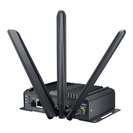
I / O Figure 2.1 Installing the Antenna Position the antenna for optimal signal strength. Note! The location and position of the antenna is crucial for effective wireless connectivity I / O Figure 2.2 Positioning the Antenna WISE-6610 Series User Manual... -
Page 20: Wall Mounting
If necessary first drill pilot holes. Drill four holes over the four marked locations on the wall. On concrete, it is recommended to install wall sinks Align the SmartSwarm over the installation location on the wall. Secure the SmartSwarm with screws (Ø 5.0 mm). Figure 2.3 Wall Mount Installation WISE-6610 Series User Manual... -
Page 21: Din Rain Mounting
DIN rail clip. If seated correctly, the bottom of the DIN rail should be fully inserted in the release tab. DIN rail clip DIN rail DIN rail clip release tab Figure 2.5 Installing the DIN-Rail Mounting Kit WISE-6610 Series User Manual... -
Page 22: Figure 2.6 Correctly Installed Din Rail Kit
Push down on the top of the DIN rail clip release tab with your finger. As the clip releases, lift the bottom of the SmartSwarm, as shown in the following illustra- tion. Figure 2.7 Removing the DIN-Rail WISE-6610 Series User Manual... -
Page 23: Connecting The Gateway To Ethernet Port
Connect the other end to a wall outlet. The LEDs light when the device is connected to the power source I / O Figure 2.9 Installing the Power Cable The following table show the color lines definition: Yellow Black Gray WISE-6610 Series User Manual... -
Page 24: Managing Gateway
Chapter Managing Gateway... -
Page 25: Access Interface
To access the login window, connect the device to the network, see “Connecting the Gateway to Ethernet Port” on page 12. When WISE-6610 Series is first installed, make sure the network environment is configured to enable access to the device. -
Page 26: Recommended Practices
Changing Default Password In keeping with good management and security practices, it is recommended that you change the default password as soon as the WISE-6610 Series is functioning and setup correctly. The following details the necessary steps to change the default password. -
Page 27: Status
EUI-64 format link local IPv6 address derived from MAC address of the interface. It is generated and assigned the first time the interface is used (e.g. cable is connected, Mobile WAN connecting, etc.). To access this page, click Status > General. Figure 3.3 Status > General WISE-6610 Series User Manual... -
Page 28: Network
The DHCP server assigns each device an IP address, subnet mask, default gateway (IP address of device) and DNS server (IP address of device). DHCPv6 server is supported. To access this page, click Status > DHCP. Figure 3.5 Status > DHCP WISE-6610 Series User Manual... -
Page 29: Ipsec
Invalid hostname format. Hostname exists, but not under specified username. No update performed yet. DynDNS record is already up to date. DynDNS record successfully update. DNS error encountered. DynDNS server failure. WISE-6610 Series User Manual... -
Page 30: System Log
To access this page, click Status > System Log. Figure 3.8 Status > System Log The following example (figure) shows how to send syslog information to a remote server at 192.168.2.115 on startup. Figure 3.9 Example Program Syslogd Start with the Parameter -R WISE-6610 Series User Manual... -
Page 31: Configuration
If you configure both IPv4 and IPv6, other network devices will choose the communication protocol. Configuration items and IPv6 to IPv4 differences are described in the tables below. WISE-6610 Series User Manual... -
Page 32: Figure 3.10 Configuration > Lan
IPv6 notation in IPv6 column. Shortened IPv6 notation is supported. Subnet Mask / Prefix Specifies a Subnet Mask for the IPv4 address. In the IPv6 column, fill in the Prefix for the IPv6 address - number in range 0 to 128. WISE-6610 Series User Manual... - Page 33 If IPv6 column is filled in, the DHCPv6 server is used - it is dual stack IPv4 and IPv6. Note! Do not to overlap ranges of static allocated IP addresses with addresses allocated by the dynamic DHCP server. IP address conflicts and incorrect network function can occur if you overlap the ranges. WISE-6610 Series User Manual...
-
Page 34: Figure 3.11 Ipv6 Address With Prefix Example
The decimal value of the Subnet ID of the Ethernet interface. delegation Maximum value depends on the Subnet ID Width. Subnet ID Width The maximum Subnet ID Width depends on your Site Prefix - it is the remainder to 64 bits. WISE-6610 Series User Manual... -
Page 35: Figure 3.12 Ipv4 Dynamic Dhcp Network Topology
3.4.1.3 IEEE 802.1X Authentication To prevent unauthorized radios from accessing data transmitting over wireless transmission, WISE-6610 Series provides rock solid security settings. Navigate to Configuration > LAN and locate Enable IEEE 802.1X Authentication. Item Description Enable IEEE 802.1X Tick the radio button to enable the authentication function. -
Page 36: Figure 3.13 Lan Configuration For A Dynamic Network Typology
The address is allocated for 600 seconds (10 minutes). The client with the MAC address 01:23:45:67:89:ab has the IP address 192.168.1.10. The client with the MAC address 01:54:68:18:ba:7e has the IP address 192.168.1.11. Figure 3.14 IPv4 Dynamic and Static DHCP Network Topology WISE-6610 Series User Manual... -
Page 37: Figure 3.15 Lan Configuration For An Ipv4 Dynamic And Static Dhcp Network Topology
The range of dynamic allocated IPv6 addresses is from 2001:db8::1 to 2001:db8::ffff. The address is allocated for 600 second (10 minutes). The device is still accessible via IPv4 (192.168.1.1). Figure 3.16 IPv6 Dynamic DHCP Server Network Topology WISE-6610 Series User Manual... -
Page 38: Figure 3.17 Lan Configuration For An Ipv6 Dynamic Dhcp Server Network Topology
Figure 3.17 LAN Configuration for an IPv6 Dynamic DHCP Server Network Topology WISE-6610 Series User Manual... -
Page 39: Nat
Item Description Public Port Public port for the translation rule. Private Port Private port for the translation rule. Type Protocol type - TCP or UDP. Server IP Address IP address where the router forwards incoming data. WISE-6610 Series User Manual... - Page 40 De- fault Server IPv4/IPv6 Address field. The router can for- ward incoming data from a GPRS to a computer with the assigned IP address. Default Server IP The IP address. Address WISE-6610 Series User Manual...
-
Page 41: Figure 3.19 Topology For Nat Configuration Example 1
192.168.1.2:80 socket behind the router when accessing the IP address 10.0.0.1:81 from the Internet. If you send a ping request to the public IP address of the router (10.0.0.1), the router responds as usual (not forwarding). And since the Send all WISE-6610 Series User Manual... -
Page 42: Figure 3.21 Topology For Nat Configuration Example 2
Figure 3.21 Topology for NAT Configuration Example 2 Figure 3.22 NAT Configuration for Example 2 WISE-6610 Series User Manual... -
Page 43: Openvpn
The device allows you to create up to four OpenVPN tunnels. IPv4 and IPv6 dual stack is supported. To access this page, click Configuration > OpenVPN. Figure 3.23 Configuration > OpenVPN > 1st Tunnel Item Description Description Specifies the description or name of tunnel. WISE-6610 Series User Manual... - Page 44 NAT Rules Activates/deactivates the NAT rules for the OpenVPN tunnel: not applied - NAT rules are not applied to the tunnel. applied - NAT rules are applied to the OpenVPN tunnel. WISE-6610 Series User Manual...
-
Page 45: Figure 3.24 Topology Of Openvpn Configuration Example
SSH - run the openvpnd --help command. Example: OpenVPN Tunnel Configuration in IPv4 Network Figure 3.24 Topology of OpenVPN Configuration Example OpenVPN tunnel configuration: Configuration Protocol UDP Port 1194 1194 WISE-6610 Series User Manual... -
Page 46: Ipsec
Note! If you specify the protocol and port information in the Local Protocol/Port field, then the device encapsulates only the packets matching the settings. WISE-6610 Series User Manual... -
Page 47: Figure 3.25 Configuration > 1St Tunnel
Figure 3.25 Configuration > 1st Tunnel WISE-6610 Series User Manual... - Page 48 - The encryption and hash algorithm are selected automatically. manual - The encryption and hash algorithm are defined by the user. IKE Encryption Encryption algorithm - 3DES, AES128, AES192, AES256. IKE Hash Hash algorithm - MD5, SHA1, SHA256, SHA384 or SHA512. WISE-6610 Series User Manual...
- Page 49 User FQDN (for example, director@companyname.cz) The certificates and private keys have to be in the PEM format. Use only certificates containing start and stop tags. The random time, after which the device re-exchanges new keys is defined as follows: WISE-6610 Series User Manual...
-
Page 50: Gre
GRE is an unencrypted protocol. GRE via IPv6 is not supported. To open the GRE Tunnel Configuration page, click GRE in the Configuration section of the main menu. The GRE tunnel function allows you to create an unencrypted WISE-6610 Series User Manual... -
Page 51: Figure 3.27 Configuration > Gre > 1St Tunnel
Specify the same key on both devices, otherwise the device drops received packets. Note! The GRE tunnel does not pass through NAT. The changes in settings will apply after pressing the Apply button. WISE-6610 Series User Manual... -
Page 52: L2Tp
To open the L2TP Tunnel Configuration page, click L2TP in the Configuration section of the main menu. The L2TP tunnel function allows you to create a password protected connection between 2 LAN networks. The device activates the tunnels after you mark the Create L2TP tunnel check box. WISE-6610 Series User Manual... -
Page 53: Figure 3.29 Configuration > L2Tp
The mask of the network behind the remote side of the tunnel. Mask Username Username for the L2TP tunnel login. Password Password for the L2TP tunnel login. Example: L2TP Tunnel Configuration Figure 3.30 Topology of L2TP Tunnel Configuration Example WISE-6610 Series User Manual... -
Page 54: Pptp
IP address of the remote side of the tunnel. Remote Subnet Address of the network behind the remote side of the tunnel. Remote Subnet The mask of the network behind the remote side of the tunnel. Mask WISE-6610 Series User Manual... -
Page 55: Services
Remote Access service account at www.dyndns.org. Register the custom domain (third-level) and account information specified in the configuration form. You can use other services, too - see the table below, Server item. To open the DynDNS Configuration page, click DynDNS in the main menu. WISE-6610 Series User Manual... -
Page 56: Figure 3.33 Configuration > Services > Dyndns
IPv4 - IPv4 protocol is used only (default). IPv6 - IPv6 protocol is used only. IPv4/IPv6 - IPv4 and IPv6 dual stack is enabled. Example: DynDNS client configuration with the domain company.dyndns.org: Figure 3.34 DynDNS Configuration Example WISE-6610 Series User Manual... -
Page 57: Figure 3.35 Configuration > Services > Http
IPv4 address, IPv6 address or domain name of secondary NTP Server server. Timezone Specifies the time zone where you installed the device. Daylight Saving Time Activates/deactivates the DST shift. No - The time shift is inactive. Yes - The time shift is active. WISE-6610 Series User Manual... -
Page 58: Figure 3.37 Example Of Ntp Configuration
Enable the SNMP agent check box. Sending SNMP traps to IPv6 address is supported. To access this page, click Configuration > Services > SNMP. Figure 3.38 Configuration > Services > SNMP Item Description Name Designation of the device. WISE-6610 Series User Manual... - Page 59 Identifier. This identifier consists of a progression of numbers separated by a point. The shape of each OID is determined by the identifier value of the parent element and then this value is complemented by a point and current number. So it is obvious WISE-6610 Series User Manual...
-
Page 60: Figure 3.39 Oid Basic Structure
(OID 1.3.6.1.4.1.248.40.1.3.3) or about the power voltage (OID 1.3.6.1.4.1.248.40.1.3.4). For binary inputs and output, the following range of OID is used: Description .1.3.6.1.4.1.30140.2.3.1.0 Binary input BIN0 (values 0,1) .1.3.6.1.4.1.30140.2.3.2.0 Binary output OUT0 (values 0,1) .1.3.6.1.4.1.30140.2.3.3.0 Binary input BIN1 (values 0,1) WISE-6610 Series User Manual... -
Page 61: Figure 3.40 Snmp Configuration Example
Remote SNMP agent field. The dialog displayed the internal variables in the MIB tree after entering the IP address. Furthermore, you can find the status of the internal variables by entering their OID. WISE-6610 Series User Manual... -
Page 62: Figure 3.42 Configuration > Services > Smtp
SSH connection. Use the email command with the following parameters: -t: e-mail address of the receiver -s: subject, enter the subject in quotation marks -m: message, enter the subject in quotation marks -a: attachment file WISE-6610 Series User Manual... -
Page 63: Scripts
Note! Any changes to the Startup Script will take effect the next time the device is power cycled or rebooted. This can be done with the Reboot button in the Administration section, or by SMS message. WISE-6610 Series User Manual... -
Page 64: Figure 3.45 Example Of A Startup Script
The changes in settings will apply after pressing the Apply button. Also you need to reboot the device to make Up/Down Script work. To access this page, click Configuration > Scripts > Up/Down IPv4 or Up/Down IPv6. WISE-6610 Series User Manual... -
Page 65: Automatic Update
If the Enable automatic update of firmware option is checked, the device will look for a new firmware file and update its firmware if necessary. WISE-6610 Series User Manual... -
Page 66: Figure 3.47 Configuration > Automatic Update
Firmware update can cause incompatibility with the user modules. It is recommended that you update user modules to the most recent version. Information about the user modules and the firmware compatibility is at the beginning of the user module's Application Note. WISE-6610 Series User Manual... -
Page 67: Customization
Figure 3.48 Example of Automatic Update 1 Example 2: Automatic Update Based on MAC In the following example the device checks for new firmware or configuration each day at 1:00 a.m. An example is given for the WISE-6610 Series device with MAC address 00:11:22:33:44:55. ... -
Page 68: Figure 3.50 User Modules
Linux kernel (for example SmsBE and PoS Configuration). It is best to update user modules to the most recent version. Information about the user module and the firmware compatibility is at the beginning of the user module's Application Note. WISE-6610 Series User Manual... -
Page 69: Figure 3.51 User Modules > Lorawan Gateway > Mqtt And Lorawan
Enter a variable (1 to 65535) to designate the listening port. Listen Port LoRaWAN Network Enter a variable (1 to 65535) to designate the HTTP port. Server HTTP Port LoRaWAN Network Enter a variable (1 to 65535) to designate the HTTPS port. Server HTTPS Port WISE-6610 Series User Manual... - Page 70 Click Save to save the values. Restore Click Restore to restore the values. With MQTT and LoRa configured, pair and modify the node settings, see Node Control. 3.5.1.2 Licenses To download the LoRa license, click the Licenses on the Router menu. WISE-6610 Series User Manual...
-
Page 71: Figure 3.52 User Modules > Lorawan Gateway > Lorawan Status
The LoRaWAN Gateway Settings menu displays. Under Router menu, click LoRaWAN Status. The LoRaWAN Gateway Settings menu displays listing Basic, Channel, and Live Up Stream status information. Figure 3.52 User Modules > LoRaWAN Gateway > LoRaWAN Status WISE-6610 Series User Manual... -
Page 72: Figure 3.53 User Modules > Lorawan Gateway > Lorawan Server
The LoRaWan Server is a ready-to-use solution, which includes a web-based user interface, providing the components needed to build networks. To access this page, click User Modules > LoRaWAN Gateway > LoRaWAN Server. Figure 3.53 User Modules > LoRaWAN Gateway > LoRaWAN Server WISE-6610 Series User Manual... -
Page 73: Figure 3.54 User Modules > Lorawan Gateway > Lorawan Server (Https)
3.5.1.7 Return to Router The main menu is accessible through the Return to Router function. To return the WISE-6610 Series to the main menu, click Customization > User Modules > LoRaWAN Gateway > Return to Router. WISE-6610 Series User Manual... -
Page 74: Administration
Specifies the password for the corresponding user. Confirm Password Confirms the password you specified above. Note! Ordinary users are not able to access device via Telnet, SSH or SFTP. Read only FTP access is allowed for these users. WISE-6610 Series User Manual... -
Page 75: Change Profile
Warning! The default password of the device is root for the root user. To maintain the security of your network change the default password. You can not enable remote access to the device for example, in NAT, until you change the password. Figure 3.58 Administration > Change Password WISE-6610 Series User Manual... -
Page 76: Set Real Time Clock
To navigate to the directory containing the configuration file (.cfg) you wish to load on the device, use the Browse button. To access this page, click Administration > Restore Configuration. Figure 3.60 Administration > Restore Configuration WISE-6610 Series User Manual... -
Page 77: Update Firmware
Firmware update can cause incompatibility with the user modules. It is recommended to update user modules to the most recent version. Information about user module and firmware compatibility is at the beginning of the user module's Application Note. WISE-6610 Series User Manual... -
Page 78: Reboot
3.6.8 Reboot To reboot the device select the Reboot menu item and then press the Reboot button. To access this page, click Administration > Reboot. Figure 3.62 Administration > Reboot WISE-6610 Series User Manual... -
Page 79: Chapter 4 Configuration In Typical Situations
Chapter Configuration in Typical Situations... -
Page 80: Enabling The Lorawan And Network Server
Enabling the LoRaWAN and Network Server Login WISE-6610 Series. See “Access Interface” on page 14. Go to Customization > User Modules. A list of available devices display. Click on the target LoRaWAN Gateway. Figure 4.1 Customization > User Modules The Settings menu displays. In LoRaWAN Radio Enable, click the drop-down menu to enable LoRaWAN function. -
Page 81: Figure 4.3 Lorawan Gateway > Mqtt And Lorawan
In LoRaWAN Network Server Setting, click the drop-down menu to enable LoRaWAN network server. In MQTT Broker Enable, click the drop-down menu to enable MQTT broker. Figure 4.3 LoRaWAN Gateway > MQTT and LoRaWAN Click Save to save the configuration. WISE-6610 Series User Manual... -
Page 82: Figure 4.4 Lorawan Gateway > Lorawan Server
The LoRaWAN Network Server does not support IE or EDGE browser. Figure 4.4 LoRaWAN Gateway > LoRaWAN Server Click Infrastructure > Gateways to enter the Gateways List page. Click Create to add a new gateway. Figure 4.5 LoRaWAN Server > Infrastructure > Gateways WISE-6610 Series User Manual... -
Page 83: Figure 4.6 Lorawan Server > Infrastructure > Gateways > Create
Click Submit to save the values and update the screen. Click Infrastructure > Networks to enter the Networks List page. By default, the WISE-6610 Series pre-configures the network to support EU868, AU915, AS923 and US902. Figure 4.7 LoRaWAN Server > Infrastructure > Networks... -
Page 84: Figure 4.8 Lorawan Server > Infrastructure > Network > Create > General
Click Submit to save the values and update the screen. In the General tab, follow the table below when configuring a new network: Parameter EU868 US902 CN779 EU433 AU915 CN580 AS923 KR920 IN865 RU864 Coding Rate RX1 Join Delay(s) WISE-6610 Series User Manual... -
Page 85: Figure 4.9 Lorawan Server > Infrastructure > Network > Create > Adr
Max EIRP (dBm) Enter a value to specify the EIRP used in your region. Max Power Enter a value to define the first TX Power item. Min Power Enter a value to define the last TX Power item. WISE-6610 Series User Manual... -
Page 86: Figure 4.10 Lorawan Server > Infrastructure > Network > Create > Channel
Max Data Rate: Enter a value to define the highest data rate allowed in this channel. Enter the global value of the ADR tab if it's not specified. Submit Click Submit to save the values and update the screen. WISE-6610 Series User Manual... -
Page 87: Figure 4.11 Lorawan Server > Backends > Handlers
Click Backends > Handlers to enter the Handlers List page. The WISE-6610 Series handler is created by default. The LoRaWAN data comes with the item with the Field in the handler settings. Figure 4.11 LoRaWAN Server > Backends > Handlers... -
Page 88: Figure 4.12 Lorawan Server > Backends > Handlers > Create
Enter the string to extract additional data fields from the uplink frame. See Figure 4.13 for references. Parse Event Enter the string to be forwarded to the backend connector. Build Downlink Enter the string to create a downlink frame based on backend data fields. WISE-6610 Series User Manual... -
Page 89: Figure 4.13 Parse Uplink Sample
LoRaWAN data. For example, data comes with the handler rule should be saved to the MQTT broker or websocket. The broker and websocket on the WISE-6610 Series is enabled by default. The uplink from the sensor node comes with the MQTT topic is uplink/{devaddr} and the downlink topic is out/{devaddr}. -
Page 90: Figure 4.15 Lorawan Server > Backends > Connectors > Create
Enter a string to define the template for parsing the topic of received messages, e.g. in/{devaddr}. This can be used to obtain a DevEUI, DevAddr or a device group that receives a given downlink. Enabled Check to allow a temporarily disable on an existing connector. WISE-6610 Series User Manual... -
Page 91: Figure 4.16 Lorawan Server > Devices > Profiles
Name Enter the name of the profile. Network Click the drop-down menu to select the network. Application Click the drop-down menu to select the application in use. App Identifier Enter the name of the application ID. WISE-6610 Series User Manual... -
Page 92: Figure 4.18 Lorawan Server > Devices > Profiles > Create > Adr
Enter a value to define the set of channels. The channels are given as a comma-separated list of interfaces, e.g. 0-2 for EU, 0-71 for the whole US band, or 0-7,64 for the first US sub-band. WISE-6610 Series User Manual... -
Page 93: Figure 4.19 Lorawan Server > Devices > Activated (Nodes)
Click Create to add a new LoRaWAN node (ABP) along with its Devaddr, APPkey and NwkKey. Figure 4.20 LoRaWAN Server > Devices > Activated (Nodes) > Create Item Description DevAddr Enter the name of the node. Profile Click the drop-down menu to select the profile for the node. WISE-6610 Series User Manual... -
Page 94: Figure 4.21 Lorawan Server > Devices > Commissioned
Enter the AppKey for the device. Last Join Enter a value to define the timestamp of the last successful Join request. Node Enter the corresponding node. Submit Click Submit to save the values and update the screen. WISE-6610 Series User Manual... -
Page 95: Figure 4.23 Lorawan Server > Received Frames
Click Received Frames to enter the Received Frames page and check the received messages. Figure 4.23 LoRaWAN Server > Received Frames Since the MQTT broker on the WISE-6610 series is enabled by default, you can subscribe the MQTT "#" on 192.168.1.1 to receive the LoRaWAN node mes- sages. -
Page 96: Figure 4.25 Mqtt Subscription
Figure 4.25 MQTT Subscription Click Infrastructure > Events to enter the Events List page to view the events. Figure 4.26 LoRaWAN Server > Infrastructure > Events WISE-6610 Series User Manual... -
Page 97: Changing The Raw Lora Data Format
Changing the Raw LoRa Data Format This function parses and shows the raw data from an Advantech LRPv2 LoRa node. Note! WISE-6610 series models does not parse data from a non-Advantech LoRa node through the Advantech Application function. Note! All the foregoing settings must be configured before using this function. -
Page 98: Figure 4.29 User Modules > Lorawan Gateway > Mqtt And Lorawan
Figure 4.30 LoRaWAN Server > Activated (Nodes) Edit the LoRa Node and enter Advantech in the App Arguments field. The Advantech application server will deal with the raw data based on the info and list the real data on the Advantech Application page. -
Page 99: Node-Red Setup
Not only the data will be shown on the Advantech Application page, if you would like to apply the data to other software applications, you can also subscribe Topic “#” or direct Topic “Advantech/+/data” from the WISE-6610 MQTT server. Figure 4.32 Applying Data to Other Software Applications Node-RED Setup Go to Customization >... - Page 100 No part of this publication may be reproduced in any form or by any means, electronic, photocopying, recording or otherwise, without prior written permis- sion of the publisher. All brand and product names are trademarks or registered trademarks of their respective companies. © Advantech Co., Ltd. 2018...
Need help?
Do you have a question about the WISE-6610 Series and is the answer not in the manual?
Questions and answers