Table of Contents
Advertisement
Quick Links
Advertisement
Table of Contents

Related Manuals for Advantech WISE6610N


Summary of Contents for Advantech WISE6610N
- Page 1 User Manual WISE-6610 Series Indsutrial LoRaWAN Gateway...
- Page 2 No part of this manual may be reproduced, copied, translated or transmitted in any form or by any means without the prior written permission of Advantech Co., Ltd. Information provided in this manual is intended to be accurate and reliable. How- ever, Advantech Co., Ltd.
- Page 3 This transmitter must not be co-located or operating in conjunction with any other antenna or transmitter. Technical Support and Assistance Visit the Advantech web site at www.advantech.com/support where you can find the latest information about the product. Contact your distributor, sales representative, or Advantech's customer service center for technical support if you need additional assistance.
- Page 4 Warnings, Cautions and Notes Warning! Warnings indicate conditions, which if not observed, can cause personal injury! Caution! Cautions are included to help you avoid damaging hardware or losing data. e.g. There is a danger of a new battery exploding if it is incorrectly installed. Do not attempt to recharge, force open, or heat the battery.
- Page 5 Safety Instructions Read these safety instructions carefully. Keep this User Manual for later reference. Disconnect this equipment from any DC outlet before cleaning. Use a damp cloth. Do not use liquid or spray detergents for cleaning. For plug-in equipment, the power outlet socket must be located near the equip- ment and must be easily accessible.
- Page 6 Der arbeitsplatzbezogene Schalldruckpegel nach DIN 45 635 Teil 1000 beträgt 70dB(A) oder weiger. Haftungsausschluss: Die Bedienungsanleitungen wurden entsprechend der IEC-704-1 erstellt. Advantech lehnt jegliche Verantwortung für die Richtigkeit der in diesem Zusammenhang getätigten Aussagen ab. WISE-6610 Series User Manual...
- Page 7 Safety Precaution - Static Electricity Static electricity can cause bodily harm or damage electronic devices. To avoid dam- age, keep static-sensitive devices in the static-protective packaging until the installa- tion period. The following guidelines are also recommended: Wear a grounded wrist or ankle strap and use gloves to prevent direct contact to the device before servicing the device.
-
Page 8: Table Of Contents
Contents Chapter Product Overview ....... 1 Specifications.................... 2 Hardware Views..................3 1.2.1 Front View..................3 1.2.2 Rear View ..................3 1.2.3 Top View..................3 1.2.4 System LED Panel................ 4 Dimensions ....................4 Chapter Gateway Installation ......5 Warning..................... 6 Installation Guideline................. 7 Installing the Gateway................ - Page 9 3.6.7 Update Firmware ................ 66 3.6.8 Reboot ..................67 Chapter Configuration in Typical Situations ...........68 Enabling the LoRaWAN and Network Server ......... 69 Changing the Raw LoRa Data Format ............ 86 Node-RED Setup ..................88 SmartSwarm 243 User Manual...
- Page 10 List of Figures Figure 1.1 Front View ........................3 Figure 1.2 Rear View........................3 Figure 1.3 Top View ........................3 Figure 1.4 System LED Panel ......................4 Figure 2.1 Installing the Antenna....................8 Figure 2.2 Positioning the Antenna ....................8 Figure 2.3 Wall Mount Installation ....................
- Page 11 User Modules > LoRaWAN Gateway > LoRaWAN Server ......... 61 Figure 3.54 User Modules > LoRaWAN Gateway > LoRaWAN Server (https) ......62 Figure 3.55 User Modules > LoRaWAN Gateway > Advantech Application ........62 Figure 3.56 Administration > Users ....................63 Figure 3.57 Administration >...
-
Page 12: Product Overview
Chapter Product Overview... -
Page 13: Specifications
Specifications Specifications Description WSN Support Standard LoRaWAN Frequency 868/915 MHz ANT Connector RP-SMA Female connector x 1 LAN Interface Ethernet 10/100 Mbps, auto MDI/MDIX Connector RJ45 x 1 Protection 1.5-kV built-in magnetic isolation protection Digital I/O Port Type Digital input on voltage: 2.7 ~ 36 V Port Connector 4-way Molex moni-fit connector General... -
Page 14: Hardware Views
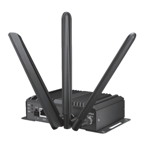
Hardware Views 1.2.1 Front View I / O WISE-6610 LoRa Figure 1.1 Front View Item Description System LED panel See “System LED Panel” on page 4 for further details. I/O (Power socket) Connect cabling for power. ETH port RJ45 x 1 Antenna connector Connector for antenna. -
Page 15: System Led Panel
1.2.4 System LED Panel LED Name LED Color Description Green Green Green Dimensions mm [inch] 140 [5.51] 150 [5.90] 125.40 [4.94] I / O Figure 1.4 System LED Panel WISE-6610 Series User Manual... -
Page 16: Gateway Installation
Chapter Gateway Installation... -
Page 17: Warning
Warning Warning: Before working on equipment that is connected to power lines, remove any jewelry (including rings, necklaces, and watches). Metal objects can heat up when connected to power and ground, which can cause serious burns or weld the metal object to the terminals. -
Page 18: Installation Guideline
Caution! To prevent the system from overheating, do not operate it in an area that exceeds the maximum recommended ambient temperature of: 70°C (158°F). Caution! If the switch is to be installed in a hazardous location, ensure that the DC power source is located away from the vicinity of the switch. Caution! The installation of the equipment must comply with all national and local electrical codes. -
Page 19: Installing The Gateway
Installing the Gateway 2.3.1 Installing Antenna Connect the antenna by screwing the antenna connectors in a clockwise direc- tion. I / O Figure 2.1 Installing the Antenna Position the antenna for optimal signal strength. Note! The location and position of the antenna is crucial for effective wireless connectivity I / O Figure 2.2 Positioning the Antenna... -
Page 20: Wall Mounting
2.3.2 Wall Mounting Locate the area to install and mark the four screw locations. It is suggested to place the device on the installation location and use the mounting locations to mark the location of the screw holes). If necessary first drill pilot holes. Drill four holes over the four marked locations on the wall. -
Page 21: Din Rain Mounting
2.3.3 DIN Rain Mounting 2.3.3.1 Installing the DIN Rail Mounting Kit Align the DIN rail clip with the rear of SmartSwarm. Secure the DIN rail clip and the SmartSwarm with screws. Figure 2.4 Wall Mount Installation Position the rear panel of the SmartSwarm directly in front of the DIN rail, mak- ing sure that the top of the DIN rail clip hooks over the top of the DIN rail, as shown in the following illustration. -
Page 22: Figure 2.6 Correctly Installed Din Rail Kit
See the following figure demonstrating the correct position of a completed DIN installation. Figure 2.6 Correctly Installed DIN Rail Kit 2.3.3.2 Removing the DIN Rail Mounting Kit Ensure that power is removed from the SmartSwarm, and disconnect all cables and connectors from the front panel of the SmartSwarm. Push down on the top of the DIN rail clip release tab with your finger. -
Page 23: Connecting The Gateway To Ethernet Port
Connecting the Gateway to Ethernet Port 2.4.1 RJ45 Ethernet Cable Wiring For RJ45 connectors, data-quality, twisted pair cabling (rated CAT5 or better) is rec- ommended. The connector bodies on the RJ45 Ethernet ports are metallic and con- nected to the GND terminal. For best performance, use shielded cabling. Shielded cabling may be used to provide further protection. -
Page 24: Managing Gateway
Chapter Managing Gateway... -
Page 25: Access Interface
Access Interface To access the login window, connect the device to the network, see “Connecting the Gateway to Ethernet Port” on page 12. When WISE-6610 Series is first installed, make sure the network environment is configured to enable access to the device. Your computer and the device must be on the same network subnet to allow them to establish a network connection. -
Page 26: Recommended Practices
Recommended Practices One of the easiest things to do to help increase the security posture of the network infrastructure is to implement a policy and standard for secure management. This practice is an easy way to maintain a healthy and secure network. After you have performed the basic configurations on your switches, the following is a recommendation which is considered best practice policy. -
Page 27: Status
Status 3.3.1 General Selecting the General item will open a screen displaying a summary of basic information about the device and its activities. This page is also displayed when you login to the web interface. Information is divided into several sections, based upon the type of device activity or the properties area: Mobile Connection, Primary LAN, Peripheral Ports and System Information. -
Page 28: Network
3.3.2 Network To view information about the interfaces and the routing table, open the Network item in the Status menu. To access this page, click Status > Network. Figure 3.4 Status > Network 3.3.3 DHCP Information about the DHCP server activity is accessible via DHCP item. The DHCP server provides automatic configuration of the client devices connected to the device. -
Page 29: Ipsec
3.3.4 IPsec Selecting the IPsec option in the status menu of the web page will bring up the infor- mation for any IPsec Tunnels that have been established. If the tunnel has been built correctly, the screen will display IPsec SA established (highlighted in red in the figure below.) If there is no such text in log, the tunnel was not created. -
Page 30: System Log
3.3.6 System Log If there are any connection problems you may view the system log by selecting the System Log menu item. Detailed reports from individual applications running in the device will be displayed. Use the Save Log button to save the system log to a connected computer. -
Page 31: Configuration
Configuration 3.4.1 To enter the Local Area Network configuration, select the LAN menu item in the Configuration section. LAN Configuration page is divided into IPv4 and IPv6 columns, see Figure 3.10. There is dual stack support of IPv4 and IPv6 protocols - they can run alongside, you can configure either one of them or both. -
Page 32: Figure 3.10 Configuration > Lan
To access this page, click Configuration > LAN. Figure 3.10 Configuration > LAN Item Description DHCP Client Enables/disables the DHCP client function supporting both IPv4 and IPv6. disabled - The device does not allow automatic allocation of an IP address from a DHCP server in LAN network. ... - Page 33 Item Description Default Gateway Specifies the IP address of a default gateway. If filled-in, every packet with the destination not found in the routing table is sent to this IP address. Use proper IP address notation in IPv4 and IPv6 column. DNS Server Specifies the IP address of the DNS server.
-
Page 34: Figure 3.11 Ipv6 Address With Prefix Example
Configuration of Dynamic DHCP Server Item Description Enable dynamic Select this option to enable a dynamic DHCP server. DHCP leases IP Pool Start Starting IP addresses allocated to the DHCP clients. Use proper notation in IPv4 and IPv6 column. IP Pool End End of IP addresses allocated to the DHCP clients. -
Page 35: Figure 3.12 Ipv4 Dynamic Dhcp Network Topology
3.4.1.3 IEEE 802.1X Authentication To prevent unauthorized radios from accessing data transmitting over wireless transmission, WISE-6610 Series provides rock solid security settings. Navigate to Configuration > LAN and locate Enable IEEE 802.1X Authentication. Item Description Enable IEEE 802.1X Tick the radio button to enable the authentication function. Authentication Authentication Click the drop-down menu to select the method type. -
Page 36: Figure 3.13 Lan Configuration For A Dynamic Network Typology
The settings required in the LAN configuration menu for an IPv4 Dynamic DHCP configuration are shown in the following figure. Figure 3.13 LAN Configuration for a Dynamic Network Typology Example 2: IPv4 Dynamic and Static DHCP server The range of allocated addresses is from 192.168.1.2 to 192.168.1.4. ... -
Page 37: Figure 3.15 Lan Configuration For An Ipv4 Dynamic And Static Dhcp Network Topology
The settings required in the LAN configuration menu for an IPv4 Dynamic and Static DHCP configuration are shown in the following figure. Figure 3.15 LAN Configuration for an IPv4 Dynamic and Static DHCP Network Topology Example 3: IPv6 Dynamic DHCP Server ... -
Page 38: Figure 3.17 Lan Configuration For An Ipv6 Dynamic Dhcp Server Network Topology
Figure 3.17 LAN Configuration for an IPv6 Dynamic DHCP Server Network Topology WISE-6610 Series User Manual... -
Page 39: Nat
3.4.2 To configure the address translation function, click on NAT in the Configuration sec- tion of the main menu. There is independent IPv4 and IPv6 NAT configuration since there is dual stack IPv4 and IPv6 implemented in the router. The NAT item in the menu on the left will expand to IPv4 and IPv6 options and you can click IPv6 to enable and configure the IPv6 NAT - see Figure below. - Page 40 If you require more than sixteen NAT rules, insert the remaining rules into the Startup Script. The Startup Script dialog is located on Scripts page in the Configuration sec- tion of the menu. When creating your rules in the Startup Script, use this command for IPv4 NAT: iptables -t nat -A napt -p tcp -dport [PORT_PUBLIC] -j DNAT -to-destination [IPADDR]:[PORT_PRIVATE]...
-
Page 41: Figure 3.19 Topology For Nat Configuration Example 1
Example1: IPv4 NAT Configuration with Single Device Connected Figure 3.19 Topology for NAT Configuration Example 1 It is important to mark the Send all remaining incoming packets to default server check box for this configuration. The IP address in this example is the address of the device behind the router. -
Page 42: Figure 3.21 Topology For Nat Configuration Example 2
remaining incoming packets to default server is inactive, the router denies connection attempts. Figure 3.21 Topology for NAT Configuration Example 2 Figure 3.22 NAT Configuration for Example 2 WISE-6610 Series User Manual... -
Page 43: Openvpn
3.4.3 OpenVPN Select the OpenVPN item to configure an OpenVPN tunnel. The OpenVPN tunnel function allows you to create a secure connection between two separate LAN networks. The device allows you to create up to four OpenVPN tunnels. IPv4 and IPv6 dual stack is supported. - Page 44 Item Description Protocol Specifies the communication protocol. UDP - The OpenVPN communicates using UDP. TCP server - The OpenVPN communicates using TCP in server mode. TCP client - The OpenVPN communicates using TCP in client mode. UDPv6 - The OpenVPN communicates using UDP over IPv6.
-
Page 45: Figure 3.24 Topology Of Openvpn Configuration Example
Item Description Authenticate Mode Specifies the authentication mode: none - No authentication is set. Pre-shared secret - Specifies the shared key function for both sides of the tunnel. Username/password - Specifies authentication using a CA Certificate, Username and Password. ... -
Page 46: Ipsec
Configuration Remote IP Address 10.0.0.2 10.0.0.1 Remote Subnet 192.168.2.0 192.168.1.0 Remote Subnet Mask 255.255.255.0 255.255.255.0 Local Interface IP Address 19.16.1.0 19.16.2.0 Remote Interface IP Address 19.16.2.0 19.16.1.0 Compression Authenticate mode none none Examples of different options for configuration and authentication of OpenVPN tunnel can be found in the application note OpenVPN Tunnel [5]. -
Page 47: Figure 3.25 Configuration > 1St Tunnel
Figure 3.25 Configuration > 1st Tunnel WISE-6610 Series User Manual... - Page 48 Item Description Description Name or description of the tunnel. Host IP Mode IPv4 - The device communicates via IPv4 with the opposite side of the tunnel. IPv6 - The device communicates via IPv4 with the opposite side of the tunnel. Remote IP Address IPv4, IPv6 address or domain name of the remote side of the tunnel, based in the Host IP Mode above.
- Page 49 Item Description IKE DH Group Specifies the Diffie-Hellman groups which determine the strength of the key used in the key exchange process. Higher group numbers are more secure, but require more time to compute the key. ESP Algorithm Specifies the means by which the device selects the algorithm: ...
-
Page 50: Gre
Lifetime - (Rekey margin + random value in range (from 0 to Rekey margin * Rekey Fuzz/100)) The default exchange of keys is in the following time range: Minimal time: 1h - (9m + 9m) = 42m Maximal time: 1h - (9m + 0m) = 51m We recommend that you maintain the default settings. -
Page 51: Figure 3.27 Configuration > Gre > 1St Tunnel
connection between two separate LAN networks. The device allows you to create four GRE tunnels. To access this page, click Configuration > GRE. Figure 3.27 Configuration > GRE > 1st Tunnel Item Description Description Description of the GRE tunnel. Remote IP Address IP address of the remote side of the tunnel. -
Page 52: L2Tp
Example: GRE Tunnel Configuration Figure 3.28 Topology of GRE Tunnel Configuration Example GRE tunnel configuration: Configuration Remote IP Address 10.0.0.2 10.0.0.1 Remote Subnet 192.168.2.0 192.168.1.0 Remote Subnet Mask 255.255.255.0 255.255.255.0 Examples of different options for configuration of GRE tunnel can be found in the application note GRE Tunnel [7]. -
Page 53: Figure 3.29 Configuration > L2Tp
To access this page, click Configuration > L2TP. Figure 3.29 Configuration > L2TP Item Description Mode Specifies the L2TP tunnel mode on the device side: L2TP server - Specify an IP address range offered by the server. L2TP client - Specify the IP address of the server. Server IP Address IP address of the server. -
Page 54: Pptp
Configuration of the L2TP tunnel: Configuration Mode L2TP Server L2TP Client Server IP Address 10.0.0.1 Client Start IP Address 192.168.2.5 Client End IP Address 192.168.2.254 Local IP Address 192.168.1.1 Remote IP Address Remote Subnet 192.168.2.0 192.168.1.0 Remote Subnet Mask 255.255.255.0 255.255.255.0 Username username... -
Page 55: Services
Item Description Username Username for the PPTP tunnel login. Password Password for the PPTP tunnel login. The changes in settings will apply after pressing the Apply button. The firmware also supports PPTP pass through, which means that it is possible to create a tunnel through the device.
Need help?
Do you have a question about the WISE6610N and is the answer not in the manual?
Questions and answers